Table of Contents
Advertisement
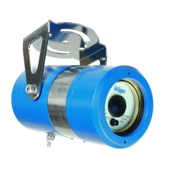
Dräger Flame 5000
Colour CCTV Flame Detector
Technical Manual
Technical Manual
en
2 - 34
WARNING
!
You must read, understand, and follow these instructions for use
before you use the flame detector in order to ensure the proper
Operation and function of the flame detector.
Advertisement
Table of Contents

Subscribe to Our Youtube Channel
Related Manuals for Dräger Flame 5000


Summary of Contents for Dräger Flame 5000
- Page 1 Dräger Flame 5000 Colour CCTV Flame Detector Technical Manual Technical Manual 2 - 34 WARNING You must read, understand, and follow these instructions for use before you use the flame detector in order to ensure the proper operation and function of the flame detector.
-
Page 2: Table Of Contents
Contents For Your Safety ........................3 Intended Use ........................6 Operation .......................... 20 Maintenance ........................21 Fault Finding ........................23 Technical Specifi cations ....................24 Approvals ........................... 26 Accessories ........................27 Supplier’s Declaration of Conformity ................28 Approval Certifi cates ......................29... -
Page 3: For Your Safety
For Your Safety For Your Safety Strictly follow the Instructions for Use Any use of the device requires full understanding and strict observation of these instructions. The device is only to be used for the purposes specifi ed herein. This manual should be carefully read by any individuals who have or will have responsibility for using or maintaining this product. - Page 4 For Your Safety Attention Information on power consumption and operating voltage of the detector can be found in the specifi cations section of this manual. This should be read and taken into consideration when specifying cable core sizes to be used. In addition, local regulations should be considered before wiring the system and installation should be completed by appopriately trained personnel.
- Page 5 For Your Safety Safety Symbols used in this Manual While reading this Manual, you will come across a number of warnings concerning some of the risks and dangers you may face while using the device. These warnings contain “signal” words that will alert you to the degree of hazard you may encounter.
-
Page 6: Intended Use
Intended Use Intended Use Dräger Flame Detector 5000 For use in an area which may contain potentially explosive atmostphere. Used to monitor and trigger the necessary control actions upon the detection of fi re or fl ame in a given environment Understanding the System Principle of Operation The Dräger Flame Detector 5000 can operate ‘stand alone’... - Page 7 Intended Use WARNING Do not open the enclosure in the presence of an explosive atmostphere. WARNING All permits and proper site procedure and practises must be followed and the equipment must be isolated from the power supply before opening the enclosure in the field. Field of View The sensor can detect fi...
- Page 8 Installation of the Dräger Flame Detector 5000 Installation of the Dräger Flame Detector 5000 In considering the application of the Dräger Flame Detector 5000 it is important to know of any conditions that may prevent the detector from responding. The detector provides reliable response to visible fl ames within its fi eld of view, and insensitivity to common false alarm sources.
- Page 9 Installation of the Dräger Flame Detector 5000 Detector Enclosure with Bracket Sighting requirements Observe the following: • Ensure the mounting position is free from vibration or movement • Prevent accidental knocking or forcing out of alignment • Where snow or ice build-up is likely, the heater should be enabled •...
- Page 10 Installation of the Dräger Flame Detector 5000 Exposure to Flare Radiation Flame detectors are frequently used where hydrocarbon fi re hazards are expected; these are quite often processing plants where a fl are stack is in use nearby. The detector should not have a direct view of the fl are. Flexibility of mounting location The detector requires a clear unobstructed view of the potential hazard.
- Page 11 Installation of the Dräger Flame Detector 5000 Detector mounting bracket Detector mounting bracket dimensions Dimensions shown in Millimeters...
- Page 12 Installation of the Dräger Flame Detector 5000 Electrical Install Detector Electronics Subassembly The fi eld wiring is accessed by removing the rear enclosure cover and all terminations are accessible without the need to access the electronics module mounted in the front portion of the enclosure. WARNING For European (ATEX) installations, IEC/EN60079-14 ‘Electrical Installations in Hazardous Areas’...
- Page 13 Installation of the Dräger Flame Detector 5000 then care should be taken to ensure the cable armour braid provides a suitable earth or that the enclosure earth stud (external) is separately connected to a suitable earth point using a single core 4mm earth cable.
- Page 14 Installation of the Dräger Flame Detector 5000 Detector Wiring Terminals (Rear Detector with cover removed) Relay Mode Connections The following table provides a function summary of each terminal if the detector is ordered in relay mode. Terminal Terminal No. Description +24v +24V Supply A 0V Supply A...
- Page 15 Installation of the Dräger Flame Detector 5000 4–20mA Connections The following table provides a function summary of each terminal if the detector is ordered in 4-20mA mode. Terminal Terminal No. Description +24v +24V Supply A 0V Supply A Tie to +24 Volts at panel 4-20 mA source VID+ Video +Ve...
- Page 16 RS485 to RS232 to terminals 7 & 14. Connect the RS232 input of a RS485 to RS232 to a PC install DFG software on the PC. The DFG Software can be used to interogate the Flame 5000 Detector, for any further assistance contact Dräger Safety UK Ltd.
- Page 17 Installation of the Dräger Flame Detector 5000 It is not necessary for the DC power cable to be a twisted pair or individually screened, a 2-core stranded cable with an overall screen is suffi cient. The minimum conductor size is determined by the cable length, the number of Flame Detectors on each loop, and the maximum allowed voltage drop at the last detector.
- Page 18 Installation of the Dräger Flame Detector 5000 Equation 2: Characteristic Impedence Calculation = Cable Impedance (mH) = Cable Capacitance ( F) = Characteristic Impedance (Ohms) The RS485 communications cabling should be a twisted pair stranded cable with an overall screen. Where multi- core cables are used then individual screened twisted pairs are recommended.
- Page 19 Installation of the Dräger Flame Detector 5000 body should then be fi tted to the mounting bracket. The bolts fi t into key slots in the bracket. Twist the enclosure to locate the bolts; these are then tightened using a 6mm Allen key. Electrical Installation In order to maintain compliance with the EMC regulations it is essential the electrical installation be engineered correctly.
-
Page 20: Operation
Operation Operation Detector Start-up procedure When the power is initially turned on there is a delay of approximately thirty seconds. The system performs an internal test and system initialisation. Detector Signals The Flame detector generates a 0-20mA signal to indicate its status, or provides relay outputs. This should be checked during the installation of the detector. -
Page 21: Maintenance
Maintenance Maintenance Detector Maintenance WARNING Repair of all equipment should be only performed in a safe area and by trained personnel. Once installed there are no user serviceable parts within the detector. The only servicing requirements are to ensure that the detector is fully functional and to ensure that the lenses are clean. The terminal compartment cover and front cover threads must be lightly lubricated with non-setting grease prior to re-assembly. - Page 22 Fault Finding • Check the ‘O’ ring seal on the enclosure cover to ensure that it is not damaged or perished; replace as required. NOTE: That the ingress protection is compromised if the seal is not correct. • Clean the enclosure faceplate (inside) with a mild detergent solution and a soft cloth until the window is clear of all contamination.
-
Page 23: Fault Finding
Fault Finding Fault Finding Removal of the Electronics There are no user replaceable parts within the electronic module, any attempt to repair or dismantle the electronic sub- assemblies will void the warranty. If any fault is suspected within the electronics module the module is to be returned to Dräger Safety UK Ltd for investigation and repair if required. -
Page 24: Technical Specifi Cations
Technical Specifi cations Technical Specifi cations Mechanical Enclosure Enclosure Material: Aluminium Alloy Grade LM25, Stainless Steel 316 Enclosure Finish: Epoxy Coated Finish, Dräger Blue Weight: 2.5 kg, 5.5 lbs (2.8 kg, 6.2 lbs Stainless Steel ver) Dimensions (L x D): 220 x 100 mm, (9”... - Page 25 Approvals Electrical Operating Voltage: 18-32VDC (24VDC Nominal) inc ripple, (Max 30VDC in Canada) Supply Ripple: 1V pk-pk Power Consumption: 6W (max. 15W with Heater) Heater Power Consumption: Detector Shutdown Voltage: <17VDC (low supply) Power-On Delay: No more than 30 seconds, during in which System Testing and System Initialisation occurs.
-
Page 26: Approvals
SEAL CONDUIT WITHIN 18" OF ENCLOSURE ENTRANCE ¾" NPT Dual Maximum Current: 700mA Aberdeen, Scotland, AB12 4RR WARNING: DO NOT OPEN WHEN EXPLOSIVE ATMOSPHERE MAY BE PRESENT WARNING: REFER TO FLAME 5000 TECHNICAL MANUAL BEFORE INSTALLING OR MAINTAINING THIS UNIT... -
Page 27: Accessories
420 93 20 Dräger Flame 5000, M20, Relay, NTSC video mode, Stainless Steel 420 93 21 Dräger Flame 5000, 3/4 NPT, Relay, NTSC video mode, Stainless Steel 420 93 22 Dräger Flame 5000, 3/4 NPT, 4-20mA, PAL video mode, Stainless Steel 420 93 23 Dräger Flame 5000, M25, 4-20mA, PAL video mode, Stainless Steel... -
Page 28: Supplier's Declaration Of Conformity
Supplier’s Declaration of Conformity... -
Page 29: Approval Certifi Cates
Approval Certifi cates... - Page 35 Draeger Safety UK Ltd Ullswater Close Blyth Riverside Business Park Blyth, Northumberland NE24 4RG, United Kingdom Tel: +44 (0)1670 352 891 Fax: +44 (0)1670 540 033 www.draeger.com Distributed in the US by: Draeger Safety, Inc 101 Technology Drive Pittsburgh, PA 15275 Tel: +1 412 787 83 83 Fax: +1 412 787 22 07 Telex: 0230866704...
Need help?
Do you have a question about the Flame 5000 and is the answer not in the manual?
Questions and answers