
Related Manuals for Dräger FD 10 Series


Summary of Contents for Dräger FD 10 Series
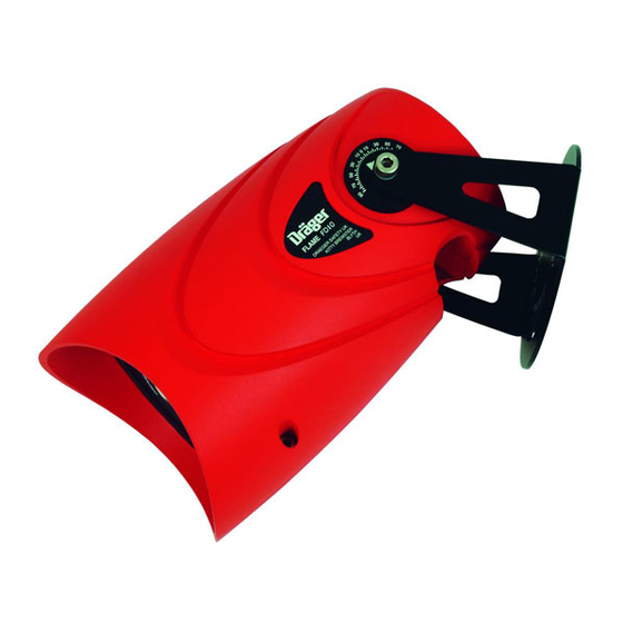
- Page 1 Draeger Flame Detector FD 10 Range Instructions For Use WARNING You must read, understand, and follow these instructions for use before you use the flame detector in order to ensure the proper operation and function of the flame detector.
-
Page 2: Safety Symbols Used In This Manual
Safety Symbols used in this Manual For Your Safety Safety Symbols used in this Manual While reading this Manual, you will come across a number of warnings concerning Strictly follow these Instructions for Use some of the risks and dangers you may face while using the device. These warnings Any use of the fl... -
Page 3: Intended Use
Intended Use Intended Use heavy rain and dense fog. - The angle at which the sensor is positioned, this should always be downward and at a minimum of 10° - 20°. The Draeger Flame Detector FD10 range is intended to monitor and trigger the The device does not contain any parts that can be serviced by the user. -
Page 4: Electrical Installation
Installing Electrical Installation NOTICE When installing, the entire wiring must meet currently valid national regulations regarding the installation of electrical devices, and - if necessary Where terminals 35 & 37 are not interfaced with vendor panels but - the national regulations regarding the installation in potentially explosive the alarm relay is required it is necessary to place a hard wired link atmospheres. -
Page 5: Mechanical Installation
Operation Figure 3: Wiring operation as 3-wire device with 4-20mA output Note: When this equipment is installed within either: NEC 500 Class 1 Div 1 NEC 505 Class 1 Zone 1 Certifi ed areas then it must be installed using type MC-HL cable (Metal Clad for Hazardous Locations) Mechanical Installation 12 13... -
Page 6: Operation
Operation Operation Maintenance When the power is initially turned on there is a delay of approximately thirty seconds Observe respective national regulations. (e.g. in Europe 60079-17 applies.) where the system performs an internal test and system initialisation. The Draeger Flame Detector FD10 Range performs an automatic optics test every An optical and hardware check is performed within the testing. - Page 7 Accessories Accessories 1300 IR Flame Detector 1700 UV Flame Detector 2300 UVIR Flame Detector 0mA = Fault 0mA = Fault 0mA = Fault The following accessories and spare parts are off ered for the Draeger Flame FD10 Range 1.9mA ± 0.15mA = Optical Fault 1.9mA ±...
-
Page 8: Technical Data
Technical Data Technical Data Ambient conditions -40° to +60°C (-40 to +140°F), 91.5 to 105.5kPA, 0-99% rel.hum IP Rating IP 67, NEMA 4X (with O-rings fi tted) Supply voltage Flame 1300 18 to 32VDC, current consumption 160mA quiescent state at 24 VDC ( maximum 230mA) Flame 1700 18 to 32VDC, current consumption 160mA quiescent state at 24 VDC ( maximum 180mA) Flame 2300... - Page 9 Draeger Safety UK Ltd Distributed in the US by: Ullswater Close Draeger Safety, Inc Blyth Riverside Business Park 101 Technology Drive Blyth, Northumberland Pittsburgh, PA 15275 NE24 4RG United Kingdom Tel: +1 412 787 83 83 Tel: +44 1670 352 891 Fax: +1 412 787 22 07 Fax: +44 1670 450 033 Telex: 0230866704...
Need help?
Do you have a question about the FD 10 Series and is the answer not in the manual?
Questions and answers