
Related Manuals for Dräger Messkopf Polytron SE Ex PR M1 DQ


Summary of Contents for Dräger Messkopf Polytron SE Ex PR M1 DQ
- Page 1 Polytron SE Ex PR M1/2 DQ Polytron SE Ex LC M1/2 DD Remote Sensor DQ NPT Alu/Steel Polytron SE Ex HT M DQ Instructions for use de · en · fr · es...
- Page 2 Gebrauchsanweisung .............3 Instructions for use ...............27 Notice d'utilisation ..............51 Instrucciones de uso.............75...
-
Page 3: Table Of Contents
Inhaltsverzeichnis Inhaltsverzeichnis Sicherheitsbezogene Informationen........5.2.2 Remote Sensor DQ NPT Alu/Steel ..........5.2.3 Messkopf Polytron SE Ex HT M DQ .......... Informationen zu Sicherheitshinweisen und Warnhinweisen ..5.2.4 Wiedereinschalten nach Sensorwechsel ........1.1.1 Sicherheitshinweise..............Verwendung einer Sensormembran oder des Staubschutzfilters 1.1.2 Warnhinweise................ -
Page 4: Sicherheitsbezogene Informationen
Sicherheitsbezogene Informationen Sicherheitsbezogene Informationen – Gebrauchsanweisung nicht entsorgen. Aufbewahrung und ordnungsgemäße Verwendung durch die Nutzer sicherstellen. Diese Gebrauchsanweisung kann in weiteren Sprachen in der Datenbank für – Nur geschultes und fachkundiges Personal darf dieses Produkt verwenden. Technische Dokumentation (www.draeger.com/ifu) in elektronischer Form –... -
Page 5: Beschreibung
Beschreibung Beschreibung Warnzeichen Signalwort Folgen bei Nichtbeachtung Produktübersicht WARNUNG Hinweis auf eine potenzielle Gefahrensi- tuation. Wenn diese nicht vermieden wird, können Tod oder schwere Verlet- zungen eintreten. VORSICHT Hinweis auf eine potenzielle Gefahrensi- tuation. Wenn diese nicht vermieden wird, können Verletzungen eintreten. Kann auch als Warnung vor unsachge- mäßem Gebrauch verwendet werden. -
Page 6: Verwendungszweck
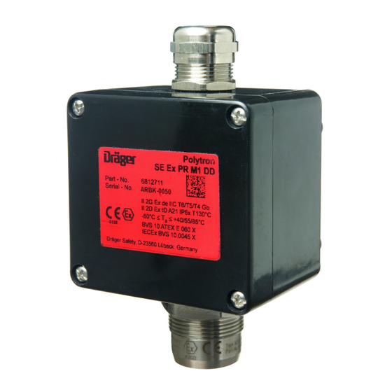
Montage und Inbetriebnahme Einschränkungen des Verwendungszwecks Bezeichnung Gehäusetyp DrägerSen- Messbereich Die Messköpfe sind nicht für den Einsatz bei erhöhtem Sauerstoffgehalt (> 21 Vol.-% O ) zugelassen. Keiner der in diesem Dokument aufgeführten Polytron SE Ex PR M1 PR M DQ 0 - 100 %UEG Messköpfe und Sensoren ist für den Betrieb in sauerstoffangereicherten Atmosphären zertifiziert und zugelassen. -
Page 7: Elektrische Installation
Montage und Inbetriebnahme – Wird der Messkopf zur Detektion von brennbaren Dämpfen verwendet, so – Die Kabelverschraubung ist ausschließlich für die ortsfeste Installation muss der Bodenabstand so gering wie möglich gewählt, aber auf zugelassen. Sie ist geeignet für Leitungsdurchmesser von 7 bis 12 mm. Das Zugänglichkeit bei Kalibrierarbeiten geachtet werden. -
Page 8: Verbindung Zwischen Messkopf Polytron Se Ex Ht Mdq Und Baugruppenträger Oder Transmittern
Montage und Inbetriebnahme muss die Materialverträglichkeit hinsichtlich Chemikalien oder aggressiven Substanzen geprüft werden. Weiterhin ist auf einwandfreien Sitz des O-Rings (1) zu achten. 4.2.2 Verbindung zwischen Messkopf Polytron SE Ex HT M DQ und Baugruppenträger oder Transmittern – Mit 3-adriger, abgeschirmter Leitung, Abschirmgeflecht mit Bedeckungsgrad ≥80 %. -
Page 9: Anschluss An Transmitter
Montage und Inbetriebnahme 4.2.3 Anschluss an Transmitter Sicherheitsrelevante Hinweise zum Messkopfgehäuse HT (Hochtemperatur, Typ Range 2000) 4.2.3.1 Polytron 5200/8200 Folgende Angaben zum Messkopfgehäuse berücksichtigen: – Installation 3 - core field wiring 5 - core field wiring Das Gehäuse ist mit den beiden äußeren Laschen zu montieren. Das (Sensors: DD, DQ, LC) (Sensors: DD, DQ, LC) Gehäuse darf unter keinen Umständen durch eine Kabeleinführung gestützt... - Page 10 Montage und Inbetriebnahme Daraus ergeben sich für die verschiedenen Aderquerschnitte folgende 4.2.3.2 PointGard 3200 maximale Entfernungen: Adernquerschnitt 1,0 mm 1,5 mm 2,5 mm max. Leitungslänge 30 m 50 m 75 m Bei Verwendung eines 3-adrigen Kabels: Um den Anschluss von 3-adrigen Kabeln zu erleichtern, steht der Ersatzteilsatz (Bestellnr.
- Page 11 Montage und Inbetriebnahme Daraus ergeben sich für die verschiedenen Aderquerschnitte folgende Bei Verwendung eines 3-adrigen Kabels: maximale Entfernungen: ● Klemmen gemäß Abbildung A1 anschließen. ● Die vormontierten Kabelteile mit der entsprechenden Feldverkabelung Adernquerschnitt 1,0 mm 1,5 mm 2,5 mm in einer Zwillingsaderendhülse zusammenführen und crimpen. max.
- Page 12 Montage und Inbetriebnahme 4.2.3.3 PEX 1000 Daraus ergeben sich für die verschiedenen Aderquerschnitte folgende maximale Entfernungen: Messkopf Aderquerschnitt Sensorstrom 0,5 mm 0,75 mm 1,0 mm 1,5 mm (36 Ohm/km) (24 Ohm/km) (18 Ohm/km) Ohm/km) Polytron SE Ex PR ... DQ, Remote Sensor 170 m 260 m...
- Page 13 Montage und Inbetriebnahme 4.2.3.4 PEX 3000 – Der Leitungswiderstand je Ader darf 10 Ohm nicht überschreiten. – Für die Verdrahtung zwischen Gasmesstransmitter und Messkopf (z. B. Messkopf SE Ex ... DQ) nur Leitungen mit einem Querschnitt von mindestens 0,75 mm verwenden.
-
Page 14: Messkopf In Betrieb Nehmen
Montage und Inbetriebnahme Messkopf in Betrieb nehmen – Obwohl die Messköpfe vor der Auslieferung auf Funktion geprüft werden, muss nach deren Installation eine Inbetriebnahme einschließlich der Kalibrierung von Nullpunkt und Empfindlichkeit durchgeführt werden. Die VORSICHT Inbetriebnahme muss mit einer Funktionsprüfung der kompletten Verzögerte Ansprechzeit an der Auswerteeinheit. -
Page 15: Sensorstrom Einstellen
Wartung 4.3.2 Sensorstrom einstellen – Signalübertragung zur Auswerteeinheit und Alarmgabe überprüfen - siehe Gebrauchsanweisung der verwendeten Auswerteeinheit. Die Sensoren DrägerSensor PR M DQ, PR NPT DQ und HT M DQ werden mit – Messkopf kalibrieren / justieren. Weitere Informationen im folgenden 255 mA betrieben. -
Page 16: Messköpfe Polytron Se Ex Pr M1/2 Dq Und Se Ex Lc M1/2 Dq
Wartung 5.2.1 Messköpfe Polytron SE Ex PR M1/2 DQ und SE Ex LC 7. Klemmenkasten schließen, dabei auf Staubfreiheit achten M1/2 DQ 5.2.2 Remote Sensor DQ NPT Alu/Steel 1 2 3 1 2 3 1. Nach Abschalten der Betriebsspannung Klemmenkasten des Messkopfes öffnen und Oberteil abnehmen. -
Page 17: Messkopf Polytron Se Ex Ht M Dq
Wartung 5.2.3 Messkopf Polytron SE Ex HT M DQ 7. Oberteil mit zugehörigem Silikon-Dichtring aufsetzen und mit den vier Schrauben festziehen (Drehmoment 3,5 Nm), dabei auf Staubfreiheit achten. 5.2.4 Wiedereinschalten nach Sensorwechsel 1. Auswerteeinheit oder Transmitter wieder einschalten bzw. Kanaleinschub wieder in den Baugruppenträger einschieben. -
Page 18: 6 Entsorgung
Entsorgung Sensormembran und Staubschutzfilter dürfen nicht miteinander kombiniert Baujahr durch Seriennummer werden. Messköpfe Polytron SE Ex LC M1/2 Entsorgung Betriebsparameter Dieses Produkt darf nicht als Siedlungsabfall entsorgt werden. Es ist daher mit dem nebenstehenden Symbol gekennzeichnet. Konstantstrom, Sensor 276 mA Dräger nimmt dieses Produkt kostenlos zurück. -
Page 19: Eac
Technische Daten bei Lagerung -40 bis +65 °C II 2G Ex eb IIC T3 Gb (gilt auch für Ersatzsensoren): 700 bis 1300 mbar II 2D Ex tb IIIC T200°C Db 10 bis 90 % rel. Feuchte, nicht-kondensierend Lagerzeit unbegrenzt IP 66 Max. power 9 Watts Das Baujahr ergibt sich aus dem 3. -
Page 20: Abmessungen
Remote Sensor DQ NPT Alu/Steel 150 x 175 x 130 inkl. Sensor Polytron SE Ex HT M DQ 150 x 152 x 85 inkl. Sensor und Kabelverschraubung Abmessungen und Bohrmaße (in mm) Messkopf Polytron SE Ex PR M1 DQ Gebrauchsanweisung... - Page 21 Technische Daten Messkopf Polytron SE Ex PR M2 DQ Remote Sensor DQ NPT Alu/Steel Messkopf Polytron SE Ex LC M2 DD (Durchmesser der Wandbefestigungslöcher 7 mm) 82,60 60,71 Gebrauchsanweisung...
-
Page 22: Bestellliste
Messkopf Polytron SE Ex HT M DQ Benennung und Beschreibung Bestellnr. (Durchmesser der Wandbefestigungslöcher 6 mm) Messkopf Polytron SE Ex PR M1 DQ 68 12 711 Messkopf Polytron SE Ex PR M2 DQ 68 12 710 Remote Sensor DQ NPT Alu... - Page 23 Technische Daten Benennung und Beschreibung Bestellnr. Fernkalibrieradapter LC 68 12 482 Ersatzteile DrägerSensor PR M DQ 68 14 140 DrägerSensor PR NPT DQ 68 14 150 DrägerSensor PR NPT DQ S 37 01 800 DrägerSensor LC M 68 10 350 DrägerSensor LC NPT 68 10 675 DrägerSensor HT M DQ...
-
Page 24: 8 Konformitätserklärung
Konformitätserklärung Konformitätserklärung Gebrauchsanweisung... - Page 25 Konformitätserklärung Gebrauchsanweisung...
- Page 26 Konformitätserklärung Gebrauchsanweisung...
- Page 27 Contents Contents Safety-related information ............5.2.3 Polytron SE Ex HT M DQ sensing head ........5.2.4 Switching back on after replacing the sensor ......Information on safety notes and warnings........Using a sensor diaphragm or the anti-dust filter ......1.1.1 Safety notes ................
-
Page 28: Safety-Related Information
Safety-related information Safety-related information – Only specialist, trained personnel are permitted to check, repair and maintain the product as described in the instructions for use. Any maintenance work that is not described in the instructions for use is These instructions for use may be downloaded in other languages from the only permitted to be carried out by Dräger or personnel trained by Dräger. -
Page 29: Description
Description Description Alert icon Signal word Consequences in case of nonob- servance Product overview NOTICE Indicates a potentially hazardous situa- tion. If not avoided, it could result in damage to the product or environment. Polytron Polytron SE Ex PR M1 DQ SE Ex PR M2 DQ Remote Sensor Polytron... -
Page 30: Intended Use
Installation and commissioning Limitations on the intended use Name Housing DrägerSen- Measuring type range The sensing heads are not approved for use in environments with an increased oxygen content (>21 Vol% O ). None of the sensing heads and sensors given in Polytron SE Ex PR M1 PR M DQ 0–100 %LEL... -
Page 31: Electrical Installation
Installation and commissioning Mounting the sensing heads – Place the cable shielding around the plastic cone on the cable gland as shown in the figure, and insert into the metal cable gland. Tightening the Polytron SE Ex PR M1/M2 DQ 4 screws (4 mm diameter), through cable gland means that the shielding is in electrical contact with the Polytron SE Ex LC M1/M2 DD... -
Page 32: Connection Between Polytron Se Ex Ht M Dq Sensing Head And Rack Or Transmitters
Installation and commissioning 4.2.2 Connection between Polytron SE Ex HT M DQ sensing head and rack or transmitters Installing the sheathed line – With 3-wire, shielded line, shield braiding with ≥80% coverage. Max. outer The 3-wire shielded sheathed line is disconnected or stripped in accordance diameter: 12 mm. -
Page 33: Connection To Transmitter
Installation and commissioning 4.2.3 Connection to transmitter – Installation The housing should be installed using the two outer flaps. The housing is 4.2.3.1 Polytron 5200/8200 not permitted to be supported by a cable entry under any circumstances. The silicone seal should be fitted between the housing and the cover. It is 3 - core field wiring 5 - core field wiring important that the cover is fitted securely to the housing body. - Page 34 Installation and commissioning This results in the following maximum distances for the different wire cross- 4.2.3.2 PointGard 3200 sections: Wire cross-section 1.0 mm 1.5 mm 2.5 mm Max. line length 30 m 50 m 75 m When using a 3-wire cable: To allow 3-wire cables to be connected with greater ease, the spare part set (ordering no.
- Page 35 Installation and commissioning This results in the following maximum distances for the different wire cross- When using a 3-wire cable: sections: ● Connect terminals in accordance with figure A1. ● Join the preassembled cable parts with the corresponding field cabling Wire cross-section 1.0 mm 1.5 mm...
- Page 36 Installation and commissioning 4.2.3.3 PEX 1000 This results in the following maximum distances for the different wire cross- sections: Sensing head Wire cross-section Sensor current 0.5 mm 0.75 mm 1.0 mm 1.5 mm ohms/km) ohms/km) ohms/km) ohms/km) Polytron SE Ex PR ...
- Page 37 Installation and commissioning 4.2.3.4 PEX 3000 – The line resistance per wire must not exceed 10 ohms. – For the wiring between the gas measurement transmitter and sensing head (e.g. sensing head SE Ex ... DQ), only use wires with a cross-section of at least 0.75 mm .
-
Page 38: Commissioning The Sensing Head
Installation and commissioning Commissioning the sensing head – Although the sensing heads have been factory-tested before delivery, the commissioning process following installation must include zero-point and sensitivity testing. The commissioning process must be concluded with a CAUTION functional test of the complete gas detection system. Delayed response time on the control unit. -
Page 39: Calibrating/Adjusting The Polytron Se Ex Sensing Head
Maintenance The warm-up time can be found in the instructions for use for the sensors. Every six months: – Inspection by specialists. 4.3.3 Calibrating/adjusting the Polytron SE Ex sensing The length of the inspection intervals must be established in each individual head case depending on safety considerations, process conditions, and the technical requirements of the equipment. -
Page 40: Polytron Se Ex Pr M1/2 Dq And Se Ex Lc M1/2 Dq Sensing Heads
Maintenance 5.2.1 Polytron SE Ex PR M1/2 DQ and SE Ex LC M1/2 DQ 7. Close the terminal box, ensuring that it is free of dust sensing heads 5.2.2 Remote Sensor DQ NPT Alu/Steel 1 2 3 1 2 3 1. - Page 41 Maintenance 5.2.3 Polytron SE Ex HT M DQ sensing head 7. Position the upper part with corresponding silicone sealing ring and secure using the four screws (torque 3.5 Nm), ensuring that the device is free of dust. 5.2.4 Switching back on after replacing the sensor 1.
- Page 42 Disposal Disposal Polytron SE Ex LC M1/2 DD sensing heads This product must not be disposed of as household waste. This is indi- Operating parameters cated by the adjacent symbol. You can return this product to Dräger free of charge. For information Constant current, sensor 276 mA please contact the national marketing organizations or Dräger.
- Page 43 Technical data During storage -40 to +65 °C 2. Housing: Flameproof Electrical Enclosures Ltd., Oldbury, (also applies to replacement sensors): 700 to 1300 mbar England 10 to 90% relative humidity, non-condensing Range 2000 type Unlimited storage time II 2G Ex eb IIC T3 Gb The year of manufacture is the 3rd letter of the serial number located on the name plate: R = 2022, S = 2023, T = 2024 and so on For instance: Serial number ARSH-0054, the 3rd letter is S, II 2D Ex tb IIIC T200 °C Db...
- Page 44 Technical data Polytron SE Ex LC M1 DD sensing head – Срок службы: 10 лет – Максимальный срок хранения: 5 года (срок хранения может быть увеличен при сервисном обслуживании) Условия транспортировки и хранения: -40 до +65 °Cот 700 до 1300 гПаот 10 до 90 % относительной влажности, без...
- Page 45 Technical data Polytron SE Ex PR M2 DQ sensing head Remote Sensor DQ NPT Alu/Steel Polytron SE Ex LC M2 DD sensing head (Diameter of holes for wall mounting: 7 mm) 82,60 60,71 Instructions for use...
- Page 46 Technical data Polytron SE Ex HT M DQ sensing head Designation and description Order no. (Diameter of holes for wall mounting: 6 mm) Polytron SE Ex PR M1 DQ sensing head 68 12 711 Polytron SE Ex PR M2 DQ sensing head 68 12 710 Remote Sensor DQ NPT Alu 37 06 933...
- Page 47 Technical data Designation and description Order no. Remote calibration adapter LC 68 12 482 Spare parts DrägerSensor PR M DQ 68 14 140 DrägerSensor PR NPT DQ 68 14 150 DrägerSensor PR NPT DQ S 37 01 800 DrägerSensor LC M 68 10 350 DrägerSensor LC NPT 68 10 675...
- Page 48 Declaration of Conformity Declaration of Conformity Instructions for use...
- Page 49 Declaration of Conformity Instructions for use...
- Page 50 Declaration of Conformity Instructions for use...
- Page 51 Sommaire Sommaire Informations relatives à la sécurité........5.2.1 Têtes de mesure Polytron SE Ex PR M1/2 DQ et SE Ex LC M1/2 DQ ..................... Informations relatives aux avertissements et consignes de 5.2.2 Remote Sensor DQ NPT Alu/Steel ..........sécurité..................5.2.3 Tête de mesure Polytron SE Ex HT M DQ ........
- Page 52 Informations relatives à la sécurité Informations relatives à la sécurité – Ne pas jeter la notice d'utilisation. Veillez à ce que les utilisateurs conservent et utilisent cette notice de manière adéquate. Cette notice d’utilisation peut être téléchargée dans d’autres langues sous –...
- Page 53 Description Description Symboles Mention Conséquences en cas de non-respect d'avertisse- Présentation du produit ment AVERTISSEMENT Signale une situation potentiellement dangereuse qui, si elle n'est pas évitée, peut constituer un danger de mort ou d'accident grave. ATTENTION Signale une situation potentiellement dangereuse qui, si elle n'est pas évitée, peut entraîner des blessures.
- Page 54 Montage et mise en service Restrictions posées au domaine Description Type de boî- DrägerSen- Plage de mesure d'application tier Polytron SE Ex PR M1 PR M DQ 0 - 100 %LIE Les têtes de mesure ne peuvent être utilisées en présence d'un taux d'oxygène élevé...
- Page 55 Montage et mise en service 4.2.1 Connexion entre les têtes de mesure Polytron SE Ex – Si la tête de mesure est utilisée pour la détection de vapeurs inflammables, on fera en sorte que la distance au sol soit aussi réduite que possible tout PR M1/2 DQ ou SE Ex LC M1/2 DD et le rack en veillant au libre accès pour les tâches de calibrage.
- Page 56 Montage et mise en service l'installation, il faut contrôler la compatibilité du matériau avec les substances chimiques ou des substances agressives. De plus, contrôler si le joint torique (1) est parfaitement monté. 4.2.2 Connexion entre la tête de lecture Polytron SE Ex HT M DQ et le rack modulaire ou les transmetteurs –...
- Page 57 Montage et mise en service 4.2.3 Raccordement au transmetteur Notes de sécurité portant sur le boîtier du capteur HT (haute température, type Range 2000) 4.2.3.1 Polytron 5200/8200 Prendre en compte les indications suivantes relatives au boîtier de la tête de mesure : 3 - core field wiring 5 - core field wiring...
- Page 58 Montage et mise en service Il en résulte les distances maximales suivantes en fonction des différentes 4.2.3.2 PointGard 3200 sections de fil<:hs>: Section du conducteur 1,0 mm 1,5 mm 2,5 mm Longueur maximale du 30 m 50 m 75 m câble En cas d’utilisation d’un câble à...
- Page 59 Montage et mise en service Il en résulte les distances maximales suivantes en fonction des différentes 4. Retirer l’isolation sur 5 à 7 mm. sections de fil<:hs>: 5. Mettre les embouts de fils sur la tresse du câble. En cas d’utilisation d’un câble à 3 fils : Section du conducteur 1,0 mm 1,5 mm...
- Page 60 Montage et mise en service 4.2.3.3 PEX 1000 Il en résulte les distances maximales suivantes en fonction des différentes sections de fil<:hs>: Tête de mesure Section de fil Courant du 0,5 mm 0,75 mm 1,0 mm 1,5 mm capteur (36 ohm/km) (24 ohm/km) (18 ohm/km) (12 ohm/k Polytron SE Ex PR…...
- Page 61 Montage et mise en service 4.2.3.4 PEX 3000 – La résistivité ne doit pas dépasser 10 ohms par conducteur. – Pour le câblage entre le transmetteur de gaz et la tête de mesure (par ex. tête de mesure SE Ex ... DQ), utiliser uniquement des câbles présentant une section d'au moins 0,75 mm .
- Page 62 Montage et mise en service Réaliser avec soin toutes les liaisons du câble de mesure. Les câbles de – Tenir compte de la densité du gaz ! Dans le cas de gaz dont la densité est mesure doivent être choisis conformément aux directives d’installation en inférieure à...
- Page 63 Maintenance À intervalles réguliers, AVERTISSEMENT à définir par les responsables de l'équipement de détection de fuites de gaz, et Pour un verrouillage d'alarme, aucun signal électrique n'est généré qui renvoie en tout état de cause à intervalles ne dépassant pas 6<:hs>mois<:hs>: au verrouillage d'alarme.
-
Page 64: Remote Sensor Dq Npt Alu/Steel
Maintenance 5.2.1 Têtes de mesure Polytron SE Ex PR M1/2 DQ et SE Borne 3 câble noir Ex LC M1/2 DQ 7. Fermer la centrale en veillant à l'absence de poussière 5.2.2 Remote Sensor DQ NPT Alu/Steel 1 2 3 1 2 3 1. - Page 65 Maintenance 5.2.3 Tête de mesure Polytron SE Ex HT M DQ 7. Monter la partie supérieure avec le joint d'étanchéité en silicone et la bloquer avec les quatre vis (couple de serrage 3,5 Nm), en veillant également à l'absence de poussière. 5.2.4 Remise en service après remplacement du capteur 1.
- Page 66 Élimination Élimination Année de fabrication indiquée par le numéro de série Il est interdit d'éliminer ce produit avec les déchets domestiques. C'est pourquoi, il est marqué du symbole ci-contre. Dräger reprend gratuitement ce produit. Pour de plus amples informa- Têtes de mesure Polytron SE Ex LC tions, veuillez contacter les distributeurs nationaux ou vous adresser M1/2 DD directement à...
- Page 67 Caractéristiques techniques En mode mesure : 1er DrägerSensor HT M DQ : Dräger Safety • -23560 Lübeck • Allemagne Polytron SE Ex PR M1/2 DQ -50 jusqu’à +40/55/85 °C DrägerSensor HT M DQ Polytron SE Ex PR NPT1 DQ -40 jusqu'à +40/55/60 °C -40 jusqu'à...
-
Page 68: Eac
Caractéristiques techniques Tête de mesure Dimensions (l x En mode mesure : -50 jusqu’à +40/55/85/150 °C h x P) Température de la superficie : +130 °C / +195 °C 800 jusqu’à 1200 mbar, Polytron SE Ex LC M2 DD 136 x 124 x 56 De 5 à... - Page 69 Caractéristiques techniques Tête de mesure Polytron SE Ex LC M1 DD Tête de mesure Polytron SE Ex PR M2 DQ Tête de mesure Polytron SE Ex LC M2 DD Notice d'utilisation...
- Page 70 Caractéristiques techniques Remote Sensor DQ NPT Alu/Steel Tête de mesure Polytron SE Ex HT M DQ (Diamètre des alésages de la fixation murale 7 mm) (Diamètre des alésages de la fixation murale 6 mm) 82,60 60,71 ca.12 Liste de commande Désignation et description N°...
- Page 71 Caractéristiques techniques Désignation et description N° de com- Désignation et description N° de com- mande mande Tête de mesure Polytron SE Ex PR M1 DQ 68 12 711 Jeu de pièces détachées pour membranes 21,50 x 14,50, 83 26 840 2 unités Tête de mesure Polytron SE Ex PR M2 DQ 68 12 710...
- Page 72 Déclaration de conformité Déclaration de conformité Notice d'utilisation...
- Page 73 Déclaration de conformité Notice d'utilisation...
- Page 74 Déclaration de conformité Notice d'utilisation...
- Page 75 Índice de contenidos Índice de contenidos Información relativa a la seguridad ........5.2.3 Detector Polytron SE Ex HT M DQ ..........5.2.4 Reconexión tras el cambio del sensor ........Información sobre indicaciones de seguridad y avisos ....Utilización de la membrana del sensor o del filtro de protección 1.1.1 Indicaciones de seguridad............
- Page 76 Información relativa a la seguridad Información relativa a la seguridad – No eliminar las instrucciones de uso. Se debe garantizar que los usuarios guarden y usen las instrucciones correctamente. Estas instrucciones de uso se pueden descargar en diferentes idiomas en –...
- Page 77 Descripción Descripción Símbolo de Palabra de adver- Consecuencias del incumplimiento advertencia tencia Vista general del producto ADVERTENCIA Advertencia de una situación potencial- mente peligrosa. En caso de no evitarse, pueden producirse lesiones graves e incluso letales. ATENCIÓN Advertencia de una situación potencial- mente peligrosa.
- Page 78 Montaje y puesta en marcha Restricciones del uso previsto Designación Tipo de car- DrägerSen- Rango de medi- casa ción No está permitido el uso de los detectores con un contenido elevado de oxígeno (> 21 Vol.-% O ). Ninguno de los detectores mencionados en este Polytron SE Ex PR M1 PR M DQ 0–100 % L.I.E.
- Page 79 Montaje y puesta en marcha 4.2.1 Conexión entre los detectores Polytron SE Ex PR – Si el detector se utiliza para la detección de vapores inflamables, la distancia respecto al suelo debe mantenerse lo más reducida posible, a la M1/2 DQ o SE Ex LC M1/2 DD y los portamódulos o vez que se observa la accesibilidad para los trabajos de calibración.
- Page 80 Montaje y puesta en marcha instalación debe comprobarse la compatibilidad del material respecto a sustancias químicas o sustancias agresivas. También debe observarse el asiento correcto de la junta tórica (1). 4.2.2 Conexión entre el detector Polytron SE Ex HT M DQ y los portamódulos o transmisores –...
- Page 81 Montaje y puesta en marcha 4.2.3 Conexión al transmisor Indicaciones relevantes para la seguridad para la carcasa del detector HT (alta temperatura, tipo Range 2000) 4.2.3.1 Polytron 5200/8200 Observar los siguientes datos sobre la carcasa del detector: – Instalación 3 - core field wiring 5 - core field wiring La carcasa debe montarse con las dos lengüetas exteriores.
- Page 82 Montaje y puesta en marcha Por consiguiente, las distancias máximas para las distintas secciones de hilo 4.2.3.2 PointGard 3200 son las siguientes: Sección de hilo 1,0 mm 1,5 mm 2,5 mm Longitud máx. de cable 30 m 50 m 75 m Si se usa un cable de 3 hilos: Para facilitar la conexión de cables de 3 hilos, se dispone del juego de repuestos (Nº...
- Page 83 Montaje y puesta en marcha Por consiguiente, las distancias máximas para las distintas secciones de hilo Si se usa un cable de 3 hilos: son las siguientes: ● Conectar las bornas como se indica en la figura A1. ● Unir y enganchar las partes del cable premontadas con el cableado de Sección de hilo 1,0 mm 1,5 mm...
- Page 84 Montaje y puesta en marcha 4.2.3.3 PEX 1000 Por consiguiente, las distancias máximas para las distintas secciones de hilo son las siguientes: Detector Sección del cable Corriente del 0,5 mm 0,75 mm 1,0 mm 1,5 mm sensor (36 Ohm/km) (24 Ohm/km) (18 Ohm/km) Ohm/km) Polytron SE Ex PR ...
- Page 85 Montaje y puesta en marcha 4.2.3.4 PEX 3000 – La resistencia específica de cada hilo no debe sobrepasar los 10 ohmios. – Para el cableado entre el transmisor de medición de gas y el detector (por ejemplo, detector SE Ex ... DQ), utilizar solamente cables con una sección transversal mínima de 0,75 mm .
- Page 86 Montaje y puesta en marcha Realizar todas las conexiones del cable de medición con sumo cuidado. Los – ¡Observar la densidad del gas! En el caso de gases cuya densidad sea cables de medición deben seleccionarse según las normas de construcción inferior a la del aire, como el hidrógeno, metano o amoníaco, el detector para el rango de temperatura de funcionamiento previsto.
- Page 87 Mantenimiento Durante la puesta en marcha: ADVERTENCIA – Ajustar la corriente del sensor. Para más información, consulte el siguiente En caso de haberse realizado un bloqueo de alarmas, no se genera ninguna capítulo: "Ajustar la corriente del sensor", página 87. señal eléctrica que indique el bloqueo de alarmas.
- Page 88 Mantenimiento Cambiar el sensor 4. Desenroscar el sensor usado, acortar de forma correspondiente los cables del nuevo sensor y desaislarlos aprox. de 8 a 10 mm. Utilizar los protectores de cables suministrados. ADVERTENCIA El sensor solo debe cambiarse con la unidad de evaluación apagada o con el ADVERTENCIA transmisor apagado en zonas potencialmente explosivas.
- Page 89 Mantenimiento Para la instalación del Remote Sensor DQ NPT Alu/Steel, véanse las Abrazadera 3 cable negro instrucciones de montaje Junction Box Ex d (Nº ref. 4544286). Abrazadera 4 (en caso de estar disponible) no está 5.2.3 Detector Polytron SE Ex HT M DQ conectada.
- Page 90 Eliminación de cadena larga, como el n-nonano). La influencia sobre la sensibilidad es BVS 10 ATEX E 060 X, IECEx BVS 10.0045 X insignificante. Si se utiliza un filtro antipolvo, también debe utilizarse durante el ajuste. El filtro antipolvo debe sustituirse antes del ajuste. Marcado CE con n.º...
- Page 91 Características técnicas Durante el servicio: II 2G Ex db IIC T6...T3 Gb Polytron SE Ex PR M1/2 DQ de –50 a +40/55/85 °C II 2D Ex tb IIIC T130...T195°C Db IP 6x Polytron SE Ex PR NPT1 DQ de –40 a +40/55/60 °C de -40 a +40/50/85 °C Polytron SE Ex LC M1/2 DD DEMKO 09 ATEX 0924202 X...
- Page 92 Características técnicas Dimensiones y medidas de taladros durante el almacenamiento de -40 hasta +65 °C (válido también para sensores de de 700 a 1300 mbar (en mm) repuesto): del 10 al 90 % de humedad rel., sin condensación, Detector Polytron SE Ex PR M1 DQ tiempo de almacenamiento ilimitado Detector Polytron SE Ex LC M1 DD El año de construcción resulta de la 3.ª...
- Page 93 Características técnicas Detector Polytron SE Ex PR M2 DQ Remote Sensor DQ NPT Alu/Steel Detector Polytron SE Ex LC M2 DD (Diámetro de los orificios para fijación en pared de 7 mm) 82,60 60,71 Instrucciones de uso...
- Page 94 Características técnicas Detector Polytron SE Ex HT M DQ Denominación y descripción Nº ref. (Diámetro de los orificios para fijación en pared de 6 mm) Detector Polytron SE Ex PR M1 DQ 68 12 711 Detector Polytron SE Ex PR M2 DQ 68 12 710 Remote Sensor DQ NPT Alu 37 06 933...
- Page 95 Características técnicas Denominación y descripción Nº ref. Adaptador de calibración remota DD/DQ 68 12 480 Adaptador de calibración remota LC 68 12 482 Piezas de repuesto DrägerSensor PR M DQ 68 14 140 DrägerSensor PR NPT DQ 68 14 150 DrägerSensor PR NPT DQ S 37 01 800 Sensor Dräger LC M...
- Page 96 Declaración de conformidad Declaración de conformidad Instrucciones de uso...
- Page 97 Declaración de conformidad Instrucciones de uso...
- Page 98 Declaración de conformidad Instrucciones de uso...
- Page 99 Declaración de conformidad Instrucciones de uso...
- Page 100 Manufacturer Distributor Dräger Safety AG & Co. KGaA Dräger Safety UK Limited Revalstraße 1 Ullswater Close D-23560 Lübeck Blyth, NE24 4RG Germany United Kingdom +49 451 8 82-0 Tel: +44 1670 352 891 Fax: +44 1670 356 266 9033888 – 4675.740 me ©...
Need help?
Do you have a question about the Messkopf Polytron SE Ex PR M1 DQ and is the answer not in the manual?
Questions and answers