
Related Manuals for Dräger Flame 5000


Summary of Contents for Dräger Flame 5000
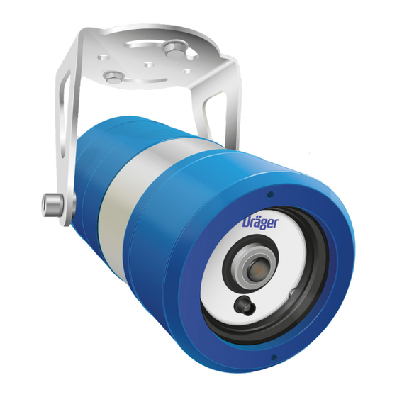
- Page 1 Dräger Flame 5000 Colour CCTV Visual Flame Detector Instructions for use Dräger Flame 5000...
- Page 2 This page has been left blank intentionally. Instructions for use Dräger Flame 5000...
-
Page 3: Table Of Contents
Contents Contents Dräger Flame 5000 For your safety................. Meaning of the warning notices..........Strictly follow the Instructions for Use ........Intended use ................Limitations on use ..............Understanding the system............Response characteristics ............Installation................Mechanical installation ............... Electrical installation..............Installation check-points ............. -
Page 4: For Your Safety
Warning sign Signal word Classification of the warning notice oxygen-enriched atmosphere. The purpose of the Dräger Flame 5000 is to detect a flame or fire. It may be WARNING Indicates a potentially hazardous situa- installed in areas that contain potentially explosive atmospheres, thus it is vital tion. -
Page 5: Intended Use
During system tests or maintenance, it is important that any control equipment is inhibited to avoid unwanted actuation or alarms. Dräger Flame 5000 is intended for use in an area which may contain potentially The following factors should also be taken into consideration: explosive atmosphere to detect a flame or fire. -
Page 6: Response Characteristics
0.1 m (1 ft Ethylene Glycol 0.1 m (1 ft ) pan 15 m (50 ft) Crude Oil 0.25 m (2.7 ft ) pan 40 m (130 ft) Instructions for use Dräger Flame 5000... -
Page 7: Installation
Ensure that any power is switched off before connecting any cabling to the flame detector. The connections are made in the rear terminal compartment through suitably certified glands. Instructions for use Dräger Flame 5000... - Page 8 The detector enclosure is to be connected to a local earth and the detector cable screens (shields) should be cut back to the crotch and not terminated within the detector. If the detector enclosure cannot be connected to a local Instructions for use Dräger Flame 5000...
- Page 9 1 and 2 is reversed, these wires then provide a RS485 connection to 485B RS485 termination -Ve the detector. This connection may then be used to upload or download information to the detector. Instructions for use Dräger Flame 5000...
- Page 10 485B RS485 termination -Ve Default 4-20 mA settings Event Output Power/detector fault 0 mA Optical fault 2 mA Healthy condition 5 mA Alarm 18 mA Over range 21 mA Instructions for use Dräger Flame 5000...
-
Page 11: Installation Check-Points
● The detector requires a clear unobstructed view of the local hazard. In order ● When locating the Dräger Flame 5000 consideration should be given to to avoid local obstructions, such as pipe-work and cable trays, a 2 m maintenance access to the detector and should allow for easy detector (6.56 ft) helix should be allowed in the detector cabling. -
Page 12: Operation
Flame Detector 5000 Detector 5000 Status indicators The detector LED indicator is used to reveal the current status of the Dräger Flame 5000, as shown below: LED status diagnostic chart LED colour Status indicator Maintenance Steady off No power Green... -
Page 13: How To Dispose Of The Instrument
Approximately 7 seconds (maximum 30 seconds) Humidity 5-95 % relative humidity IP rating IP 66, NEMA 4X Supply voltage 18 to 32 VDC (nominal 24 VDC) Power consumption 6 W (max. 15 W with heater) Instructions for use Dräger Flame 5000... -
Page 14: Order List
21.1 Dräger Flame 5000, 3/4 NPT, Relay, NTSC, Stainless Steel 420 93 22 Dräger Flame 5000 is a Type B element. Therefore, based on the Safe Failure Dräger Flame 5000, 3/4 NPT, 4-20 mA, PAL, Stainless Steel 420 93 23 Fraction SFF of 90 % a design it can meet SIL 2 @ HFT=0 when the product is used as the only component in a SIF sub-assembly. - Page 15 Part number Dräger Flame 5000, 3/4 NPT, 4-20 mA, NTSC, Stainless Steel 420 93 56 Dräger Flame 5000, 3/4 NPT, Relay, PAL, Stainless Steel 420 93 57 Dräger Flame 5000, M25, 4-20 mA, NTSC, Stainless Steel 420 93 58 Dräger Flame 5000, M20, Relay, PAL, Stainless Steel...
- Page 16 Distributor Importer (EU) Dräger Safety UK Limited Dräger Safety AG & KGaA Ullswater Close Revalstraße 1 Blyth, NE24 4RG 23560 Lübeck United Kingdom Germany Tel: +44 1670 352 891 Fax: +44 1670 356 266 4209337 – 4800.006 en © Dräger Safety AG & Co. KGaA Edition: 5 –...
Need help?
Do you have a question about the Flame 5000 and is the answer not in the manual?
Questions and answers