Advertisement
Quick Links
Advertisement

Related Manuals for Keysight Technologies M9170A


Summary of Contents for Keysight Technologies M9170A
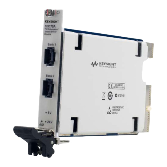
- Page 1 Keysight Technologies M9170A PXI Attenuator/Switch Driver Demo Guide...
- Page 2 – Intuitive configuration for all Keysight switches and attenuators This demonstration guide is intended for engineers who wish to learn about the capability and key features of the M9170A. Therefore, it assumes you have basic knowledge of PXI standards and programming. This document provides an overview of the M9170A, and guides you through a step-by-step measurement procedure to quickly configure a switch or attenuator for a PXI system.
- Page 3 Click on Visit Technical Support at the top section of the page iii. Click on Drivers, Firmware & Software tab. iv. Click on M9170A PXI Attenuator/Switch Driver Instrument Drivers and then click on the Download icon on the next page.
- Page 4 Connect peripherals (mouse, keyboard, and monitor) iii. Power up the chassis Refer to the M9170A configuration guide 5991-0052EN to choose switches and attenuators that are compatible with the M9170A module. Example: 87104B (Option 161) match with assembly cable M9170-601.
- Page 5 M9170A Module Installation Install the M9170A PXI module into the PXI chassis (one slot). Figure 2 block diagram shows cable connections for the M9170A demo. 1. Make sure the chassis power switch is in the Off (Standby) position and unplug the PXI chassis.
- Page 6 Figure 3. Embedded controller connection NOTE: The laptop or embedded controller has been pre-installed with all the software and configurations required to run this demonstration.
-
Page 7: Starting The Demo
Starting the Demo The demo equipment must be turned on between the computer and the instrument. The connection should be properly established. Bank 1 and Bank 2 provide two independent banks of switch and attenuator drive outputs. Click the Switch or Attenuator button and select a device model from the drop-down list. - Page 8 Click on the port according to desired switching path and measure the input and output RF port of that path. 2. If you select switch model 87222x, you can turn on or off the switches by clicking their respective port buttons. Below is an example: –...
- Page 9 Click on the port according to the desired switching path and measure the input and output RF port of that path. 4. If you select an attenuator model, you can select the attenuation level by clicking the respective level buttons. The selected level will be displayed in the Total Atten (dB) field.
-
Page 10: Appendix 1: Sfp Simulation Mode
Summary By following the procedures in this demo guide, you will be able to see the functionality of the M9170A to drive switches and attenuators externally. This guide also applies to chassis from other PXI vendors, as well as compatibility with most PXI programming software. -
Page 11: Appendix 2: Assembly Cable
Keysight M9021A Gen 2, x8 PCIe Cable Interface Module Installation, part number M9021-90001 Keysight M9018A PXIe Chassis data sheet, part number 5990-6583EN M9170A PXI Attenuator/Switch Driver Module, configuration guide, part number 5991-0052EN M9170A PXI Attenuator/Switch Driver Module, data sheet, part number 5991-0130EN... - Page 12 12 | Keysight | M9170A PXI Attenuator/Switch Driver - Demo Guide For more information on Keysight myKeysight Technologies’ products, applications or www.keysight.com/find/mykeysight services, please contact your local Keysight A personalized view into the information most relevant to you. office. The complete list is available at: www.keysight.com/find/contactus...
Need help?
Do you have a question about the M9170A and is the answer not in the manual?
Questions and answers