Table of Contents
Advertisement
Quick Links
Operator's Manual
®
Aqua TROLL
400 Instrument
Information subject to change without notice. In-Situ, In-Situ logo, Baro Merge, BaroTROLL, HERMIT, HydroVu™, iSitu, Pocket-Situ, RDO,
©
RuggedCable, RuggedReader, SmarTROLL™, TROLL, VuSitu, and Win-Situ are trademarks or registered trademarks of In-Situ Inc.
2012-
0088302 | 2018-05-15
2015. All rights reserved. This product may be covered by patents identified at www.in-situ.com/patents
Advertisement
Table of Contents

Related Manuals for In-situ Aqua Troll 400


Summary of Contents for In-situ Aqua Troll 400
- Page 1 Operator's Manual ® Aqua TROLL 400 Instrument Information subject to change without notice. In-Situ, In-Situ logo, Baro Merge, BaroTROLL, HERMIT, HydroVu™, iSitu, Pocket-Situ, RDO, © RuggedCable, RuggedReader, SmarTROLL™, TROLL, VuSitu, and Win-Situ are trademarks or registered trademarks of In-Situ Inc. 2012- 0088302 | 2018-05-15 2015.
-
Page 2: Cleaning Procedure
Apple Inc., registered in the U.S. and other countries. The Bluetooth word mark and logos are registered trademarks owned by the Bluetooth SIG, Inc. and any use of such marks by In-Situ Inc. is under license. NIST is a registered trademark of the National Institute of Standards and Technology, U.S.A. -
Page 3: Table Of Contents
Modbus Setup SDI-12 Setup View and Record Data Calibrate and Set Up Sensors Calibration Frequency Recommendations Factory Calibration Set Parameter Units and Sentinel Values RDO Sensor Calibration Calibration 100% Oxygen Saturation Calibrate 0% Oxygen Saturation Conductivity Calibration Pressure/Level 800-446-7488 www.in-situ.com... -
Page 4: Cleaning Procedure
Remove Protein-Like Material or Slimy Film Cleaning the RDO Sensor Clean the Sensor Cap Clean the Optical Window Cleaning the Conductivity Sensor Cleaning Procedure 1 Cleaning Procedure 2 Cleaning Procedure 3 Cleaning Procedure 4 11 Declaration of Conformity 800-446-7488 www.in-situ.com... -
Page 5: Introduction
Introduction This manual is intended to describe the characteristics, operation, calibration, and maintenance of the Aqua TROLL 400 Instrument. Communication registers and programming information can be found in the Modbus and SDI-12 Reference Guide. Scope This manual covers the following information. -
Page 6: General Specifications
Measurement current: 16 mA @ 24 VDC. Sleep current: 40 µA @ 24 VDC ® ® In-Situ Con TROLL PRO System; In-Situ TROLL Link Telemetry 101 or 201 System; SCADA/PLC; and Interface third-party data loggers, samplers, controllers, and telemetry systems. -
Page 7: Sensor Specifications
0.1 μS/cm Sensor Type Fixed Response Instantaneous in thermal equilibrium Time Actual conductivity (μS/cm, mS/cm) Specific conductivity (μS/cm, mS/cm) Units of Salinity (PSU) Measure Total dissolved solids (ppt, ppm) Resistivity (Ohms-cm) Density (g/cm3) Methodology Std. Methods 2510 EPA 120.1 800-446-7488 www.in-situ.com... -
Page 8: Rdo (Optical Dissolved Oxygen Sensor) Specifications
Fixed with replaceable RDO Sensor Cap (life: 1 year Sensor Type typical) Response T90: <45 sec. T95: <60 sec. Time Units of mg/L, % saturation, ppm Measure EPA-approved In-Situ Methods 1002-8-2009 1003-8-2009 Methodology 1004-8-2009 ORP Sensor Specifications Accuracy ±5.0 mV Range ±1400 mV Resolution 0.1 mV... -
Page 9: Ph Sensor Specifications
Temperature Sensor Specifications (Probe) Accuracy ±0.1° C Range -5 to 50° C (23 to 122° F) Resolution 0.01° C or better Sensor Type Fixed Response <30 sec.; temperature sensor only Time Units of Celsius, Fahrenheit Measure Methodology EPA 170.1 800-446-7488 www.in-situ.com... -
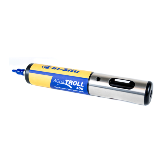
Page 10: Instrument Overview
Instrument Overview Instrument Description The Aqua TROLL 400 Instrument is a multiparameter water quality probe. The dissolved oxygen, conductivity, pressure, and temperature sensors are integrated into the instrument. The pH/ORP sensor and the RDO Sensor Cap are replaceable. The instrument is intended for use with a PLC/SCADA system or other data-logging device. It does not include internal power or an internal data logger. -
Page 11: Probe Dimensions With Restrictor On
Total length with connector 296.49 mm (11.7 in.) Total length without connector 269.11 mm (10.6 in.) Restrictor length 118.24 mm (4.7 in.) Diameter 47 mm (1.85 in.) Probe Dimensions with Restrictor Off Sensor length 81.09 mm (3.2 in.) 800-446-7488 www.in-situ.com... -
Page 12: Sensors
Win-Situ 5 Software The Win-Situ 5 Software is used to calibrate the sensors and to configure the instrument settings to communicate with a process controller or data logger. See the Communication Settings and Calibration section for more details. 800-446-7488 www.in-situ.com... -
Page 13: Probe Setup
Dust cap protector on the RDO Sensor. (Install the RDO Cap before deploying the instrument.) pH/ORP storage plug. (Remove the storage plug and install the pH/ORP sensor before deploying the instrument.) Dust cap protector on the twist-lock cable connector. 800-446-7488 www.in-situ.com... -
Page 14: Installing The Sensors
Important: Avoid touching the sensor lens and the sensing material on the top of the cap. Important: The RDO Sensor Cap and pH/ORP sensor must be installed firmly in place to prevent water from entering the instrument. 800-446-7488 www.in-situ.com... -
Page 15: Communication Settings And Calibration
Aqua TROLL 400 to a computer running Win-Situ 5 Software version 5.6.22 or later. Connect the Instrument to Win-Situ 5 Software Install Win-Situ 5 Software from the Resources CD or from www.in-situ.com. Make sure you select the check box that installs the USB drivers. -
Page 16: Data Tab
The Logging tab displays a list of logs stored in the connected instrument. When you click the Logging tab, it can take a moment for the software to retrieve information from the instrument. (Not applicable for the RDO PRO-X and the Aqua TROLL 400.) 800-446-7488 www.in-situ.com... -
Page 17: Set Communication Outputs
The Device Setup Tab allows you to access communication settings, instrument information and status, factory reset, diagnostics, and alarm setup. The instrument can communicate via Modbus or SDI-12 protocols. However, the instrument can use only one of the protocols at a time. 800-446-7488 www.in-situ.com... -
Page 18: Modbus Setup
Modbus Setup Click the Modbus setup button and assign instrument settings according to the requirements of your controller. For instrument Modbus registers, see the Modbus and SDI-12 Reference Guide. 800-446-7488 www.in-situ.com... -
Page 19: Sdi-12 Setup
SDI-12 setup allows you to set the instrument address, select the parameters you intend to log, and select the order in which the parameters will appear in your SCADA system or datalogger file. See the Help menu in Win-Situ 5 Software for details. To view SDI-12 programming information, see the Modbus and SDI-12 Reference Guide. 800-446-7488 www.in-situ.com... -
Page 20: View And Record Data
Definition The Sites button allows you to add, edit, or delete a site. (Not applicable for Aqua TROLL 400 and RDO PRO-X.) These icons allow you to view the memory and battery usage for an instrument that includes internal logging. (Not applicable for Aqua TROLL 400 and RDO PRO-X.) - Page 21 Click the Device Setup tab for detailed information on the alarm or warning. (Not applicable for Aqua TROLL 400 and RDO PRO-X.) System Time is displayed on the left. Device Time is displayed on the right. Clocks are updated once every two seconds. When the Device Time is displayed in red, it differs from the current System Time, and should be synchronized.
-
Page 22: Calibrate And Set Up Sensors
Calibration Frequency Recommendations In-Situ sensors are factory calibrated across the entire range of each sensor, and thus achieve a very high degree of accuracy and stability for extended periods of time without user calibration. In-Situ recommends inserting the instrument into a known calibration standard to check the accuracy of a sensor prior to performing any user calibration if you suspect drift, unless a user calibration is required by a standard operating procedure. -
Page 23: Factory Calibration
Factory calibration includes a thorough cleaning, full functionality check and sensor adjustments to all applicable sensors over the entire calibrated temperature range. We recommend a factory calibration every 12 months or when the unit appears to drift significantly. 800-446-7488 www.in-situ.com... -
Page 24: Set Parameter Units And Sentinel Values
This button becomes active when you select a parameter Configure that includes additional configuration options. Click the Configure button to view the additional options. Clicking the Check mark saves the changes you have Check mark made in this screen. 800-446-7488 www.in-situ.com... -
Page 25: Rdo Sensor Calibration
3. Gently dry the probe and sensing material with a paper towel. Ensure that the probe and the sensing surface are free of water and fouling. 4. Place the instrument into the calibration cup. 5. Wait 5 to 10 minutes for temperature stabilization prior to calibration. 800-446-7488 www.in-situ.com... -
Page 26: Calibrate 0% Oxygen Saturation
3. Fill the calibration cup to the fill line with approximately 130 mL of fresh sodium sulfite solution. 4. Gently place the instrument in the calibration cup, taking care to not force the solution out the top of the calibration cup. 800-446-7488 www.in-situ.com... - Page 27 Cancel to return to the previous calibration. 8. You can save or print the calibration report. 9. Click OK to complete the calibration. 10. Once calibration is complete, remove the instrument from the calibration cup and rinse both thoroughly with clean water. 800-446-7488 www.in-situ.com...
-
Page 28: Conductivity Calibration
3. In Win-Situ 5 Software, select the Conductivity sensor. 4. Click the Calibrate button in the left corner of the screen. 5. Select either 20° C or 25° C as the reference temperature, as indicated by the reference calibration solution. 800-446-7488 www.in-situ.com... -
Page 29: Pressure/Level
For best results, use the pressure sensor to measure Surface Elevation or Depth to Water. pH/ORP Calibration We recommend calibrating the pH/ORP sensor after you perform cleaning and maintenance or every two to six weeks. 800-446-7488 www.in-situ.com... - Page 30 2. Place the calibration cap on the instrument slightly above the restrictor, and place the instrument in the solution taking care to not force the solution out the top of the calibration cup. 3. In Win-Situ 5 Software, select the pH/ORP sensor. 4. Click the Calibrate button in the left corner of the screen. 800-446-7488 www.in-situ.com...
- Page 31 12. Follow the Wizard to continue through the remaining calibration points. 13. You can save or print the calibration report. 14. Click OK to complete the calibration. 15. Once calibration is complete, remove the instrument from the calibration cup and rinse both thoroughly with clean water. 800-446-7488 www.in-situ.com...
-
Page 32: Controller Requirements And Connections
Power Connections The Aqua TROLL 400 requires an external 8 to 36 VDC power source. The red wire must be connected to the positive terminal of the power source. The black wire must be connected to the negative terminal of the power source, which is often referred to as the system ground or return. -
Page 33: Sdi-12 Wiring Diagram
SDI-12 Wiring Diagram Cable length must not exceed 60.9 m (200 ft). Signal Color Ground/Return Black External Power (9.6-16 VDC) SDI-12 White 800-446-7488 www.in-situ.com... -
Page 34: Modbus Master Rs485 Wiring Diagram
Modbus Master RS485 Wiring Diagram Cable length must not exceed 1,219 m (4,000 ft). Signal Color Ground/Return Black External Power (12-36 VDC) RS485 (-) Green RS485 (+) Blue 800-446-7488 www.in-situ.com... -
Page 35: Modbus Master Rs232 Wiring Diagram (Converter Required)
Cable length between Master and Slave must not exceed 1,219 m (4,000 ft). Cable length between Master and Converter must not exceed 6 m (20 ft). Signal Color Ground/Return Black External Power (12-36 VDC, voltage limited by converter) RS485 (-) Green RS485 (+) Blue 800-446-7488 www.in-situ.com... -
Page 36: Rs485 Network Guidelines
Data Quality IDs and the Sensor Health Table Each sensor on the Aqua TROLL 400 instrument is associated with a corresponding Data Quality ID register. (See the Aqua TROLL 400 Modbus and SDI-12 Guide to set up registers.) When Data Quality ID registers are configured, they will return Data Quality ID numbers that can help you to troubleshoot issues with the system or verify that readings are normal. -
Page 37: Sensor Health Table
Warning damage, or the recommended lifespan has been reached. Sensor Sensor is calibrating, calibration Calibrating value supplied. Sensor communication failed, sentinel value supplied. Make sure Sensor Missing the sensor cap is installed and properly seated. 800-446-7488 www.in-situ.com... -
Page 38: Care And Maintenance
The RDO Sensor Cap has a 1-year typical life (15 months of total usage) after the sensor takes its first reading, or 36 months from the date of manufacture. Follow the instructions included in the RDO Sensor Cap Replacement Kit. Replacement caps are available from In-Situ Inc. or your authorized In-Situ distributor. pH/ORP Sensor Replacement To replace the pH/ORP sensor or to refill the reference junction, follow the instructions in the pH/ORP Sensor Instruction Sheet that is included with the replacement sensor. -
Page 39: Cleaning The Ph/Orp Sensor
Clean the Sensor Cap 1. Leave the cap on the sensor. 2. Rinse the sensor with clean water from a squirt bottle or spray bottle. 3. Gently wipe with a soft cloth or brush if biofouling is present. 800-446-7488 www.in-situ.com... -
Page 40: Clean The Optical Window
Process 3. Do not allow the cleaner to be in contact with the sensor for more than 10 minutes. Rinse well with clean water and continue to the last step. Check the sensor calibration before redeployment. Recalibrate the sensor when necessary. 800-446-7488 www.in-situ.com... -
Page 41: Declaration Of Conformity
Declaration of Conformity 800-446-7488 www.in-situ.com...
Need help?
Do you have a question about the Aqua Troll 400 and is the answer not in the manual?
Questions and answers