Table of Contents
Advertisement
Quick Links
RDO Pro-X
Operator's Manual
Information subject to change without notice. In-Situ, In-Situ logo, "Water Simplified", VuLink, RDO, RuggedCable, TROLL,
BaroTROLL, HydroVu, VuSitu, Baro Merge, and Win-Situ are trademarks or registered trademarks of In-Situ Inc. ©2023. All
2023-10-11 | 0090102
rights reserved. This product may be covered by patents identified at www.in-situ.com/patents
Advertisement
Table of Contents

Related Manuals for In-situ RDO Pro-X


Summary of Contents for In-situ RDO Pro-X
- Page 1 Operator’s Manual Information subject to change without notice. In-Situ, In-Situ logo, “Water Simplified”, VuLink, RDO, RuggedCable, TROLL, BaroTROLL, HydroVu, VuSitu, Baro Merge, and Win-Situ are trademarks or registered trademarks of In-Situ Inc. ©2023. All 2023-10-11 | 0090102 rights reserved. This product may be covered by patents identified at www.in-situ.com/patents...
- Page 2 Apple Inc., registered in the U.S. and other countries. The Bluetooth word mark and logos are registered trademarks owned by the Bluetooth SIG, Inc. and any use of such marks by In-Situ Inc. is under license. NIST is a registered trademark of the National Institute of Standards and Technology, U.S.A.
-
Page 3: Table Of Contents
Contents Optical RDO PRO-X Dissolved Oxygen Probe Specifications ���������������������������������������������������������������������� 5 Optical RDO PRO-X Dissolved Oxygen Probe ........................5 Introduction ���������������������������������������������������������������������������������������������������������������������������������������������������� 6 System Description ..................................6 Serial Numbers ....................................7 Unpack the Probe ..................................7 Calibrate the RDO PRO-X Probe �������������������������������������������������������������������������������������������������������������������� 9 1-Point Calibration .................................. - Page 4 Connect the Probe to the Communication Device......................24 Service ����������������������������������������������������������������������������������������������������������������������������������������������������������� 24 RDO Software Troubleshooting ..............................24 Declaration of Conformity ��������������������������������������������������������������������������������������������������������������������������� 25 Appendix ������������������������������������������������������������������������������������������������������������������������������������������������������ 27 Appendix A: Parameter Numbers and Locations ......................27 Appendix B: Unit IDs ...................................27 Appendix C: Calibration Registers............................28 1-970-498-1500 www.in-situ.com...
-
Page 5: Optical Rdo Pro-X Dissolved Oxygen Probe Specifications
Optical RDO PRO-X Dissolved Oxygen Probe Specifications Optical RDO PRO-X Dissolved Oxygen Probe Sensor Type Optical (luminescent) dissolved oxygen sensor Range: 0 to 60 mg/L concentration Accuracy: ±0.1 mg/L from 0 to 20 mg/L ±2% of reading from 20-60 mg/L RDO PRO-X Probe Resolution: 0.01 mg/L... -
Page 6: Introduction
Introduction The RDO PRO-X Probe is a rugged, reliable instrument designed to deliver accurate dissolved oxygen (DO) data across a wide measurement range and to reduce maintenance costs. The probe features the latest optical technology for DO measurement. System Description The RDO PRO-X system consists of the following items. -
Page 7: Serial Numbers
3. Remove the RDO cap from the storage sleeve. 4. Align the arrow on the cap with the index mark on the probe and firmly press the cap onto the probe, without twisting, until it seals over the probe body. 1-970-498-1500 www.in-situ.com... - Page 8 Install promptly. Ensure that O-ring grooves are dry and that the O-ring is not rolled or pinched inside the cap. The typical cap lifetime is two years after the first reading has been taken. 5. Reattach the nose cone. 1-970-498-1500 www.in-situ.com...
-
Page 9: Calibrate The Rdo Pro-X Probe
Calibrate the RDO PRO-X Probe Calibrate the sensor with Win-Situ 5 software or the VuSitu mobile app, or calibrate directly with your controller. 1-Point Calibration The optical Rugged Dissolved Oxygen sensor is very stable. The factory calibration should produce readings within 3% accuracy. -
Page 10: 2-Point Calibration
4. Ensure that the temperature sensor is completely submerged in the solution. 5. Allow at least 5 minutes for the temperature to stabilize prior to performing the calibration procedure. 6. Once calibration is complete, remove the sensor, and thoroughly rinse to remove all of the sodium sulfite. 1-970-498-1500 www.in-situ.com... -
Page 11: Probe Deployment
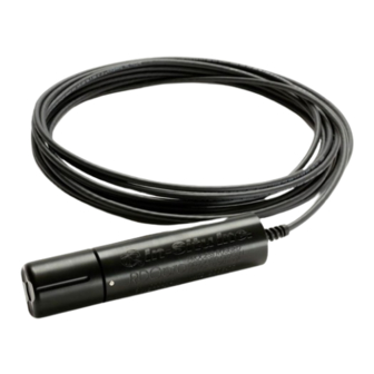
Probe Deployment The cable end of the RDO PRO-X Probe is internally threaded (1¼ – 11½ NPT) and can be attached to a male threaded pipe. When deployed, make sure that the nose cone and thermistor are completely submerged. 10 m cable attached... -
Page 12: Care And Maintenance
5. Use your finger to apply a very light layer of silicone-based lubricant around the O-ring grooves. 6. Place the O-rings on the sensor. Apply another thin layer of lubricant to the O-rings and grooves. 1-970-498-1500 www.in-situ.com... -
Page 13: Maintain Desiccant
It is extremely important to use the proper size desiccant for your deployment and to change desiccant often. Desiccant should be changed before the entire pack has turned pink, and you should use enough to effectively keep cables and probes dry until your next scheduled maintenance. Desiccant lifespan is dependent on site conditions. 1-970-498-1500 www.in-situ.com... -
Page 14: Controller Requirements And Connections
Controller Requirements and Connections The RDO PRO-X Probe may be connected to a controller or logger for communication via the following options. • Analog (4-20 mA) provides a configurable 4-20 mA current loop output • SDI-12 • RS485 Modbus • RS232 to Modbus Wire Diagram Refer to the diagrams on the following pages for PLC wiring diagrams. -
Page 15: Power Connections
Win-Situ 5. Analog output can be enabled with a PLC by setting Modbus device register 9507 to 1. Analog (4-20 mA) wiring diagram Maximum cable length is 4000 ft Analog must be enabled in VuSitu or the Comm Kit Software 1-970-498-1500 www.in-situ.com... -
Page 16: Sdi-12 Wiring Diagram
SDI-12 wiring diagram Cable length must not exceed 60.96 m (200 ft.) 1-970-498-1500 www.in-situ.com... -
Page 17: Modbus (Rs485) Wiring Diagram
Modbus (RS485) wiring diagram Cable length must not exceed 1219 m (4000 ft.) 1-970-498-1500 www.in-situ.com... -
Page 18: Modbus (Rs232 With Converter) Wiring Diagram
Modbus (RS232 with converter) wiring diagram Cable between converter and master must not exceed 60.96 m (20 ft.) Cable between master and slave must not exceed 1219 m (4000 ft.) Converter 1-970-498-1500 www.in-situ.com... -
Page 19: Configuring Sdi-12 Settings
Modbus PLC Interface Overview The Modbus PLC Interface is a simplified method of communicating with the RDO Pro-X using the Modbus protocol. For information about the specific Modbus registers and Unit IDs for your RDO Pro-X, see Appendices A and B. The RDO Pro-X conforms to the Modbus standard. For more information about Modbus communication, see www.modbus.org. -
Page 20: Setting Up Instrument
Use the following registers to read general information about the instrument. Holding Register Holding Register Size Data Description Number Address (Registers) Type 9001 9000 uint16 Device Id: 31 = RDO Pro-X 9002 9001 uint32 Serial Number 9007 9006 uint16 Firmware version (100 = 1.00) 1-970-498-1500 www.in-situ.com... -
Page 21: Reading Parameters
Units ID as shown in Appendix B. For example, if register number 0041 (DO Concentration Units ID) returns 117, DO Concentration is configured to report in mg/L. Looking at Appendix B, you can find that μg/L is also a valid unit which can be set by writing Units ID 118 to register number 0041. 1-970-498-1500 www.in-situ.com... -
Page 22: Dissolved Oxygen Equations
Dissolved Oxygen Equations Dissolved Oxygen Concentration DO concentration is internally calculated in mg/L. Conversion to other units is as follows: 1-970-498-1500 www.in-situ.com... -
Page 23: Dissolved Oxygen, % Saturation
Dissolved Oxygen, % Saturation 1-970-498-1500 www.in-situ.com... -
Page 24: Communication Device
3. Attach the USB connector to a USB port on the computer. Follow the directions provided in the Communication Device Kit to set up the probe. Service The RDO PRO-X contains no user-serviceable parts. Do not attempt to open the probe case or service the unit yourself. RDO Software Troubleshooting Sensor health diagnostics indicate when the RDO sensor has been damaged in the field. -
Page 25: Declaration Of Conformity
Model Variants: There are two models of the RDO Pro-X and they differ by their connection type: one has an integrated cable which terminates in stripped and tinned wires and one has a twist-lock backend to accommodate an external TL cable. - Page 26 Model Variants: There are two models of the RDO Pro-X and they differ by their connection type: one has an integrated cable which terminates in stripped and tinned wires and one has a twist-lock backend to accommodate an external TL cable.
-
Page 27: Appendix
Oxygen Partial 0062 0061 26 = torr Pressure Appendix B: Unit IDs Abbreviation Units Temperature Celsius Fahrenheit Pressure torr Torr Concentration mg/L Milligrams per liter μg/L Milligrams per liter Dissolved Oxygen (DO) % Saturation % sat Percent saturation 1-970-498-1500 www.in-situ.com... -
Page 28: Appendix C: Calibration Registers
This is not a measured parameter. 100% Saturation Calibration Values These values represent the sensor conditions while the probe is in a 100% saturation calibration environment. These are not measured values, they are written by the controller during the calibration process. 1-970-498-1500 www.in-situ.com... - Page 29 11. Optional: Read the last user calibration time register, add the next calibration interval, and write the result to the next user calibration time register. 12. Write the Calibration Mode Off command (0xE002) to the sensor command register to place the 1-970-498-1500 www.in-situ.com...
- Page 30 13. Optional: If you saved the temperature and saturation parameter units at the start of the process, write the original values back. 14. Optional: If you saved the Sensor Data Cache Timeout register 9463 at the start of the process, write the original value back. Calibration Calculations 1-970-498-1500 www.in-situ.com...
Need help?
Do you have a question about the RDO Pro-X and is the answer not in the manual?
Questions and answers