In-situ Aqua TROLL 600 Operator's Manual
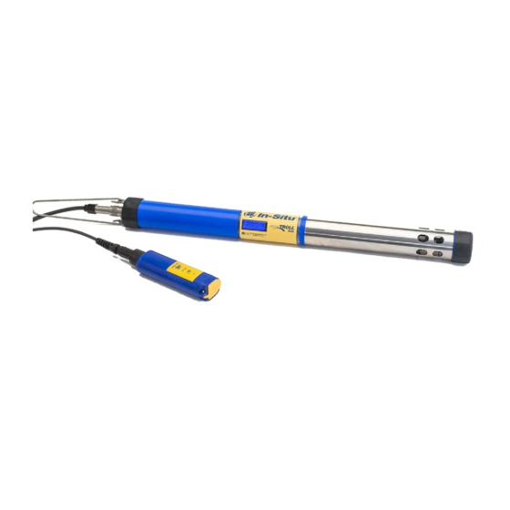
Multiparameter sonde
Hide thumbs
Also See for Aqua TROLL 600:
- Operator's manual (138 pages) ,
- Quick start manual (4 pages) ,
- Instruction sheet (3 pages)
Table of Contents
Advertisement
Quick Links
Operator's Manual
®
Aqua TROLL
600 Multiparameter Sonde
Part Number 0096400
Information subject to change without notice. In-Situ, In-Situ logo, Baro Merge, BaroTROLL, HERMIT, HydroVu™, iSitu, Pocket-Situ, RDO,
©
RuggedCable, RuggedReader, SmarTROLL™, TROLL, VuSitu, and Win-Situ are trademarks or registered trademarks of In-Situ Inc.
2016.
0096402 | Rev. 002 | 04/2016
All rights reserved.
Advertisement
Table of Contents

Related Manuals for In-situ Aqua TROLL 600


Summary of Contents for In-situ Aqua TROLL 600
- Page 1 Aqua TROLL 600 Multiparameter Sonde Part Number 0096400 Information subject to change without notice. In-Situ, In-Situ logo, Baro Merge, BaroTROLL, HERMIT, HydroVu™, iSitu, Pocket-Situ, RDO, © RuggedCable, RuggedReader, SmarTROLL™, TROLL, VuSitu, and Win-Situ are trademarks or registered trademarks of In-Situ Inc.
- Page 2 Support: 800-446-7488 (U.S.A. & Canada) In-Situ makes no warranty of any kind with regard to this material, including, but not limited to, its fitness for a particular application. In-Situ will not be liable for errors contained herein or for incidental or consequential damages in connection with the furnishing, performance, or use of this material.
-
Page 3: Table Of Contents
Sensor Specifications Temperature Sensor Specifications Turbidity Sensor Specifications Total Suspended Solids 4 Instrument Overview Synopsis System Components Base Unit Components Accessories purchased separately. RuggedCable System Vented or Non-Vented Cable Jacket Options Customizable Cable Lengths Cable Termination 5 Instrument Setup 1-970-498-1500 www.in-situ.com... - Page 4 Contrast Menu Language Menu Updates Menu 8 Batteries Battery Replacement 9 Micro SD Card Removing the Micro SD Card Downloading and Deleting Data from the Micro SD Card Updating Firmware 10 Desiccant Replace the Desiccant 11 Sensor Calibration 1-970-498-1500 www.in-situ.com...
- Page 5 Preparing the Aqua TROLL 600 for Calibration Calibration Recommendations Factory Calibration 12 Software 13 VuSitu Mobile App Verify the VuSitu Mobile App Version Connecting with Bluetooth VuSitu Overview About VuSitu VuSitu Menu Options Menu Options when Connected to Instrument Live Readings Screen...
- Page 6 Exporting Data to Spreadsheet Format Exporting to Text Graphing Data View a Graph of a Downloaded File View a Graph of Real-Time Data Graph Settings Graph Templates Graph Tools Calibration Calibrate Sensors Calibrating the Conductivity Sensor Calibrating the Pressure Sensor 1-970-498-1500 www.in-situ.com...
- Page 7 About Post Correcting Level Data Open Post Level Correction Select Level Reference Type Set the Level Correction View Post Level Corrected Data Win-Situ 5 Troubleshooting Selecting the Correct COM Port Bluetooth Connection 15 Water Quality What is pH? Why Measure pH? 1-970-498-1500 www.in-situ.com...
- Page 8 Long-term Storage (>1 Week) Cleaning the Sonde Cleaning and Storing the pH/ORP Sensor Routine Maintenance Replacing the Filling Solution Replacing the Junction Cleaning Short-term Storage Long-term Storage Storage Recommendations Cleaning and Storing the RDO Sensor Routine Maintenance Cleaning the Optical Window 1-970-498-1500 www.in-situ.com...
- Page 9 Storage Cleaning and Storing the Conductivity Sensor Cleaning Storage Cleaning and Storing the Turbidity Sensor Routine Maintenance Storage Replacing Wiper Bristles Replace the Bristles Replace the Entire Brush Cleaning the Copper Antifouling Restrictor 17 Declaration of Conformity 1-970-498-1500 www.in-situ.com...
-
Page 10: Introduction
RDO Sensor Cap are replaceable. It is optional to include a motorized sensor wiper on the instrument. The Aqua TROLL 600 can connect wirelessly via Bluetooth to the VuSitu Mobile App or can connect to Win-Situ 5 Software using cable or Bluetooth. -
Page 11: Obtaining Repair Service
If you suspect your system is malfunctioning and repair is needed, you can help assure efficient servicing by following these guidelines: 1. Call or email In-Situ Technical Support. Have the product model and serial number available. 2. Be prepared to describe the problem, including how the product was used and the conditions noted at the time of the malfunction. - Page 12 We recommend the glassware cleaning product, Alconox, available from In-Situ and from laboratory supply companies. Clean all cables and remove all foreign matter. Clean the cable connectors with a clean, dry cloth. Do not submerge the connectors. Clean the instrument including the nosecone, cable head, and protective caps.
-
Page 13: Decontamination And Cleaning Form
Ensure that the RDO Sensor Cap is pressed firmly over the sensor lens and is flush with the instrument before submerging in liquid. Replace the cable if insulation or connectors are damaged. Make sure the probe and sensor O-rings are clean and free of damage. 1-970-498-1500 www.in-situ.com... -
Page 14: General Specifications
8-36 VDC, 275 mA maximum (not required) voltage External power Sleep: 0.10 mA typical current Measurement: 15 mA typical, 45 mA maximum Win-Situ 5 Software, VuSitu Mobile App on select Interface mobile devices using Android 4.4 with Bluetooth 2.0 1-970-498-1500 www.in-situ.com... - Page 15 2 year - sonde, sensors (excluding pH/ORP); Warranty 1 year - pH/ORP sensor Other - see warranty policy at www.in-situ.com Specifications are subject to change without notice. Android is a trademark of Google, Inc. Bluetooth is a trademark of Bluetooth SIG, Inc. Delrin and Tefzel are trademarks of E.I.
-
Page 16: Instrument Dimensions With Restrictor On
Shelf Field Temperature Depth Sensors Calibration Rating - Life Life* Range Frequency* Meters Feet 1 year pH/ORP 10 to 12 weeks - 5 to 50° C months greater 2 years 12 months - 5 to 50° C greater 1-970-498-1500 www.in-situ.com... -
Page 17: Barometric Pressure Sensor Specifications
- 5 to 50° C Pressure greater if needed * Field life and calibration frequency dependent on site conditions. See the Aqua TROLL 600 specification sheet for sensor specifications. Barometric Pressure Sensor Specifications Accuracy ±1.0 mbar Range 300 to 1,100 mbar Resolution 0.1 mbar... -
Page 18: Total Dissolved Solids
±10% of reading from 20 to 50 mg/L 0 to 8 mg/L 8 to 20 mg/L Range 20 to 50 mg/L Full operating range: 0 to 50 mg/L; 0 to 500% saturation Resolution 0.01 mg/L Sensor Type Removable with replaceable RDO-X Cap 1-970-498-1500 www.in-situ.com... -
Page 19: Level, Depth, Pressure Sensor Specifications
Response RDO-X Cap: T63<15s, T90<45s, T95<60s Time Units of mg/L, % saturation, ppm Measure EPA-approved In-Situ Methods (under the Alternate Test Methodology Procedure process): 1002-8-2009, 1003-8-2009, 1004-8- 2009 Level, Depth, Pressure Sensor Specifications Accuracy Typical ±0.1% full scale (FS) Non-vented or Vented 9.0 m (30 ft) - Burst: 27 m (90 ft) -
Page 20: Orp Sensor Specifications
Measure Methodology Std. Methods 4500-H+, EPA 150.2 *At thermal equilibrium. Temperature Sensor Specifications Accuracy ±0.1° C Range -5 to 50° C (23 to 122° F) Resolution 0.01° C Sensor Type Replaceable Response T63<2s, T90<15s, T95<30s Time 1-970-498-1500 www.in-situ.com... -
Page 21: Turbidity Sensor Specifications
Sensor Type Replaceable Response T63<1s, T90<1s, T95<1s Time Units of NTU, FNU Measure Methodology ISO 7027 Total Suspended Solids TSS is derived from turbidity. Range 0 to 1,500 mg/L Resolution 0.1 mg/L Units of ppt, mg/L Measure User-defined reference. 1-970-498-1500 www.in-situ.com... -
Page 22: Instrument Overview
The instrument’s outside diameter (OD) allows the instrument to conform to a 2-in./5.08 cm diameter (or larger) well. The Aqua TROLL 600 is recommended for applications like ambient long-term water quality monitoring in fresh and marine environments;... -
Page 23: System Components
Cable Stripped-and-tinned Cable with male connector 0053310 Twist-Lock Bulkhead Connector 0053240 Twist-Lock Backshell / Hanger, Titanium 0051480 Cable Extender 0051490 Large Desiccant (titanium connector) 0051810 Large Desiccant (ABS connector) 0053550 Small Desiccant (3 pack) - storage desiccant 0052230 1-970-498-1500 www.in-situ.com... - Page 24 Individual Calibration Solutions See website Low-Flow Complete Low-Flow Kit (includes flow cell with fittings 0066820 and stake, base plate, documentation) Flow Cell Kit 0066830 Flow Cell Base Plate 0044430 Fittings Kit 0093480 Pelican Case with foam insert 0066860 1-970-498-1500 www.in-situ.com...
-
Page 25: Ruggedcable System
TROLL Com Communication Device, desiccant, and other accessories. Cables can also be ordered with stripped-and-tinned termination for wiring to a data logger or controller using SDI-12, analog (4-20 mA), or Modbus communication protocol. 1-970-498-1500 www.in-situ.com... - Page 26 RuggedCable System with female to female connectors Stripped-and-tinned RuggedCable System with female connector Stripped-and-tinned RuggedCable System with male connector (short length that converts a cable with a twist-lock connector to a stripped-and-tinned cable) 1-970-498-1500 www.in-situ.com...
-
Page 27: Instrument Setup
Wiper motor and brush or wiper port plug ® Aqua TROLL 600 Sonde Water quality sensors (2 of 4) Calibration cup Water quality sensors (2 of 4) RDO sensor cap Accessory supplies* pH/ORP sensor maintenance supplies Extra sensors (0 to 2) 1-970-498-1500 www.in-situ.com... -
Page 28: Install The Batteries
2. On the opposite side of the batteries is a back-up Allen wrench that can be used for sensor installation and removal. 3. Check to see that the replaceable desiccant capsule is blue indicating it is fresh. Replace the desiccant if it is pink. 1-970-498-1500 www.in-situ.com... -
Page 29: Desiccant
Desiccant The Aqua TROLL 600 contains a small, replaceable desiccant capsule in the battery compartment. This capsule prevents moisture from causing damage to the electronic components. It is filled with color-indicating silica that gradually changes from purple to pink as the desiccant's effectiveness decreases. - Page 30 Sensor interlock tab The pH/ORP sensor is shipped with a storage cap taped on the sensor. Remove this cap before installation and save the cap for later storage. Salt crystals may form on pH/ORP sensors during storage. These 1-970-498-1500 www.in-situ.com...
-
Page 31: Removing Sensors
Note: The restrictor can be inverted to act as a storage cup when the instrument is not in use. See "Instrument Storage" on page 117. Removing Sensors 1. Loosen the sensor screw. 2. Insert the Allen wrench into the small hole at the base of the sensor. 1-970-498-1500 www.in-situ.com... -
Page 32: Connecting To The Sonde
1. If a desiccant is present, remove the desiccant from the cable. Twist the desiccant and cable sleeve in opposite directions to unlock the desiccant from the cable. 2. Position the TROLL Com and cable flat edges so they will connect properly. Push and twist until you hear a click. 1-970-498-1500 www.in-situ.com... -
Page 33: Connecting With Bluetooth
The Aqua TROLL 600 can connect to a Bluetooth-enabled device for wireless communication with the VuSitu Mobile App or Win-Situ 5. 1. Turn on the Aqua TROLL 600 LCD screen by holding the sonde vertical with the sensor end facing up. -
Page 34: Sdi-12 3 Wire
4. Click Preferences, then click Comm Settings. 5. Select the correct Com port used by the charging cable, then select the communication settings for the instrument you are connecting. The following default communication settings are most common for In-Situ instruments: Baud: 19200 Data Bits: 8... - Page 35 1-970-498-1500 www.in-situ.com...
-
Page 36: Modbus Master
Modbus Master 1-970-498-1500 www.in-situ.com... -
Page 37: Modbus Master With Rs232 (Converter Required)
Modbus Master with RS232 (Converter Required) LCD Screen LCD Screen The AquaTROLL 600 includes an LCD screen that allows you to view instrument status and access sonde settings. 1-970-498-1500 www.in-situ.com... -
Page 38: Turn On The Lcd Screen
Sensors are installed Battery level indicator Sensor Port Plugs are installed External power provided Battery error or Sensor error Battery below 10% Ports are open Possible Log Possible Connected Status Status Connected to software A log is running via Bluetooth 1-970-498-1500 www.in-situ.com... -
Page 39: Additional Lcd Icons
Wiper sensor port is open. Install wiper Install wiper or wiper port plug into center port. Sensor ports are open. Install sensors Install sensors or sensor port plugs. No Temperature or Conductivity/Temperature sensor detected. Install temperature Install a sensor with Temperature. 1-970-498-1500 www.in-situ.com... -
Page 40: Sonde Menus
2. Wait until the LCD screen displays the status icons. 3. Hold the sonde horizontally and firmly tap the Aqua TROLL 600 Logo next to the LCD screen 3 times, pausing 1 second between taps. -
Page 41: Stop A Log
2. Tilt the sonde left to decrease (lighten) the contrast, or right to increase (darken) the contrast. 3. Tap the Aqua TROLL 600 logo to set the selected contrast. Language Menu The Language Menu allows you to set the default display language of the LCD screen. -
Page 42: Battery Replacement
In-Situ recommends using new batteries every time. Micro SD Card The Aqua TROLL 600 uses a micro SD card for data storage and updating sonde firmware. You can remove the SD card and replace it with another for data download, or use the same card. -
Page 43: Updating Firmware
5. Turn on the LCD screen by inverting the sonde so the sensor end faces up. 6. Access the instrument menu by tapping the Aqua TROLL 600 logo on the yellow label three times. For more information on accessing menus, see "LCD Screen" on page 37. -
Page 44: Sensor Calibration
87. Calibration Recommendations In-Situ sensors are factory calibrated across the entire range of each sensor, and thus achieve a very high degree of accuracy and stability for extended periods of time without user calibration. In-Situ recommends inserting the instrument into a known 1-970-498-1500 www.in-situ.com... -
Page 45: Factory Calibration
<2 times the full scale Barometer required by user protocol accuracy specification protocol Factory Calibration Factory calibration of In-Situ instruments should be performed every 12 months, or when the unit data appears to drift significantly. Factory calibration includes a thorough 1-970-498-1500 www.in-situ.com... -
Page 46: Software
The Aqua TROLL 600 can connect to a Bluetooth-enabled device for wireless communication with the VuSitu Mobile App or Win-Situ 5. 1. Turn on the Aqua TROLL 600 LCD screen by holding the sonde vertical with the sensor end facing up. - Page 47 4. Select the correct Com port used by Bluetooth, then select the following settings: Baud: 19200 Data Bits: 8 Parity Bits: None Stop Bits: 1 Device Address: 1 Mode: Modbus-ASCII 5. Click the checkmark, then click the Connect button in the lower right hand corner. 1-970-498-1500 www.in-situ.com...
-
Page 48: Vusitu Overview
VuSitu Overview About VuSitu The VuSitu Mobile App is the user interface and control application for In-Situ water quality instruments. You can use VuSitu on mobile devices that use Android operating system 4.4, Bluetooth 2.0, and newer. VuSitu allows you to accomplish the following tasks. -
Page 49: Live Readings Screen
Live Readings Screen The live readings screen displays instrument readings when the app is connected to the communication device and/or to the instrument via Bluetooth. 1-970-498-1500 www.in-situ.com... - Page 50 Main Menu Selected Location (Tap to change Location.) Live Readings (scrollable) Tap the settings wheel next to each to change parameters and units. Tap to record readings (Readings refresh every 10 seconds.) 1-970-498-1500 www.in-situ.com...
-
Page 51: Changing Parameters And Units
2. It is optional to mark a set of readings by tapping the Mark button. 3. When you have gathered enough data, tap the Stop button. 4. The recorded data appears on screen. If you have marked data it will appear as a highlighted row. 1-970-498-1500 www.in-situ.com... -
Page 52: Vusitu Locations
If you do not set up a Location, your data will be associated with Default Location. The Location name is displayed on the Live Readings screen. You can access Locations through the Main Menu or by tapping the Location displayed in the lower portion of the Live Readings screen. 1-970-498-1500 www.in-situ.com... -
Page 53: Create A New Location
9. To manually set a Location, tap and hold to drop a pin on a specific area of the map. This associates latitude and longitude with your Location. As an alternative, you can manually enter latitude and longitude values and tap Apply. 10. Tap Save. 1-970-498-1500 www.in-situ.com... -
Page 54: Select A Location
The list of Locations appears. 2. The active Location is marked with a green check mark. If no Location has been selected data will be associated with the Default Location. 3. Tap the desired location in the list. 1-970-498-1500 www.in-situ.com... -
Page 55: Edit Or Delete A Location
4. Select Edit Location to make changes, or Archive Location to remove it from the list. Archived Locations can be restored at any time by tapping the Location, accessing the Overflow Menu and tapping Restore Location. 1-970-498-1500 www.in-situ.com... -
Page 56: Vusitu Data
VuSitu Folder so that it can be downloaded to your computer via USB connection. View, Send, Delete Data 1. From the Main Menu, select Data. It is optional to filter results by Location. Tap the drop-down list and select a Location. 2. Tap the desired data. 1-970-498-1500 www.in-situ.com... -
Page 57: Vusitu Calibration & Settings
Quick-Cal allows you to perform a one-point calibration on up to three sensors with one setup and stabilization process. 1. From the main menu, select Connected Instrument. 2. Select Calibrations. 3. From the Calibration Menu, select Quick-Cal (multi-sensor). 1-970-498-1500 www.in-situ.com... - Page 58 5. Select Next. If one or more sensors is not installed, an error message will pop 6. Make sure the vent is open on the cal cup. 1-970-498-1500 www.in-situ.com...
-
Page 59: Calibrate The Rugged Dissolved Oxygen Sensor (1-Point)
1. From the main menu, select Connected Instrument. 2. Select Calibrations. 3. From the Calibrations menu select RDO Saturation. 4. For a 1-point calibration, select 100% Saturation. 5. Make sure the vent is open on the cal cup. 1-970-498-1500 www.in-situ.com... -
Page 60: Calibrate The Rugged Dissolved Oxygen Sensor (2-Point)
6. Place a small amount of clean water in the bottom of the cup. 7. Agitate the water by shaking the cup slightly from side to side. 8. Screw the Aqua TROLL 600 on to the cal cup and wait for 5 minutes. 9. Tap Next in the app to start the calibration. -
Page 61: 0-Point Calibration
6. Place a small amount of clean water in the bottom of the cup. 7. Agitate the water by shaking the cup slightly from side to side. 8. Screw the Aqua TROLL 600 on to the cal cup and wait for 5 minutes. 9. Tap Next in the app to start the calibration. -
Page 62: Rdo Salinity Setting
The SmarTROLL RDO does not include automatic salinity compensation, so you must set it manually. 1. From the main menu, select Connected Instrument. 2. Select Instrument Settings. 3. From the Instrument Settings menu select Salinity Setting. 4. Select the appropriate setting for your sampling environment. 1-970-498-1500 www.in-situ.com... - Page 63 1-970-498-1500 www.in-situ.com...
-
Page 64: Calibrate The Conductivity Sensor
4. Make sure the vent is open on the cal cup. 5. Fill the cup to the fill line with calibration standard. Place the instrument in the calibration cup and select Next. 6. The app attempts to automatically detect the calibration solution and stabilize the measurements. 1-970-498-1500 www.in-situ.com... - Page 65 If you are not using a custom standard and the app does not automatically detect the standard, perform the sensor cleaning and maintenance procedure, then select Retry Auto Detect. 8. After the calibration is stable, select Accept. 1-970-498-1500 www.in-situ.com...
-
Page 66: Calibrate The Level Sensor
10. Rinse the sensors and restrictor with DI water. Calibrate the Level Sensor The factory calibration of the level sensor is very accurate. In-Situ does not recommend calibrating the Level sensor unless your SOP specifically requires you to do so. -
Page 67: Calibrate The Orp Sensor
Retry Auto Detect. 9. After the calibration is stable, select Accept. Calibrate the ORP Sensor The ORP sensor can be calibrated using Zobell's standard, Quick-Cal or a custom ORP solution. 1-970-498-1500 www.in-situ.com... - Page 68 Instead, a field will appear in which you can enter the appropriate value. Select Set User Defined to begin calibrating with the new value. If you are not using a custom standard and the app does not automatically detect the standard, perform the 1-970-498-1500 www.in-situ.com...
-
Page 69: Calibrate The Turbidity Sensor
You can calibrate the Turbidity sensor with either a 1-point, 2-point, or 3-point process. 1. From the main menu, select Connected Instrument. 2. Select Calibrations. 3. From the Calibrations menu select Turbidity. 4. Select a 1- or 2-point calibration. 1-970-498-1500 www.in-situ.com... -
Page 70: Win-Situ 5
Verify the Win-Situ Software Version To avoid potential compatibility issues, it is important to use the most recent version of Win-Situ Software. Find version information and the most recent software download on the In-Situ www.in-situ.com website Win-Situ 5 Screens and Buttons Data Tab When you open Win-Situ 5 Software, the Data tab appears. - Page 71 The Logging tab displays a list of logs stored in the connected instrument. When you click the Logging tab, it can take a moment for the software to retrieve information from the instrument. (Not applicable for the RDO PRO-X and the Aqua TROLL 400.) 1-970-498-1500 www.in-situ.com...
-
Page 72: Home Tab
The Device Memory gauge turns yellow when the internal memory is used. Note: Non-logging instruments do not have internal memory, however, the gauge shows 100 percent green when power is applied. 1-970-498-1500 www.in-situ.com... - Page 73 List View is a running list of the most recent records. New readings are continuously added to the top of the list and old readings scroll off the bottom. 1-970-498-1500 www.in-situ.com...
-
Page 74: Logging Tab
Type—The logging method that was selected when the log was configured. Start Time—For a Pending log, the scheduled start time is shown. For a Ready log that has not yet started, this column displays “Manual.” For a Running or Stopped log, the actual start time is shown. 1-970-498-1500 www.in-situ.com... - Page 75 The Stop button permanently stops the selected Running log. Log Operations Use the buttons in the control panel to perform the following actions: Create a new log. 1-970-498-1500 www.in-situ.com...
-
Page 76: Sensors Tab
Dissolved Solids. Parameters cannot be configured while the instrument is showing live data on the Home screen or while the instrument contains an active log. 1. With the instrument connected to the software, select the Sensors tab. 2. Select the parameter you intend to configure. 1-970-498-1500 www.in-situ.com... -
Page 77: Device Setup Tab
Hardware Version Boot Version—This is the software used by the device to upgrade its firmware. Manual Time Set You can set the instrument clock to a time other than the PC (system) clock. Select the 1-970-498-1500 www.in-situ.com... - Page 78 To clear an alarm indicator, click the Clear Status button. Factory Reset To restore factory settings in the device (less any firmware upgrades), click the Factory Reset button in the Device Setup tab. 1-970-498-1500 www.in-situ.com...
-
Page 79: Win-Situ 5 Logging And Viewing Data
Win-Situ 5 Logging and Viewing Data About Sites All data logged by In-Situ instruments are tied to a specific site. A site represents the physical location where the instrument collects data. For example, you can create a site to represent a lake, gauging station, well, or nearby landmark. -
Page 80: Logging Data-Overview
Each stored measurement is the average of several rapid measurements. This method is used for long-term studies, stream gauging, tidal and open-water studies where trends are more important than accuracy. Intervals are measured in days, hours, minutes, or seconds. 1-970-498-1500 www.in-situ.com... -
Page 81: Event
11. If you selected Total Dissolved Solids as a parameter to measure, you have the option to edit the default conversion factor used to calculate total dissolved solids from specific conductivity. 12. The final screen summarizes the log setup. Click the check mark to write this information to the instrument. 1-970-498-1500 www.in-situ.com... -
Page 82: Starting A Log
A log that has been stopped cannot be resumed. If you intend to resume a log later, you should suspend a log rather than stop it. 1-970-498-1500 www.in-situ.com... -
Page 83: Restarting A Log
2. The log is copied to the connected PC into your Win-Situ working directory folder. View or change the working directory using File > Settings. 3. At the end of the download, Win-Situ gives you the option of viewing the data. 1-970-498-1500 www.in-situ.com... -
Page 84: Viewing Logged Data
Double-click the exported file in the navigation tree on the left side of the Data tab Access the file in Windows Explorer and double-click the file (for example: C:\ My Documents \ Win-Situ Data \ Exported Data \ my data site \ drawdown test 2006- 05-28 11-00-00). 1-970-498-1500 www.in-situ.com... -
Page 85: Exporting To Text
The graph control tools are described below. Each has a toolbar icon and a keyboard shortcut. Holding down the shortcut keys temporarily switches the graph control mode. When the shortcut is released, the graph returns to its previous control mode. 1-970-498-1500 www.in-situ.com... - Page 86 None You can expand or compress the graph by clicking and dragging anywhere in the X axis on the bottom of the graph. The real-time graph update is paused but the cache continues to update in the background. 1-970-498-1500 www.in-situ.com...
-
Page 87: Calibration
There should be no bubbles on the sensor face. Bubbles cause inaccurate calibrations. 2. Connect the instrument to the computer. 3. Connect the instrument to the software. 4. Go to the Sensors tab and select the conductivity sensor. 1-970-498-1500 www.in-situ.com... - Page 88 6. Select either 20° C or 25° C as the reference temperature, as indicated by the reference calibration solution. 7. Select the appropriate calibration standard from the drop-down list. If you select “User Defined,” enter the value of the solution. 8. Click the right arrow button. 9. Click OK to start the calibration. 1-970-498-1500 www.in-situ.com...
-
Page 89: Calibrating The Pressure Sensor
If the sensor reading is outside the specified accuracy of the pressure sensor, send the instrument to In-Situ for factory calibration. Do not calibrate an absolute pressure sensor because this removes barometric pressure (at a single point in time) and causes errors when you post correct the data using a BaroTROLL Instrument. -
Page 90: Calibrating The Rdo Sensor
8. Click the check mark. The pressure reading is reset to zero. Calibrating the RDO Sensor You can perform a one-point 100% Oxygen Saturation calibration or a two-point calibration that also includes a 0% Oxygen calibration depending on your application needs. 1-970-498-1500 www.in-situ.com... -
Page 91: Calibrate 100% Oxygen Saturation
The software is looking for the calibration solution temperature and the sensor readings to settle over a specific time period. The criteria for Full Stability are designed to meet the published specifications. The criteria for 1-970-498-1500 www.in-situ.com... -
Page 92: Calibrate 0% Oxygen Saturation
Calibrating the pH/ORP Sensor 1. Prepare the instrument for calibration. 2. Connect the instrument to the computer. 3. Connect the instrument to the software. 4. Go to the Sensors tab and select the pH/ORP sensor. 1-970-498-1500 www.in-situ.com... - Page 93 6. Select Calibrate pH or Calibrate ORP, and click the right arrow button. 7. Select the appropriate calibration standard from the drop-down list. If you select User Defined, enter the value of the solution. 8. Click the right arrow. 9. Click OK to start the calibration. 1-970-498-1500 www.in-situ.com...
-
Page 94: Calibrating The Turbidity Sensor
There should be no bubbles on the sensor face. Bubbles cause inaccurate calibrations. 2. Connect the instrument to the computer. 3. Connect the instrument to the software. 4. Go to the Sensors tab and select the Turbidity sensor. 1-970-498-1500 www.in-situ.com... - Page 95 10. When the screen indicates that the calibration has reached stability, click the check mark to complete the calibration, or to continue to the next calibration point. Click Cancel to return to the previous calibration. 11. You can save or print the calibration report. 12. Click OK to finish the calibration. 1-970-498-1500 www.in-situ.com...
-
Page 96: Calibration Reports
BaroTROLL log file—Absolute level sensor data points are individually corrected to reflect barometric pressure changes that were logged by a BaroTROLL instrument during the approximate time period. 1-970-498-1500 www.in-situ.com... -
Page 97: Baro Merge Input-Manual Entry
2. Select the Enter one or more values manually option. 3. The compensation table appears that allows you to build a table of barometric data that corresponds to the time the log was recorded. The compensation table has 1-970-498-1500 www.in-situ.com... -
Page 98: Baro Merge Input-Fixed Correction
To use this correction method you need barometric pressure values from a reliable source. Choose a single value that represents the actual ambient barometric pressure during the time period the log was recorded. You also need to know the file names of the logs you want to correct. 1-970-498-1500 www.in-situ.com... -
Page 99: Baromerge Input-Barotroll File
BaroMerge Input—BaroTROLL File Log files that contain absolute data can be barometrically compensated using values logged by the In-Situ Inc. BaroTROLL Instrument. Select this method when you have access to a BaroTROLL log file covering approximately the same time period as the data file you intend to correct. -
Page 100: Baromerge Output
Baro Merge Software. 1. Follow the steps to compensate the absolute data for barometric pressure. 2. When you reach this screen in the Wizard, you can select the check box to Post 1-970-498-1500 www.in-situ.com... -
Page 101: Managing Data From Multiple Sites
1. In the Data tab, expand the Site Data folder and right-click the site. 2. Select Delete. Using Site Groups Site Groups allow you to organize sites, and therefore data, by customer, region, contract, project, etc. For example, if a project for the XYZ corporation has several 1-970-498-1500 www.in-situ.com... -
Page 102: Creating A Site Group
3. Click the Connect button to connect to the instrument using the custom configuration. Storing Custom Connection for a Site Once a custom connection has been created, it will appear in the Connections area of the Site Information screen and can be selected for use with any site. 1-970-498-1500 www.in-situ.com... -
Page 103: Correcting A Level Reference In Data Files
1. To open Post Level Correction in Win-Situ 5 Software go to the menu bar and click Tools > Post Level Correction. 2. The software loads the compatible files. Expand the site that contains the data file you intend to correct and select the file. 1-970-498-1500 www.in-situ.com... -
Page 104: Select Level Reference Type
1. You can keep the original level reference type, or you can select one of the following reference types. Pressure head (Depth) Depth to water Elevation or gauge height/stage 2. Click the right arrow. 1-970-498-1500 www.in-situ.com... -
Page 105: Set The Level Correction
This step is necessary only if the value for specific gravity was set incorrectly in the original file. Click the Correction summary button to view the changes before you apply them to the file. 6. When post correction is complete, click the check mark button. 1-970-498-1500 www.in-situ.com... -
Page 106: View Post Level Corrected Data
2. Click Device Manager. 3. Click the arrow next to Ports (COM and LPT), and locate the USB Serial Port listing. The number listed next to this entry is your COM port address. Steps for Windows 8 systems. 1-970-498-1500 www.in-situ.com... -
Page 107: Bluetooth Connection
6. Click the yellow Connect button in the lower right corner to establish a connection to the instrument. Bluetooth Connection If you are trying to connect via Bluetooth but cannot establish a connection, try the following: 1-970-498-1500 www.in-situ.com... -
Page 108: Water Quality
The solubility of many chemicals is pH dependent. Thus, pH determines their availability to living organisms. Typical pH values Fluid pH units Acid rain <5 Distilled water Most nautral waters 1-970-498-1500 www.in-situ.com... -
Page 109: The Ph/Orp Sensor
(+1 for Hydrogen), and ] is the hydrogen ion concentration in moles/L. The instrument reads the signal from the pH electrode, the reference electrode, and the temperature and then calculates the pH using the Nerst equation. 1-970-498-1500 www.in-situ.com... -
Page 110: Oxidation-Reduction Potential
However, ORP is a nonspecific measurement—that is, the measured potential is reflective of a combination of the effects of all the dissolved species in the medium. Because of this factor, the measurement of 1-970-498-1500 www.in-situ.com... -
Page 111: The Ph/Orp Sensor
For the most part, the higher the concentration of dissolved salts and minerals in water, the better the conductor and the higher the electrical conductivity. Deionized/distilled water is a poor conductor because almost all anions and cations are removed during the deionization/distillation process. 1-970-498-1500 www.in-situ.com... -
Page 112: Why Measure Conductivity
It contains two drive electrodes and two sensing electrodes. The sensing electrodes are positioned in a low current area so that electrode fouling is minimized. An alternating current is used to drive the cell. This reduces errors caused by polarization resulting from the application of direct current. 1-970-498-1500 www.in-situ.com... -
Page 113: Dissolved Oxygen
100% DO, 20°C, 1 atm, 20 ppm Chlorine 7.35 mg/L Safe level for most aquatic life > 5.0 mg/L How is DO Measured? Traditional methods for DO determination include the Winkler titration method and electrochemical methods, such as polarographic (Clark cell) and galvanic probes. With 1-970-498-1500 www.in-situ.com... -
Page 114: Turbidity
Turbidity is not: a direct measure of clarity. a measure of color. a measure of suspended solids; it is a measure of their light scattering abilities. Why Measure Turbidity? Turbidity measurements : 1-970-498-1500 www.in-situ.com... -
Page 115: How Is Turbidity Measured
Modern turbidimeters measure the loss in intensity of a beam or a light beam as it passes through a solution containing suspended and dissolved particles that are large enough to scatter the light. The method is based upon a comparison of the intensity of 1-970-498-1500 www.in-situ.com... - Page 116 Standards for turbididty-measurement instruments specifiy the light source, angle, wavelength, beam width, and sample suspensions, among other factors. Many of today's commonly accepted procedures (e.g., Standard Methods, EPA, and ISO) apply to laboratory bench-top instruments. 1-970-498-1500 www.in-situ.com...
-
Page 117: Care And Maintenance
Sensor Instruction Sheet that is included with the replacement sensor. RDO Sensor Cap Replacement The RDO Sensor Cap has a 2-year typical life. Follow the instructions included in the RDO Sensor Cap Replacement Kit. Replacement caps are available from In-Situ Inc. or your authorized In-Situ distributor. Instrument Storage Short-term Storage (<1 Week) -
Page 118: Cleaning The Sonde
Sensor readings vary. Readings during calibration at pH 7 are greater than +30 mV or less than -30 mV. Sensor is slow to respond. If the sensor fails to calibrate after you replace the fill solution, replace the reference junction. 1-970-498-1500 www.in-situ.com... -
Page 119: Replacing The Filling Solution
Replacing the Filling Solution 1. Remove the sensor from the port. Aqua TROLL 600—Loosen the screw at the bottom of the sensor. Insert the tool into the small hole and lever the sensor out of the sonde. 2. Install the dust cap on the connector end or wrap the connector end in a paper towel to prevent solution from entering the connector. -
Page 120: Short-Term Storage
Prior to using the pH sensor after long-term storage, rinse the sensor with DI water and then soak it in pH 4 buffer for 1 or 2 hours. This will saturate the glass bulb with hydrogen ions and prepare it for use. 1-970-498-1500 www.in-situ.com... -
Page 121: Cleaning And Storing The Rdo Sensor
Begin with the most gentle cleaning method and continue to the other methods only if necessary. To clean the conductivity sensor face, gently rinse with clean, cold water. If further cleaning is required, consider the nature of the debris. 1-970-498-1500 www.in-situ.com... -
Page 122: Storage
Do not use solvents on the sensor. Storage Prior to installation, store the sensor in the factory supplied container. Once installed on the sonde, the turbidity sensor can be stored wet or dry depending on the sensor configuration of the sonde. 1-970-498-1500 www.in-situ.com... -
Page 123: Replacing Wiper Bristles
Replacing Wiper Bristles Wiper bristles need to be replaced based on site conditions. In-Situ recommends replacing bristles at least every 12 months or when visibly bent, damaged, or fouled. Replace the Bristles 1. Loosen the set screw near the base of the wiper head. -
Page 124: Cleaning The Copper Antifouling Restrictor
1. Remove the restrictor from the sonde. 2. Remove the restrictor end cap. 3. Submerge the restrictor in white vinegar (acetic acid) for 24 hours. 4. Rinse the restrictor in water and air dry. 1-970-498-1500 www.in-situ.com... -
Page 125: Declaration Of Conformity
Declaration of Conformity 1-970-498-1500 www.in-situ.com...
Need help?
Do you have a question about the Aqua TROLL 600 and is the answer not in the manual?
Questions and answers