Sign In
Upload
Manuals
Brands
Beckhoff Manuals
Touch terminals
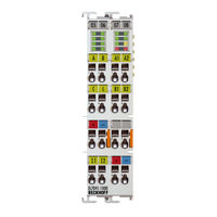
EL7041-1000
Beckhoff EL7041-1000 Manuals
Manuals and User Guides for Beckhoff EL7041-1000. We have
1
Beckhoff EL7041-1000 manual available for free PDF download: Documentation
Beckhoff EL7041-1000 Documentation (255 pages)
EL70 Series Stepper motor terminals
Brand:
Beckhoff
| Category:
Touch terminals
| Size: 8 MB
Table of Contents
Table of Contents
3
1 Foreword
7
Product Overview Stepper Motor Terminals
7
Notes on the Documentation
7
Safety Instructions
9
Documentation Issue Status
10
Version Identification of Ethercat Devices
11
Fig. 1 EL5021 el Terminal, Standard IP20 IO Device with Batch Number and Revision ID (Since 2014/01)
12
Fig. 2 EK1100 Ethercat Coupler, Standard IP20 IO Device with Batch Number
13
Fig. 3 CU2016 Switch with Batch Number
13
Fig. 4 EL3202-0020 with Batch Numbers 26131006 and Unique ID-Number 204418
13
Fig. 5 EP1258-00001 IP67 Ethercat Box with Batch Number 22090101 and Unique Serial Number 158102
14
Fig. 6 EP1908-0002 IP67 Ethercat Safety Box with Batch Number 071201FF and Unique Serial Number 00346070
14
Fig. 7 EL2904 IP20 Safety Terminal with Batch Number/Date Code 50110302 and Unique Serial Num- Ber 00331701
14
Fig. 8 ELM3604-0002 Terminal with ID Number (QR Code) 100001051 and Unique Serial Number 44160201
14
Non-Reactive Bus Terminals
15
Fig. 9 EL7031
15
2 Product Overview
16
EL7031 - Introduction
16
EL7031 - Technical Data
18
EL7041 - Introduction
19
Fig. 10 EL7041-0000
19
Fig. 11 EL7041-0001
19
Fig. 12 EL7041-1000
20
EL7041-X00X - Technical Data
22
Technology
23
3 Basics Communication
27
Ethercat Basics
27
Ethercat Cabling - Wire-Bound
27
General Notes for Setting the Watchdog
28
Fig. 13 System Manager Current Calculation
28
Fig. 14 Ethercat Tab -> Advanced Settings -> Behavior -> Watchdog
29
Ethercat State Machine
30
Fig. 15 States of the Ethercat State Machine
31
Coe Interface
32
Fig. 16 "Coe Online " Tab
33
Fig. 17 Startup List in the Twincat System Manager
34
Fig. 18 Offline List
35
Fig. 19 Online List
36
Distributed Clock
37
4 Mounting and Wiring
38
Installation on Mounting Rails
38
Fig. 20 Attaching on Mounting Rail
38
Fig. 21 Disassembling of Terminal
39
Installation Instructions for Enhanced Mechanical Load Capacity
40
Fig. 22 Power Contact on Left Side
40
Connection
41
Connection System
41
Fig. 23 Standard Wiring
41
Fig. 24 Pluggable Wiring
42
Fig. 25 High Density Terminals
42
Wiring
43
Fig. 26 Connecting a Cable on a Terminal Point
43
Shielding
44
Mounting of Passive Terminals
44
Fig. 27 Correct Configuration
44
Installation Position for Operation with or Without Fan
45
Fig. 28 Incorrect Configuration
45
Fig. 29 Recommended Distances of Installation Position for Operating Without Fan
46
Fig. 30 Recommended Distances for Installation Position for Operation with Fan
47
Fig. 31 Other Installation Positions, Example 1
47
Fig. 32 Other Installation Positions, Example 2
48
UL Notice - Compact Motion
49
Leds and Connection
51
Fig. 33 Leds EL7031
51
General Connection Examples
52
Fig. 34 Connection EL7031
52
Fig. 35 Bipolar Motors
53
Fig. 36 Bipolar Control of a Unipolar Motor,Only One Half of each Winding Is Controlled
53
Leds and Connection
54
Fig. 37 EL7041-0000 Leds
54
El7041
54
Fig. 38 EL7041-0000 Connection
56
Fig. 39 EL7041-0001 Leds
58
Fig. 40 EL7041-0001 Connection
60
Fig. 41 EL7041-1000 Leds
62
General Connection Examples
66
5 Commissioning
68
Twincat Quick Start
68
Twincat 2
92
Twincat 3
92
Twincat Development Environment
92
Installation of the Twincat Real-Time Driver
92
Notes Regarding ESI Device Description
98
Twincat ESI Updater
102
Distinction between Online and Offline
102
OFFLINE Configuration Creation
103
ONLINE Configuration Creation
108
Ethercat Subscriber Configuration
116
General Notes - Ethercat Slave Application
126
Integration into the NC Configuration
135
Configuration of the Main Parameters
139
Basic Principles for the Positioning Interface
146
Predefined PDO Assignment
147
Parameter Set
147
Information and Diagnostic Data
149
States of the Internal State Machine
150
Standard Sequence of a Travel Command
150
Start Types
151
Fig. 178 Endless Travel
153
Fig. 179 Additive Positioning
153
Fig. 180 Calibration with Cam
154
Fig. 181 Calibration with Cam and C-Track
154
Modulo - General Description
155
Fig. 182 Effect of the Modulo Tolerance Window - Modulo Target Position 0° in Positive Direction
156
Examples of Two Travel Commands with a Dynamic Change of the Target Position
159
Fig. 183 Scope Recording Without Overrunning the Target Position
159
Fig. 184 Scope Recording with Overrunning of the Final Target Position
160
Process Data
161
Sync Manager (SM)
161
Fig. 185 Process Data Tab SM2, El70Xx (Default)
161
PDO Assignment
162
Fig. 186 Process Data Tab SM3, El70Xx (Default)
162
Predefined PDO Assignment
165
Application Example
166
Fig. 187 Process Data Tab - Predefined PDO Assignment, El70Xx
166
Fig. 188 Selection of the Target Platform
166
Fig. 189 Selecting the MAC Address
167
Fig. 190 Changing the PLC Path
167
Fig. 191 Required Libraries
168
Fig. 192 Global Variables
168
Fig. 193 Local Variables
168
Fig. 194 Program Code
169
Fig. 195 Visualization
170
EL7031 - Object Description and Parameterization
171
Restore Object
171
Configuration Data
171
Command Object
176
Input Data
177
Output Data
178
Information / Diagnostic Data (Channel Specific)
182
Vendor Configuration Data (Device-Specific)
183
Information / Diagnostic Data (Device-Specific)
184
Standard Objects
184
EL7041 - Object Description and Parameterization
195
Restore Object
195
Configuration Data
195
Command Object
200
Input Data
201
Output Data
202
Information / Diagnostic Data (Channel Specific)
205
Vendor Configuration Data (Device-Specific)
206
Information / Diagnostic Data (Device-Specific)
207
Standard Objects
207
EL7041-1000 - Object Description and Parameterisation
219
Restore Object
219
Configuration Data
219
Command Object
221
Input Data
222
Output Data
222
Information / Diagnostic Data (Channel Specific)
223
Vendor Configuration Data (Device-Specific)
224
Information / Diagnostic Data (Device-Specific)
224
Standard Objects
224
6 Diagnosis - Diag Messages
233
Definition
233
Fig. 196 Diagmessages in the Coe
233
Twincat System Manager Implementation
234
Interpretation
234
Fig. 197 Implementation of the Diagmessage System in the Twincat System Manager
234
7 Appendix
237
Ethercat al Status Codes
237
Firmware Compatibility
237
Firmware Update El/Es/Em/Epxxxx
239
Fig. 198 Device Identifier Consisting of Name EL3204-0000 and Revision -0016
240
Fig. 199 Scan the Subordinate Field by Right-Clicking on the Ethercat Device in Config/Freerun Mode . 240 Fig. 200 Configuration Is Identical
241
Fig. 201 Change Dialog
241
Fig. 202 EEPROM Update
242
Fig. 203 Selecting the New ESI
242
Fig. 204 Display of EL3204 Firmware Version
243
Fig. 205 Firmware Update
244
Fig. 206 FPGA Firmware Version Definition
245
Fig. 207 Context Menu Properties
245
Fig. 208 Dialog Advanced Settings
246
Fig. 209 Select Dialog Advanced Settings
247
Fig. 210 Select Dialog Write FPGA
247
Fig. 211 Select File
248
Fig. 212 Multiple Selection and Firmware Update
248
Restoring the Delivery State
249
Fig. 213 Selecting the "Restore Default Parameters" PDO
249
Fig. 214 Entering a Restore Value in the Set Value Dialog
249
Support and Service
250
List of Illustrations
251
Advertisement
Advertisement
Related Products
Beckhoff EL7041-0000
Beckhoff EL7041-0001
Beckhoff EL7031
Beckhoff EL7211-0000
Beckhoff EL7211-0001
Beckhoff EL72 1-901 Series
Beckhoff EL7211-9014
Beckhoff EL7211-9015
Beckhoff EL7221-9014
Beckhoff EL7221-9015
Beckhoff Categories
Touch terminals
Industrial PC
Control Unit
Industrial Equipment
Power Supply
More Beckhoff Manuals
Login
Sign In
OR
Sign in with Facebook
Sign in with Google
Upload manual
Upload from disk
Upload from URL