Table of Contents
Advertisement
Quick Links
Advertisement
Table of Contents

Related Manuals for Winmate W07IB3S-POM1


Summary of Contents for Winmate W07IB3S-POM1
- Page 1 7~21.5” Intel® Celeron® Bay Trail-M N2930 1.83 GHz User Manual V1.1 For more information on this and other Winmate products, please visit our website at: www.winmate.com Please read this instructions before operating the device and retain them for future reference.
-
Page 2: Table Of Contents
User Manual Contents CONTENTS PREFACE ......................- 4 - ABOUT THIS USER MANUAL ................- 9 - CHAPTER 1: INTRODUCTION ................- 11 - 1.1 Product Features ................... - 11 - 1.2 Package Contents ..................- 12 - 1.3 Product Overview ................... - 13 - CHAPTER 2: MOUNTING ................... - Page 3 User Manual Contents 5.3 Installing Intel Sideband Fabric Device (Intel MBI) Driver (Windows 8) ..- 59 - 5.4 Installing Intel Trusted Engine Interface (TXE) Driver ........- 60 - 5.5 Installing Intel Network Connections .............. - 61 - 5.6 Installing Audio Driver ..................- 62 - CHAPTER 7: TECHNICAL SUPPORT ...............
-
Page 4: Preface
User Manual Preface PREFACE Copyright Notice No part of this document may be reproduced, copied, translated, or transmitted in any form or by any means, electronic or mechanical, for any purpose, without the prior written permission of the original manufacturer. Trademark Acknowledgement Brand and product names are trademarks or registered trademarks of their respective owners. - Page 5 User Manual Preface Warranty Our warranty guarantees that each of its products will be free from material and workmanship defects for a period of one year from the invoice date. If the customer discovers a defect, we will, at his/her option, repair or replace the defective product at no charge to the customer, provide it is returned during the warranty period of one year, with transportation charges prepaid.
- Page 6 User Manual Preface Advisory Conventions Four types of advisories are used throughout the user manual to provide helpful information or to alert you to the potential for hardware damage or personal injury. These are Notes, Important, Cautions, and Warnings. The following is an example of each type of advisory. NOTE: A note is used to emphasize helpful information IMPORTANT:...
-
Page 7: Safety Information
User Manual Preface Safety Information WARNING! / AVERTISSEMENT! Always completely disconnect the power cord from your chassis whenever you work with the hardware. Do not make connections while the power is on. Sensitive electronic components can be damaged by sudden power surges. Only experienced electronics personnel should open the PC chassis. -
Page 8: Safety Precautions
User Manual Preface Safety Precautions For your safety carefully read all the safety instructions before using the device. Keep this user manual for future reference. Always disconnect this equipment from any AC outlet before cleaning. Do not use liquid or spray detergents for cleaning. Use a damp cloth. ... -
Page 9: About This User Manual
User Manual About This User Manual ABOUT THIS USER MANUAL This User Manual provides information about using the Winmate®7~21.5” P-Cap Open Frame Panel PC. The documentation set provides information for specific user needs, and includes: 7~21.5” P-Cap Open Frame Panel PC User Manual – contains detailed description on how to use the panel PC, its components and features. -
Page 10: Chapter 1: Introduction
User Manual Chapter 1 Introduction INTRODUCTION This chapter gives you product overview, describes features and hardware specification. You will find all accessories that come with the Panel PC in the packing list. Mechanical dimensions and drawings included in this chapter. - 10 -... -
Page 11: Product Features
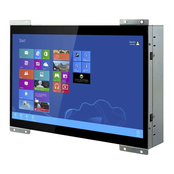
PC in an open-frame housing designed for rear and VESA mounting with integrated bracket design for KIOSK applications. The Winmate P-Cap Open Frame Panel PC is a microprocessor-controlled computer that runs on Intel® Celeron® Bay Trail-M N2930 processor and has 7”, 10.1”, 15” and 21.5”... -
Page 12: Package Contents
Varies by country Varies by product *Notice: Screw bolts provided by Winmate only to be used to screw the panel PC onto a console from the rear side. If you prefer your own bolts, please make sure to use M4 and... -
Page 13: Product Overview
This section describes physical appearance of the Open Frame Panel PC. Notice that input and output connectors vary by product size and specifications. The picture above shows only a prototype model for information purposes only. W07IB3S-POM1 Unit: mm Dimensions: 198.3 x 116.1 x 42.7 №... - Page 14 User Manual Chapter 1 Introduction W10IB3S-POA1 Unit: mm Dimensions:279.28 x 168 x 41.1 № № Description Description ① ④ RJ-45 (LAN) x 2 RS-232/422/485 ② ⑤ HDMI 12V DC IN Power Jack ③ USB 2.0 x 1, USB 3.0 x 1 - 14 -...
- Page 15 User Manual Chapter 1 Introduction R15IB3S-POC3 Unit: mm Dimensions:382 x 274.5 x 53.2 № № Description Description ① ④ RJ-45 (LAN) x 2 RS-232/422/485 ② ⑤ HDMI 12V DC IN Power Jack ③ USB 2.0 x 1, USB 3.0 x 1 - 15 -...
- Page 16 User Manual Chapter 1 Introduction W22IB3S-POA3 Unit: mm Dimensions:552 x 312.72 x 52.8 № № Description Description ① ④ RJ-45 (LAN) x 2 RS-232/422/485 ② ⑤ HDMI 12V DC IN Power Jack ③ USB 2.0 x 1, USB 3.0 x 1 - 16 -...
-
Page 17: Chapter 2: Mounting
User Manual Chapter 2 Mounting MOUNTING This chapter provides step-by-step mounting guide for all available mounting options. - 17 -... -
Page 18: Wall Mount
User Manual Chapter 2 Mounting CHAPTER 2: MOUNTING This chapter provides mounting guide for all available mounting options. Pay attention to cautions and warning to avoid any damages. WARNING! / AVERTISSEMENT! Follow mounting instructions and use recommended mounting hardware to avoid the risk of injury. - Page 19 User Manual Chapter 2 Mounting ❶ ❷ ❸ ❹ - 19 -...
-
Page 20: Chapter 3: Installation
User Manual Chapter 3 Installation INSTALLATION This chapter provides hardware installation instructions and mounting guide for all available mounting options. Pay attention to cautions and warning to avoid any damages. - 20 -... -
Page 21: Cable Mounting Considerations
User Manual Chapter 3 Installation CHAPTER 3: INSTALLATION This chapter provides hardware installation instructions and mounting guide for all available mounting options. Pay attention to cautions and warning to avoid any damages. 3.1 Cable Mounting Considerations For a nice look and safe installation, make sure cables are neatly hidden behind the device. -
Page 22: Wiring Requirements
User Manual Chapter 3 Installation 3.2 Wiring Requirements The following common safety precautions should be observed before installing any electronic device: Strive to use separate, non-intersecting paths to route power and networking wires. If power wiring and device wiring paths must cross make sure the wires are perpendicular at the intersection point. -
Page 23: Connecting Power
User Manual Chapter 3 Installation 3.3 Connecting Power This section provides information on how to use connectors on the P-Cap Open Frame Panel PC. Notice that connectors are located on the top rear side of the device. Be cautious while working with these modules. Please carefully read the content of this chapter in order to avoid any damages. -
Page 24: Connecting To Other Devices
User Manual Chapter 3 Installation 3.4 Connecting to Other Devices This section explains how to connect external interfaces to the Panel PC. 3.4.1 Power Input Connector DC power source input is a power jack connector. Power Input is 12V DC in. Pin №... -
Page 25: Usb 2.0 & Usb 3.0 Connector
User Manual Chapter 3 Installation 3.4.3 USB 2.0 & USB 3.0 Connector Use USB 2.0 or USB 3.0connector to connect your panel PC to other USB 2.0/ USB3.0 compatible devices. Pin № Pin № Name Name USB_D- USB_D+ STDA_SSRX- STDA_SSRX+ GND_DRAIN STDA_SSTX- STDA_SSTX+... -
Page 26: Configuring Serial Port Settings
User Manual Chapter 3 Installation 3.5 Configuring Serial Port Settings Serial port COM1 can be configured for RS-232, RS-422 or RS-485.Jumpers are located on the motherboard. You need to open the housing in order to access the jumpers. CAUTION/ ATTENTION It is recommended to use factory jumper settings. -
Page 27: Chapter 4: Operating The Device
User Manual Chapter 4 Operating the Device OPERATING THE DEVICE This chapter provides detailed information on how to operate the Panel PC. - 27 -... -
Page 28: Operating System
User Manual Chapter 4 Operating the Device CHAPTER 4: OPERATING THE DEVICE In this chapter you will find instructions on how to operate the Panel PC. 4.1 Operating System P-Cap Open Frame Panel PC supports several versions of Windows OS: Windows 10 IoT, , Windows Embedded 8 Standard, Windows 7 Pro for Embedded Systems, and Windows Embedded Standard 7–... -
Page 29: How To Enable Watchdog
Operating the Device 4.2 How to Enable Watchdog To enable Watchdog, you need to download Winmate Watchdog utility. Find more information on Watchdog in “Watchdog Guide” that you can download from Winmate Download Center. Refer to the User Manual for more details. - Page 30 User Manual Chapter 4 Operating the Device Example: Every 10 min watchdog will monitor the system, in case any error occurs the system will restart automatically when the countdown time reaches 0. Every 9 min watchdog timer will be reset to 10 min.
-
Page 31: Using Recovery Wizard To Restore Computer
User Manual Chapter 4 Operating the Device 4.3 Using Recovery Wizard to Restore Computer NOTE: Before starting the recovery process, make sure to backup all user data. The data will be lost after the recovery process. To enable quick one-key recovery procedure: 1. -
Page 32: Chapter 5: Uefi Bios Setup
User Manual Chapter 5 UEFI BIOS Setup UEFI BIOS SETUP BIOS Setup Utility is a program for configuration basic Input / Output system settings of the computer for optimum use. This chapter provides information on how to use BIOS setup, its functions and menu.. -
Page 33: How And When To Use Bios Setup
User Manual Chapter 5 UEFI BIOS Setup CHAPTER 5: UEFI BIOS SETUP BIOS Setup Utility is a program for configuration basic Input / Output system settings of the computer for optimum use. This chapter provides information on how to use BIOS setup, its functions and menu. - Page 34 User Manual Chapter 5 UEFI BIOS Setup The following Keys can be used after entering the BIOS Setup. Function General Help Previous Values Optimized Defaults Save & Exit Exit Change Opt. Enter Select or execute command Cursor ↑ Moves to the previous item Cursor ↓...
-
Page 35: Bios Functions
User Manual Chapter 5 UEFI BIOS Setup 5.2 BIOS Functions 5.2.1 Main Menu The Main menu displays the basic information about yoursystem including BIOS version, processor RC version, system language, time, and date. When you enter BIOS setup, the first menu that appears on the screen is the main menu.It contains the system information including BIOS version, processor RC version, system language, time, and date. -
Page 36: Advanced Settings
User Manual Chapter 5 UEFI BIOS Setup 5.2.2 Advanced Settings Select the Advanced Tab from the setup menu to enter the advanced BIOS setup screen. You can select any of the items on the left frame of the screen to go to the sub menu for the item, such as CPU Configuration. - Page 37 User Manual Chapter 5 UEFI BIOS Setup 5.2.2.1 Super I/O Configuration Serial Port 1 Configuration Serial Port This item enables or disables Serial Port (COM). Options: Enabled (Default) / Disabled Change Settings This item allows you to select an optimal setting for Super IO device. Options: Auto (Default) / IO=3F8h;...
- Page 38 User Manual Chapter 5 UEFI BIOS Setup 5.2.2.2 Hardware Monitor - 38 -...
- Page 39 User Manual Chapter 5 UEFI BIOS Setup 5.2.2.3 CPU Configuration Active Processor Cores This item sets number of cores to enable in each processor package Options: All (Default) / 1 Limit CPUID Maximum When the computer is booted up, the operating system executes the CPUID instruction to identify the processor and its capabilities.
- Page 40 User Manual Chapter 5 UEFI BIOS Setup Adjacent Cache Line Prefetch The processor has a hardware adjacent cache line prefetch mechanism that automatically fetches an extra 64-byte cache line whenever the processor requests for a 64-byte cache line. This reduces cache latency by making the next cache line immediately available if the processor requires it as well.
- Page 41 User Manual Chapter 5 UEFI BIOS Setup 5.2.2.4 PPM Configuration EIST This item enables or disables Intel SpeedSteps. Options: Enabled (Default) / Disabled CPU C state Report This item enables or disables CPU C state report to OS. Options: Enabled (Default) / Disabled Enhanced C state This item enables or disables Enhanced CPU C state Options: Enabled (Default) / Disabled...
- Page 42 User Manual Chapter 5 UEFI BIOS Setup 5.2.2.5 SATA Configuration Serial-ATA (SATA) This item enables/disables Serial ATA Device. Options: Enabled (Default) / Disabled SATA ODD Port This item selects SATA ODD Port Options: No ODD (Default) / Port0 ODD / Port1 ODD SATA Mode This item determines how SATA controller(s) operate.
- Page 43 User Manual Chapter 5 UEFI BIOS Setup 5.2.2.6 Network Stack Configuration Network Stack This item enables or disables UEFI network stack Options: Disabled (Default) / Enabled Note: The following items appear only when you set the Network Stack function to [Enabled] IPv4 PXE Support This item enables or disables IPv4 PXE Boot Support.
- Page 44 User Manual Chapter 5 UEFI BIOS Setup 5.2.2.7 CSM Configuration CSM Support This item enables or disables CSM Support Options: Disabled (Default) / Enabled Note: The following items appear only when you set the CSM Support to [Enabled] GateA20 Active Upon Request –...
- Page 45 User Manual Chapter 5 UEFI BIOS Setup Network This option controls the execution of UEFI and Legacy PXE OpROM Options: Legacy only (Default) / Do not launch / UEFI only / Legacy first / UEFI first Storage This option controls the execution of UEFI and Legacy Storage OpROM Options: Legacy only (Default) / Do not launch / UEFI only / Legacy first / UEFI first Video This option controls the execution of UEFI and Legacy Video OpROM...
- Page 46 User Manual Chapter 5 UEFI BIOS Setup Legacy USB Support This item determines if the BIOS should provide legacy support for USB devices like the keyboard, mouse, and USB drive. This is a useful feature when using such USB devices with operating systems that do not natively support USB (e.g.
-
Page 47: Chipset Menu
User Manual Chapter 5 UEFI BIOS Setup 5.2.3 Chipset Menu This section describes configuring the PCI bus system. PCI, or Personal Computer Interconnect, is a system which allows I/O devices to operate at speeds nearing the speed of the CPU itself uses when communicating with its own special components. - 47 -... - Page 48 User Manual Chapter 5 UEFI BIOS Setup 5.2.3.1 North Bridge Intel IGD Configuration Integrated Graphics Device Enable: Enable Integrated Graphics Device (IGD) when selected as the Primary Video Apaptor. Disable: Always disable IGD. Options: Enabled (Default) / Disabled IGD Turbo Enable Enable: Enable IGD Turbo Enable.
- Page 49 User Manual Chapter 5 UEFI BIOS Setup Options: 2MB (Default) / 1MB VCC_Vnn Config for Power state2 This item enables or disables Vcc Vnn Config for power state2 Options: Disabled (Default) / Enabled RC6 (Render Standby) This item enables or disables render standby support. Options: Enabled (Default) / Disabled LCD Control Boot Display Device...
- Page 50 User Manual Chapter 5 UEFI BIOS Setup Azalia HD Audio Azalia Controller This item controls detection of the Azalia device. Disabled = Azalia will be unconditionally disabled. Enabled = Azalia will be unconditionally Enabled. Auto = Azalia will be enabled if present, disabled otherwise. Options: Enabled (Default) / Disabled Azalia HDMI Codec This item enables or disables internal HDMI codec for Azalia.
-
Page 51: Security Menu
User Manual Chapter 5 UEFI BIOS Setup Options: Enabled (Default) / Disabled Onboard LAN Ootion ROM This item enables or disables the Boot Option for Legacy Network Devices. Options: Disabled (Default) / Enabled High Precision Timer This item enables or disables the High Precision Event Timer. Options: Enabled (Default) / Disabled 5.2.4 Security Menu This section allows to configure and improve system, and set up some system features... - Page 52 User Manual Chapter 5 UEFI BIOS Setup Key Management Enroll All Factory Default Keys It allows you to immediately load/clear the default Security Boot keys, Platform key (PK), Key-exchange Key (KEK), Signature database (db), and Revoked Signatures (dbx). The Platform Key (PK) state will change from Unloaded mode to Loaded mode. The settings are applied after reboot or at the next reboot.
- Page 53 User Manual Chapter 5 UEFI BIOS Setup 5.2.5 Boot Menu Setup Prompt Timeout This item sets number of seconds to wait for setup activation key. Options: 2 (Default) Bootup NumLock State This item selects the keyboard NumLock state. Options: On (Default) / Off Full Screen Logo Display This item allows you to enable/disable Full Screen Logo Show function.
- Page 54 User Manual Chapter 5 UEFI BIOS Setup 5.2.6 Exit Menu This menu allows you to load the optimal default settings, and save or discard the changes to the BIOS items. Discard Changes and Exit Abandon all changes made during the current session and exit setup. Save Changes and Reset Reset the system after saving the changes.
-
Page 55: Chapter 6: Driver Installation
User Manual Chapter 6 Driver Installation DRIVER INSTALLATION This chapter describes how to install all necessary drivers. - 55 -... -
Page 56: Installing Chipset Driver
User Manual Chapter 6 Driver Installation CHAPTER 6: DRIVER INSTALLATION This chapter describes how to install all necessary drivers. 6.1 Installing Chipset Driver Step 1 Insert the CD that comes with the motherboard. Open the file document “Chipset Driver” and click “infinst_auto.exe” to install driver. Step 2 Click Next to continue. - Page 57 User Manual Chapter 6 Driver Installation Step 3 Click Yes to agree the license terms. Step 4 Click Next to install the driver. Step 5 Software setup progress window will appear, click Next to continue. Step 6 Click “Yes, I want to restart this computer now” to finish the installation. - 57 -...
-
Page 58: Installing Graphics Driver
User Manual Chapter 6 Driver Installation 5.2 Installing Graphics Driver Step 1 Insert the CD that comes with the motherboard. Open the file document “Graphics Driver” and click Setup to execute the setup. Step 2 Setup Welcome Window will appear, click Next to continue the process. Step 3 Carefully read the license terms and click Yes to agree. -
Page 59: Installing Intel Sideband Fabric Device (Intel Mbi) Driver (Windows 8)
User Manual Chapter 6 Driver Installation 5.3 Installing Intel Sideband Fabric Device (Intel MBI) Driver (Windows 8) Step 1 Insert the CD that comes with the motherboard. Open the file document “MBI” and click “Setup.exe” to install the driver. Step 2 Welcome to the setup program window will appear, click Next to start the installation. -
Page 60: Installing Intel Trusted Engine Interface (Txe) Driver
User Manual Chapter 6 Driver Installation 5.4 Installing Intel Trusted Engine Interface (TXE) Driver Step 1 Insert the CD that comes with the motherboard. Open the file document “TXE” and click “Setup TXE.exe” to install the driver. Step 2 Welcome to the setup program window will appear, click Next to start the installation. -
Page 61: Installing Intel Network Connections
User Manual Chapter 6 Driver Installation 5.5 Installing Intel Network Connections User must confirm the type of operating system is being used before installing Intel Network Connections. Follow the steps below to complete the installation. Step 1 Click “PROWin64.exe” Step 2 Click Yes to start the installation. Step 3 Welcome window will appear, click Next to install the driver. -
Page 62: Installing Audio Driver
User Manual Chapter 6 Driver Installation 5.6 Installing Audio Driver The ALC886 series are high-performance 7.1+2 channel high definition audio codecs that provide ten DAC channels for simultaneous support of 7.1 sound playback, plus 2 channels of independent stereo sound output (multiple streaming) through the front panel stereo outputs. -
Page 63: Chapter 7: Technical Support
User Manual Chapter 7 Technical Support TECHNICAL SUPPORT This chapter includes pathway to technical support. - 63 -... -
Page 64: Introduction
This chapter includes technical support documents and software developing kit (SDK). If any problem occurs fill in problem report form enclosed and immediately contact us. 6.1 Introduction Winmate provides the following SDK and Utilities for Open Frame Panel PC with Intel® Celeron® N2930: Item File Type Description... -
Page 65: Problem Report Form
User Manual Chapter 7 Technical Support 6.2 Problem Report Form P-Cap Open Frame Panel PC Customer name: Company: Tel.: Fax: E-mail: Date: Product Serial Number: _____________________________________________________ Problem Description: Please describe the problem as clearly as possible. Detailed description of the occurred problem will allow us to find the best solution to solve the problem as soon as possible. -
Page 66: Appendix A: Product Specifications
User Manual Appendix A Product Specifications PRODUCT SPECIFICATIONS This section includes product specifications. Appendix - 66 -... - Page 67 User Manual Appendix A Product Specifications APPENDIX A: PRODUCT SPECIFICATIONS Hardware Specifications Model Name W07IB3S-POM1 W10IB3S-POA1 R15IB3S-POC3 W22IB3S-POA3 Display 7" Size 10.1" 15.6" 21.5" Resolution 1024 x 600 1920 x 1200 1024 x 768 1920 x 1080 Brightness (typ.) (typ.) (typ.)
- Page 68 Winmate Inc. 9F, No.111-6, Shing-De Rd., San-Chung District, New Taipei City 24158, Taiwan, R.O.C Tel: 886-2-8511-0288 Fax: 886-2-8511-0211 Email: sales@winmate.com.tw Official website: www.winmate.com...
Need help?
Do you have a question about the W07IB3S-POM1 and is the answer not in the manual?
Questions and answers