Table of Contents
Advertisement
Quick Links
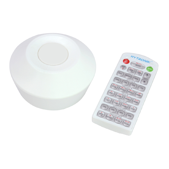
SURFACE MOUNT HIGH BAY MOTION SENSOR HMW12
1. Technical Specifications
Product type
High bay microwave motion sensor (Daylight harvest)
Operating voltage
120~277VAC 50/60Hz
Rated load
Resistive:700W@120V; 1600W@220-277V;
Capacitive:400VA@120V; 800VA@220-277V;
Power consumption
< 1W
o
Detection angle
360
Detection area (DxH)
12 x 12m (Maximum)
Mounting height
15M(Maximum)
Detection range
10% / 50% / 75% / 100%
Hold time
2s / 30s / 1min / 5min / 10min / 15min / 20min / 30min
Stand-by time
0s / 10s / 1min / 5min / 10min / 30min / 1h / +
Stand-by dimming level
10% / 20% / 30% / 50%
Daylight threshold
50 ~ 500Lux, Disable
Warmming up time
20s
o
Operating temperature
-20
C ~ +50
IP rating
IP42
3. Rotary Switch Settings
A rotary switch is built inside the sensor for
scene selection / fast programming. Total
16 channels available:
Detection
Hold
Channel
range
time
0
100%
5s
1
100%
1min
2
100%
5min
3
100%
5min
4
100%
5min
5
100%
5min
6
100%
10min
7
100%
10min
8
100%
10min
9
100%
10min
A
100%
20min
B
100%
20min
C
100%
30min
D
100%
30min
E
100%
30min
F
100%
5s
Note: settings can also be changed by remote control HRC-11. The last action controls.
4. Functions
4.1 Daylight Harvest (Daylight Regulating)
Daylight sensor measures the available surrounding natural light, calculates how much electrical light is
needed to reach the total lux expected. The demand is given to the LED driver by 1-10V signal, so as to
deliver the needed amount of electric light.
Light level
Energy Saving Zone
0
Installation and Instruction Manual
o
C
Rotary switch preset (Please
see the location in 2. Installation)
Stand-by
Stand-by
Daylight
time
dimming level
threshold
10s
10%
5min
10%
10min
10%
+∞
10%
+∞
10%
+∞
30%
30min
10%
+∞
10%
+∞
10%
+∞
30%
1h
10%
+∞
30%
+∞
10%
+∞
30%
+∞
50%
10s
10%
Hold time
Normal Electric Light
Daylight controlled light
Stand-by time
Natural light
24
Time (hrs)
2. Installation
Warnings:
1. Installation must be carried out by a
qualified engineer in accordance with
local regulations.
2. Disconnect supply before installing.
3. Install to a solid surface - vibrations may
cause mis-triggering.
4. Ensure environmental conditions are
suitable for electronic equipment
Direct junction "J" box mounting
a. Separate control board (A) from facia (B)
& Surface box (C). C is not required.
b. Make electrical connections to control board
(A). See detailed wiring diagram on next page.
c. Secure control board (A) to junction box.
d. Set-up sensor modes as per sections 3 & 4
of this manual.
e. Clip facial plate (B) to control board (A).
Disable
50Lux
50Lux
75Lux
100Lux
4.2 Lux Off Function
200Lux
The light dims to minimum level even switches off completelly if ambient daylight is
50Lux
sufficient (natural light level exceeds target lux level), no matter it is during hold-time or
stand-by time, with or without motion.
75Lux
Note: if the stand-by time is preset at "+∞", the light never turns off even when natural light
100Lux
is sufficient.
200Lux
100Lux
200Lux
4.3 Manual Override
100Lux
With the help of push-switch, this sensor maybe over-ridden by the end-users to switch on/off
200Lux
the lights manually, or adjust the light brightness during motion hold-time. This makes the
400Lux
product more user-friendly and offers more options to fit for extra-ordinary demands.
100Lux
* Short push (<1s): on/off function;
ON → OFF: the light turns off immediately and cannot be lighten for a certain time (equals to
hold time preset) even there is movement is detected. After this period, the sensor goes back
to auto sensor mode.
OFF → ON: the light turns on 100% and goes to auto sensor mode, even when ambient
Lux level exceeds the daylight threshold.
* Long push (>1s): adjust the target lux level by turning the light up or down. Both the
4.4 Semi-auto Function (Absence Detection)
The motion sensor is employed, but only activated on the manual press of the push switch,
The light remains on during presence and dims down in absence, eventually switching off
automatically after the stand-by time has expired.
Note: in this mode, the push terminal used for the 'manual on' switch input.
End-user can choose either function 4.3 or 4.4 for application. Default function is 4.3.
C - Surface box
B - Facia Cover
Infrared receiver
HF Sensor module
Rotary switch preset
Surface mount assembly
a. Separate control board (A) from facia (B) &
Surface box (C).
b. Securely mount surface box (C) to a flat and
solid surface.
c. Make electrical connections to control board
(A). See detailed wiring diagram on next page.
d. Set-up sensor modes as per sections 3 & 4 of
this manual.
e. Secure control board (A) to surface box (C).
f. Clip facial plate (B) to control board (A).
adjustment on remote control and push switch can overwrite each other,
the last adjustment remains in memory.
Photocell
LED indicator
A - Control Board
HMW12-20170309-A1
Advertisement
Table of Contents

Subscribe to Our Youtube Channel
Related Manuals for Hytronik HMW12


Summary of Contents for Hytronik HMW12
- Page 1 SURFACE MOUNT HIGH BAY MOTION SENSOR HMW12 Installation and Instruction Manual 1. Technical Specifications 2. Installation Product type High bay microwave motion sensor (Daylight harvest) Warnings: C - Surface box Operating voltage 120~277VAC 50/60Hz 1. Installation must be carried out by a...
-
Page 2: Wiring Diagram
The fixture is on when it should not Adjust zone, change installation site expelled from fans, open windows Hytronik Industrial Ltd. | www.hytronik.com 3rd Floor, block C, complex building, 155#, Bai'gang road south, Bai'gang village, Xiao Jin Kou town, Huicheng district, Huizhou 516023...
Need help?
Do you have a question about the HMW12 and is the answer not in the manual?
Questions and answers