Sign In
Upload
Manuals
Brands
SICK Manuals
Barcode Reader
CLV621
User Manuals: SICK CLV621 Barcode Scanner
Manuals and User Guides for SICK CLV621 Barcode Scanner. We have
2
SICK CLV621 Barcode Scanner manuals available for free PDF download: Operating Instructions Manual
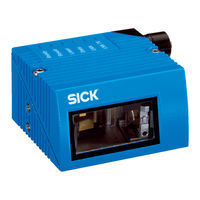
SICK CLV621 Operating Instructions Manual (106 pages)
CLV62 Series
Brand:
SICK
| Category:
Barcode Reader
| Size: 4 MB
Table of Contents
Software Versions
2
Table of Contents
3
Abbreviations
5
Figures and Tables
5
Tables
6
Figures
7
1 Notes on this Document
9
Purpose
9
Target Group
9
Depth of Information
9
Tab. 1-1: Target Group
9
Used Symbols
10
2 Safety Information
11
Authorised Users
11
Tab. 2-1: Required Qualification for Starting up the Bar Code Scanner
11
Intended Use
12
General Safety Precautions and Protection Measures
12
Fig. 2-1: Outlet Opening of the Laser Radiation at the Reading Window (Shown Here: Ethernet Version)
13
Tab. 2-2: Laser Data of Clv62X
14
Fig. 2-2: Laser Warning Sign Attached to the Bar Code Scanner at Delivery
14
Quick Stop and Quick Restart
15
Environmental Information
16
3 Quick-Start
17
Preparing the Bar Code Scanner for the Quick Start
17
Establishing Connection with the Bar Code Scanner
18
Performing the Reading
18
Fig. 3-1: Register Tab Quickstart
18
4 Product Description
21
Setting up the Bar Code Scanner
21
Fig. 4-1: Housing Types of the Clv62X Bar Code Scanner
21
Fig. 4-2: Device View of the Clv62X Bar Code Scanner (Shown Here: Ethernet-Version)
22
Included in Delivery
23
Tab. 4-1: Clv62X Bar Code Scanner Delivery
23
Device Versions
24
Tab. 4-2: Variants of the Clv62X Bar Code Scanner
24
System Requirements
25
Product Features and Functions (Overview)
25
Bar Code Scanner Methods of Operation
26
Tab. 4-3: Overview of the Bar Code Scanner's Product Features and Functions
26
Fig. 4-3: Bar Code Scanner's Methods of Operation in a Conveyor System (Schematic)
27
Fig. 4-4: Reading Operation Mode for the Clv62X Bar Code Scanner in Stand-Alone Operation
29
Tab. 4-4: Data Interface Function
30
Indicators and Control Elements
31
Of the Bar Code Scanner
31
Tab. 4-5: LED Indications
32
5 Installation
33
Overview of Installation Sequences
33
Installation Preparations
33
Fig. 5-1: Example: Fixing the Bar Code Scanner with the Angle with Adapter Plate No. 2042902
34
Installation Location
35
Fig. 5-2: Exchanging the Laser Warning Sign
35
Fig. 5-3: Allocation of the Scanning Line(S) for the Bar Code and Conveyor System
36
Fig. 5-4: Definition of the Reading Distance a and the Aperture Angle Α
36
Tab. 5-1: Permitted Reading Angles between the Scanning Line and Bar Code
37
Fig. 5-5: Line Scanner: Reading Angles that Occurs between the Scanning Line and Bar Code
37
Fig. 5-6: Avoiding Surface Reflection Using the Line Scanner as an Example: Angle between Emitting Light and Bar Code (Tilted Away from the Plumb Line)
37
Fig. 5-7: Counting Direction of the Bar Code Along the Scanning Line
38
Installation of the Bar Code Scanner
39
Of the Bar Code Scanner
39
Installing External Components
40
Fig. 5-8: Line Scanner: Installation Example for Positioning the External Reading Pulse Sensor
40
Removing the Bar Code Scanner
41
6 Electrical Installation
43
Overview of Installation Sequence
43
Electrical Installation Preparation
43
Electrical Connections and Cables
44
Fig. 6-1: Standard Version: Electrical Connections at the Bar Code Scanner with Connection Cable
44
Fig. 6-2: Ethernet Version: Electrical Connections at the Bar Code Scanner with Connector Unit
44
Tab. 6-1: Electrical Connections to the Bar Code Scanner with a Fixed Cable and Connector (Standard Version)
45
Tab. 6-2: Electrical Connections to the Bar Code Scanner with Connector Unit
45
Tab. 6-3: Standard Version: Pin Assignment of the 15-Pole D-Sub-HD Cable Connector
46
Tab. 6-4: Ethernet Version: Pin Assignment of the 4-Pole M12 Socket
46
Tab. 6-5: Ethernet Version: Pin Assignment on the 12-Pole M12 Plug
47
Performing Electrical Installation
48
Fig. 6-3: Direction of Rotation of the Connector Unit
48
(Ethernet Version)
49
Tab. 6-6: Recommended Maximum Cable Lengths, Depending on the Selected
49
Fig. 6-4: Wiring the Serial Host Data Interfaces (RS-232 or RS-422) on the 15-Pole D-Sub-HD Plug
49
Fig. 6-5: Function of the Ethernet Interface
50
Fig. 6-6: Wiring the "Sensor 1" Switching Input on the 15-Pole D-Sub-HD Plug
51
Tab. 6-7: Ratings for the Switching Inputs
52
Fig. 6-7: Wiring the "Sensor 2" Switching Input on the 15-Pole D-Sub-HD Plug
52
Tab. 6-8: Ratings for the Switching Outputs
53
Fig. 6-8: Possible Wiring of the "Result 1" Switching Output on the 15-Pole D-Sub-HD Plug
53
Pin Assignment and Wire Colour Assignment of the Assembled Cables
54
Tab. 6-9: Pin Assignment of the 4-Pole M12 Plug and the 6-Pole RJ45 Plug
54
Tab. 6-10: Pin Assignment of the 12-Pole M12 Socket and the 15-Pole
54
Tab. 6-11: Pin Assignment of the 12-Pole M12 Socket and Wire Colours at the Open End
55
Tab. 6-12: Pin Assignment of the 5-Pole M12 Plug and Wire Colours at the Open End
55
Tab. 6-13: Pin Assignment of the 15-Pole D-Sub-HD Socket and Wire Colours at the Open Cable End
56
7 Startup and Configuration
57
Overview of the Startup Procedure
57
SOPAS-ET Configuration Software
57
Establish Communication with the Bar Code Scanner
58
Tab. 7-1: Default Setting for the SOPAS-ET Configuration Software (Excerpt)
58
Tab. 7-2: Connection between the PC with SOPAS-ET Configuration Software and the Bar Code Scanner
58
First Startup
60
Fig. 7-1: Configuration with SOPAS-ET
60
Default Setting
62
Adjusting the Bar Code Scanner
63
8 Maintenance
65
Maintenance During Operation
65
Cleaning the Bar Code Scanner
65
Cleaning Further Optical Effective Surfaces
67
Fig. 8-1: Cleaning the Reading Window
67
Fig. 8-2: Cleaning of the External Optical Sensors (Reading Pulse Generator)
67
Checking the Incremental Encoder
68
Replacing a Bar Code Scanner
68
9 Troubleshooting
69
Overview of Errors and Malfunctions Which Could Occur
69
Detailed Malfunction Analysis
69
Status Protocol
70
SICK Support
70
10 Technical Data
71
Datasheet of Clv62X Bar Code Scanner
71
Data Transfer Rate
71
Tab. 10-1: Technical Specifications for the Clv62X Bar Code Scanner
72
Specification Diagrams
73
Tab. 10-2: Reading Conditions for All Specification Diagrams
73
Fig. 10-1: Reading Ranges of the CLV620 Bar Code Scanner (with Front Reading Window)
73
Fig. 10-2: Reading Ranges of the CLV620 Bar Code Scanner (with Side Reading Window)
74
Fig. 10-3: CLV620: Set of Characteristic Curves for Scan Frequency, Depending on the Reading Distance and Resolution (Front Reading Window)
74
Fig. 10-4: Reading Ranges of the CLV621 Bar Code Scanner (with Front Reading Window)
75
Fig. 10-5: Reading Ranges of the CLV621 Bar Code Scanner (with Side Reading Window)
75
Fig. 10-6: CLV621: Set of Characteristic Curves for Scan Frequency, Depending on the Reading Distance and Resolution (Front Reading Window)
76
Fig. 10-7: Reading Range of the CLV622 Bar Code Scanner (with Front Reading Window)
77
Fig. 10-8: Reading Range of the CLV622 Bar Code Scanner (with Side Reading Window)
77
Fig. 10-9: CLV622: Set of Characteristic Curves for Scan Frequency, Depending on the Reading Distance and Resolution (Front Reading Window)
78
Clv62X Bar Code Scanner Dimensional Drawings
79
Fig. 10-10: Standard Version: Dimensions of the Bar Code Scanner with Front Reading Window (Clv62X-0000 and Clv62X-1000)
79
Fig. 10-11: Standard Version: Dimensions of the Bar Code Scanner with Side Reading Window (Clv62X-2000 and Clv62X-3000)
80
Fig. 10-12: Ethernet Version: Dimensions of the Bar Code Scanner with Front Reading Window (Clv62X-0120 and Clv62X-1120)
81
Fig. 10-13: Ethernet Version: Dimensions of the Bar Code Scanner with Side Reading Window (Clv62X-2120 and Clv62X-3120)
82
11 Appendix
83
Appendix Overview
83
Configuring the Bar Code Scanner with Command Strings
83
Calculating the Code Length of a Bar Code
84
Tab. 11-1: Help Table for Calculating the Code Length of a Bar Code
84
Ordering Information for Bar Code Scanner and Accessories
85
Tab. 11-2: Variants of the Clv62X Bar Code Scanner
85
Tab. 11-3: in Stock Accessories: Installation Accessories
86
Tab. 11-4: in Stock Accessories: Connection Modules
87
Tab. 11-5: in Stock Accessories: Extensions for Connection Modules
89
Tab. 11-6: in Stock Accessories: Separate Field Bus Modules
89
D-Sub-HD Plug
90
Tab. 11-7: in Stock Accessories: Cables and Connectors for the Standard Version
90
Tab. 11-8: in Stock Accessories: Cables and Connectors for the Ethernet Version
90
Tab. 11-9: in Stock Accessories: General Cables and Connectors for Bar Code Scanner
92
Dimensional Drawing Accessories
93
Fig. 11-1: Dimensions of the Fixing Bracket No. 2020410
93
Fig. 11-2: Dimensions of the Quick Release Clamp No. 2025526
94
Fig. 11-3: Dimensions of the Round Rod Holder No. 2042802
95
Fig. 11-4: Dimensions of the Bracket with Adapter Plate No. 2042902 (here Shown Only the Bracket)
95
Supplementary Documentation
96
Tab. 11-10: Supplementary Documentation
96
Glossary
97
EC Declaration of Conformity
104
Fig. 11-5: EC Declaration of Conformity for the Bar Code Scanner (Page 1, Scaled down Version)
104
Code Samples of Bar Codes (Selection)
105
Fig. 11-6: Code Samples of Bar Codes of Various Module Widths (Print Ratio 2:1)
105
Advertisement
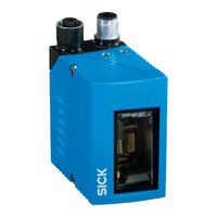
SICK CLV621 Operating Instructions Manual (70 pages)
CLV62x series
Brand:
SICK
| Category:
Barcode Reader
| Size: 6 MB
Table of Contents
Bar Code Scanner
1
Table of Contents
3
1 About this Document
5
Information on the Operating Instructions
5
Scope
5
Explanation of Symbols
5
Further Information
6
Customer Service
6
2 Safety Information
7
Intended Use
7
Incorrect Use
7
IP Technology
7
Limitation of Liability
7
Modifications and Conversions
8
Requirements for Skilled Persons and Operating Personnel
8
Hazard Warnings and Operational Safety
9
Switching off the Device
11
Protection of the Environment
11
Repairs
11
3 Product Description
12
Product ID
12
Product Characteristics
14
4 Transport and Storage
20
Transport
20
Transport Inspection
20
Storage
20
5 Mounting
21
Overview of Mounting Procedure
21
Scope of Delivery
21
Preparation for Mounting
21
Mounting Location
22
Mounting the Device
24
Mounting of External Components
25
6 Electrical Installation
27
Safety
27
Prerequisites for the Safe Operation of the Device in a System
28
Wiring Notes
31
Pin Allocation of the Connections
31
Connection Diagrams
34
Wiring Interfaces
36
7 Commissioning
41
Overview of the Commissioning Steps
41
SOPAS ET Configuration Software
41
Start the SOPAS ET Configuration Software and Connect to the Device
41
Initial Commissioning
42
Adjust the Device
42
Fine Adjustment and Further Configuration
43
8 Operation
45
Operating and Status Indicators
45
Operating Options
45
9 Maintenance
46
Cleaning
46
10 Troubleshooting
49
Overview of Possible Errors and Faults
49
Detailed Fault Analysis
49
Status Log
49
Replacing the Device
50
Customer Service
51
11 Decommissioning
52
Disposal
52
12 Technical Data
53
Optical Lens System
53
Performance
53
Interfaces
54
Mechanics/Electronics
54
Ambient Data
55
Dimensional Drawings
56
Reading Field Diagrams
57
13 Accessories
65
14 Annex
66
Notes on PROFINET
66
EU Declaration of Conformity / Certificates
67
Certification in Accordance with UL60950
67
Dimensional Drawings
68
Abbreviations Used
68
Advertisement
Related Products
SICK CLV62x
SICK CLV620
SICK CLV622
SICK CLV62 Series
SICK CLV61x FIELDBUS Series
SICK CLV60 series
SICK CLV63 Series
SICK CLV631
SICK CLV612
SICK CLV601 E Series
SICK Categories
Accessories
Security Sensors
Measuring Instruments
Scanner
Barcode Reader
More SICK Manuals
Login
Sign In
OR
Sign in with Facebook
Sign in with Google
Upload manual
Upload from disk
Upload from URL