Page 1
REFERENCE GUIDE PMAC Quick Reference Reference Guide for PMAC Products 3A0-PMACQR-xPRx September 29, 2009 USER MANUAL Single Source Machine Control Power // Flexibility // Ease of Use 21314 Lassen Street Chatsworth, CA 91311 // Tel. (818) 998-2095 Fax. (818) 998-7807 // www.deltatau.com...
PMAC Quick Reference Guide Table of Contents INTRODUCTION ...............................1 Description of PMAC..............................1 Types of PMAC ................................2 PMAC PC or PMAC VME Features........................2 PMAC PC ................................2 PMAC Lite ................................2 PMAC VME ................................2 PMAC STD ................................2 PMAC Mini................................3 PMAC2 .................................4 PMAC2 Ultralite..............................4 Turbo PMAC Family ............................4...
Page 6
PMAC Quick Reference Guide Flags Power Supply (Optional) ..........................24 Overtravel Limits and Home Switches........................24 Disabling the Overtravel Limits Flags .......................24 Types of Overtravel Limits..........................24 Home Switches..............................25 PMACPack and PMAC2 Flag Inputs .........................25 Checking the Flag Inputs............................25 Motor Signals Connections .............................26 Incremental Encoder Connection ........................26 Checking the Encoder Inputs..........................26 Checking the DAC Outputs..........................26...
Page 7
PMAC Quick Reference Guide External Time Base Control (Electronic Cams) ....................59 Position Following (Electronic Gearing) ......................59 Cutter Radius Compensation ..........................59 Synchronous M-Variable Assignment.........................60 Synchronizing PMAC to Other PMACs......................60 Axis Transformation Matrices ..........................60 Position-Capture and Position-Compare Functions ..................60 Learning a Motion Program..........................60 PLC PROGRAMS..............................61 Entering a PLC Program ............................62 PLC Program Structure ............................63...
Page 8
PMAC Quick Reference Guide Table of Contents...
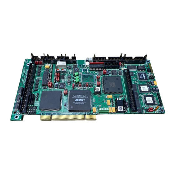
There are five hardware versions of PMAC: the PMAC PC, the PMAC Lite, the PMAC VME, the PMAC STD and the PMAC Mini. These cards differ from each other in their form factor, the nature of the bus interface, and in the availability of certain I/O ports.
PMAC STD With the same features as the PMAC PC, the PMAC STD is the only option for STD based applications. The dual-ported RAM option is not available for the PMAC STD and it is limited to eight channels, no Acc-24 is available for it.
PMAC Quick Reference Guide PMAC Lite PMAC Mini PMAC PC PMAC STD PMAC VME PMAC Pack Turbo PMAC PC Turbo PMAC VME Turbo PMAC2 3U UMAC Turbo System Turbo PMAC2 PC Ultralite Turbo PMAC2 PC PMAC Mini The PMAC Mini is recommended for applications with one or two channel requirements in either a PC based or stand alone environment.
PMAC Quick Reference Guide PMAC2 PMAC2 is available in either PC, PCI, or VME formats. It is suggested for applications that require a digital amplifier control (direct PWM signals) or applications with a combination of analog and digital axis. PMAC2 is recommended also for the use of its built-in features that are optional in PMAC (1): pulse and direction outputs, MLDT inputs, optional 12-bits analog to digital inputs, two extra encoder inputs, improved position compare/capture feature and one channel of parallel feedback.
DISPLAY command, executing in either motion or PLC programs. Control-Panel Port I/O (JPAN Port) The JPAN connector (J2 on PMAC PC, Lite, VME, and top board of PMAC STD) is a 26-pin connector with dedicated control inputs, dedicated indicator outputs, a quadrature encoder input, and an analog input.
PMAC Quick Reference Guide The new yellow LED located beside the red and green LEDs, when lit, indicates that the phase-locked loop that multiplies the CPU clock frequency from the crystal frequency on the Option CPU is operational and stable. This indicator is for diagnostic purposes only; it may not be present on all boards. Working with PMAC When used for the first time, the card must be configured for a specific application, using both hardware and software features, in order to run that application properly.
PMAC Quick Reference Guide Programming PMAC Motion or PLCs programs are entered in any text file and then downloaded with PEWIN to PMAC. PEWIN provides a built-in text editor for this purpose but any other text editor could be used conveniently.
PMAC Quick Reference Guide Single Character I/O Bringing in a single character from, or sending out a single character to, the serial port or host port (PC or STD) is the highest priority in PMAC. This task takes only 200 nsec per character, but having it at this high priority ensures that the host cannot outrun PMAC on a character-by-character basis.
PMAC Quick Reference Guide VME Mailbox Processing Reading or writing a block of up to sixteen characters through the VME mailbox registers is the fourth highest priority in PMAC. The host controls the rate at which this happens. This never takes a significant portion of PMAC’s computational power.
PMAC Quick Reference Guide All enabled PLCC programs execute one scan (to the end or to an ENDWHILE statement) starting from lowest numbered to highest uninterrupted by any other background task (although it can be interrupted by higher priority tasks). At power-on\reset, PLCC programs run after the first PLC program runs. The receipt of a control character from any port is a signal to PMAC that it must respond to a command.
PMAC Quick Reference Guide Most of the housekeeping functions are safety checks such as following error limits and overtravel limits. Since compiled PLCCs are executed at the same rate as the housekeeping functions, code to complement or replace these functions could be placed in a compiled PLCC. If, for example, an extra input flag is wanted for position capturing purposes either the end-of-travel limit inputs or the amplifier fault input could be used.
Page 20
PMAC Quick Reference Guide A faster than 20 MHz PMAC will perform calculations faster, in proportion to the corresponding clock rate increase. In general, a clock rate increase is used to increase the real time interrupt (RTI) share of the total computational time available.
PMAC Quick Reference Guide PMAC EXECUTIVE PROGRAM, PEWIN With PEWIN, PMAC can be configured and controlled. PEWIN is designed as a development tool for creating and managing PMAC implementations. It provides a terminal interface to the PMAC and a text editor for writing and editing PMAC motion programs and PLC programs.
PMAC Quick Reference Guide Quick Plot Feature To run the quick plot feature: 1. Press ALT+P and press Enter. 2. Select the motors and the feature to gather. 3. Select what to plot from the possible choices and then press Add to left or Add to right. 4.
PMAC Quick Reference Guide Saving and Retrieving PMAC Parameters It is important to save the complete set of PMAC parameters in the host computer periodically. In case of a failure or replacement, a single file created this way will allow restoring all the variables and programs necessary for the particular application.
PMAC Quick Reference Guide Downloading Compiled PLCCs PLCCs are compiled by PEWIN in the downloading process. Only the compiled code gets downloaded to PMAC. Therefore, save the ASCII source code in the host computer separately since it cannot be retrieved from PMAC. Compiled PLCs are firmware dependent and must be recompiled when the firmware is changed in PMAC.
Page 25
PMAC Quick Reference Guide Make sure to read the PEWIN manual section related to the safety issues of this procedure. Perform a DAC calibration if necessary. Select the type of amplifier being tuned. Let the Auto Tune select the bandwidth by checking Auto Select bandwidth. Do not activate any feed forward parameters in this first pass.
Page 26
PMAC Quick Reference Guide Sluggish Response Overshoot and Oscillation Cause: Too much damping or too little proportional gain Cause: Too little damping or too much proportional gain Fix: Increase K (Ix30) or decrease K (Ix31) Fix: Decrease K (Ix30) or increase K (Ix31) 4.
PMAC Quick Reference Guide Other Features • Setup of the PMAC encoder conversion table • Setup of the Notch and Low Pass Filter parameters • Coordinate systems configurations • Access to P1Setup and P2Setup (packages provided separately). These setup utilities provide a user- friendly approach for setting up and tuning PMAC (1), with P1Setup, or PMAC2 using P2Setup •...
DB-9 or DB-25 cable and from Acc-26 to PMAC using the cable provided with Acc-26. Since the serial ports on PMAC PC and PMAC VME are RS-422, this accessory can be useful to provide the level conversion between RS-232 and RS-422 (communications is possible without this conversion, but at reduced noise margin).
PMAC Quick Reference Guide Establishing Host Communications Either the Executive or Setup program can be used to establish initial communications with the card. Both programs have menus that tell the PC where to expect to find the PMAC and how to communicate with it at that location.
JMACH connector for PMAC PC. While the numbering scheme for the pins on machine connectors on PMAC VME is different from that for PMAC PC, the physical arrangement is the same, and PMAC VME users can use the same terminal numbers on the terminal block board in following the instructions given below.
A power supply from 12 to 24V can be used to power the corresponding opto-isolators related to these inputs. This feature is not available in PMAC PC without Option 1, PMAC VME or the PMAC STD board.
PMAC Quick Reference Guide Home Switches While normally closed-to-ground switches are required for the overtravel limits inputs, the home switches could be either normally closed or normally open types. The polarity is determined by the home sequence setup, through the I-Variables I902, I907, ...
PMAC Quick Reference Guide Motor Signals Connections Incremental Encoder Connection Each JMACH connector provides two +5V outputs and two logic grounds for powering encoders and other devices. The +5V outputs are on pins 1 and 2; the grounds are on pins 3 and 4. The encoder signal pins are grouped by number: all those numbered 1 (CHA1, CHA1/, CHB1, CHC1, etc.) belong to encoder #1.
PMAC Quick Reference Guide Example for DAC #1: Type the following in the terminal window: M102->Y:$C003,8,16,S I100=0 M102=16383 <measure 5V between pins 43 and 58 of JMACH1, (Acc-8D or Acc-8P)> M102=-16383 <measure -5V between pins 43 and 58 of JMACH1, (Acc-8D or Acc-8P)> I100=1 DAC Output Signals If PMAC is not performing the commutation for the motor, only one analog output channel is required to...
Mx23 variable. General-Purpose Digital Inputs and Outputs (JOPTO Port) PMAC’s JOPTO connector (J5 on PMAC PC, Lite, and VME) provides eight general-purpose digital inputs and eight general-purpose digital outputs. Each input and each output has its own corresponding ground pin in the opposite row.
PMAC Quick Reference Guide Machine Connections Example Amplifier Load Motor ±15 Volts Power Supply Flags Acc-8D or Acc-8P Encoder SYMBOL Pin # Pin # Pin # Pin # -LIMn HMFLn +LIMn AGND CHCn CHCn/ CHBn CHBn/ CHAn CHAn/ DACn DACn/ AENAn/DIRn FAULTn AGND...
Page 38
PMAC Quick Reference Guide Software Setup PMAC has a large set of initialization parameters (I-Variables) that determine the personality of the card for a specific application. Many of these are used to configure a motor properly. Using PEWIN, follow these steps for Software Setup: 1.
PMAC Quick Reference Guide PROGRAMMING PMAC Programming PMAC is very simple; the ease of use and power is based in the following features: • A clever interrupt-driven scheme allows every task, each motion program and PLC, to run independently of each other. •...
PMAC Quick Reference Guide A coordinate system is addressed by a &n command, where n is the number of the coordinate system, with a range of 1 to 8, inclusive. This coordinate system stays the one addressed until another &n command is received by the card.
PMAC Quick Reference Guide For I-Variables with limited range, an attempt to assign an out-of-range value does not cause an error. The value is rolled over automatically to within the range by modulo arithmetic (truncation). For example, I3 has a range of 0 to 3 (4 possible values). The command I3=5 would actually assign a value of 5 modulo 4 = 1 to the variable.
PMAC Quick Reference Guide The set of Q-Variables working within a command depends on the type of command. When accessing a Q-Variable from an on-line (immediate) command from the host, it is the Q-variable for the currently host-addressed coordinate system (with the &n command). When accessing a Q-Variable from a motion program statement, it is the Q-Variable belonging to the coordinate system running the program.
PMAC Quick Reference Guide The M-Variable definitions are stored as 24-bit codes at PMAC addresses Y:$BC00 (for M0) to Y:$BFFF (for M1023). For all but the thumbwheel multiplexer port M-Variables, the low 16 bits of this code contains the address of the register pointed to by the M-Variable (the high 8-bits tell what part of the address is used and how it is interpreted).
PMAC Quick Reference Guide CLOSE ena PLC15 ; Enable the PLC (I5 must be 2 or 3) P1..10 ; List the values of P1 to P10 The same concept applies for Q-Variables and M-Variables arrays, although the address range for them is different.
PMAC Quick Reference Guide Functions and operators can be used either in Motion Programs, PLCs, or as online commands. For example, the following commands can be typed in a terminal window: P1=SIN (45) P1 ; Reports the sine value of a 45° angle I130=I130/2 ;...
PMAC Quick Reference Guide Warning: Certain registers that are under PMAC’s automatic control, particularly those used in the servo calculations, can cause problems if written to them directly. Range X-Memory Y-Memory Type $0000 - $00FF Fixed-Use calculation Registers Fixed-Use calculation Registers Internal DSP Memory $0100 - $17FF...
PMAC Quick Reference Guide Conversion Table Structure The Encoder Conversion Table has two columns, one in the X memory space of the processor, and one in the Y memory space. The X-column holds the converted data, while the Y-column holds the addresses of the source registers, and the conversion methods used on the data in each of those source registers.
PMAC Quick Reference Guide PMAC Position Registers The PMAC Executive position window or the online command P reports the value of the actual position register plus the position bias register plus the compensation correction register and if bit 16 of Ix05 is 1 (handwheel offset mode) minus the master position register: M175->X:$002A,16,1 ;...
PMAC Quick Reference Guide M167 is related to the master/slave relationship set through Ix05 and Ix06. It contains the present number of counts the master. To read this register in counts: P167 = M167 / (I108*32) P167 = M167 / (I107*32) M169->D:$0046 ;...
PMAC Quick Reference Guide Home commands can be issued on the terminal window, a Motion Program or a PLC Program: HOME1..8 ;Home axis 1 to 8 in a Motion Program. Program is halted until home is completed. #1HM ;Online command for homing motor #1 from the terminal window. CMD”#1HM”...
PMAC Quick Reference Guide MOTION PROGRAMS PMAC can hold up to 256 motion programs at one time. Any coordinate system can run any of these programs at any time, even if another coordinate system is already executing the same program. PMAC can run as many motion programs simultaneously as there are coordinate systems defined on the card (up to eight).
PMAC Quick Reference Guide If calculations stop on condition 1 or 2, the calculation flag is cleared and will not be set again until actual motion progresses into the next move (1) or a new RUN command is given (2). If calculations stop on conditions 3 or 4, the flag remains set, so calculations will resume at the next RTI.
PMAC Quick Reference Guide Axis Definition Statements A coordinate system is established by using axis definition statements. An axis is defined by matching a motor (which is numbered) to one or more axes (which are specified by letter). The simplest axis definition statement is something like #1->X. This simply assigns motor #1 to the X axis of the currently addressed coordinate system.
PMAC Quick Reference Guide 9. In a motion program, PMAC has WHILE loops and IF..ELSE branches that control program flow. These constructs can be nested indefinitely. In addition, there are GOTO statements, with either constant or variable arguments (the variable GOTO can perform the same function as a CASE statement).
PMAC Quick Reference Guide 5. When a RUN or STEP command is issued, PMAC checks the coordinate system to make sure it is in proper working order. If it finds anything in the coordinate system is not set up properly, it will reject the command, sending a <BELL>...
PMAC Quick Reference Guide The CALLx command in a motion program causes a jump to PROG x, with a jump back to the command immediately following the CALL when a RETURN command is encountered. If x is an integer, the jump is to the beginning of PROG x;...
PMAC Quick Reference Guide For example: G17 will cause a jump to N17000 of PROG 1000; G117 will cause a jump to N17000 of PROG 1010; G973.1 will cause a jump to N73100 of PROG 1090. M-codes are the same, except they use PROG 10n1; T-codes use PROG 10n2; D-codes use PROG 10n3. Most of the time, these codes have numbers within the range 0 to 99, so only PROGs 1000, 1001, 1002, and 1003 are required to execute them.
PMAC Quick Reference Guide ; No S-curve component TM250 ; Move time is 250 msec, TM ; Move distance is 10 units, 20000 counts TA250 ; Acceleration \ deceleration of the blended move is 250 msec , TA ; Move distance is 40 units, 80000 counts CLOSE 2.
Page 59
PMAC Quick Reference Guide PMAC looks two moves ahead of actual move execution to perform its acceleration limit and can recalculate these two moves to keep the accelerations under the Ix17 limit. However, there are cases where more than two moves, some much more than two, would have to be recalculated in order to keep the accelerations under the limit.
Page 60
PMAC Quick Reference Guide In order to reach the desired position, since the move involves a change in direction and stop, simply place a DWELL0 command between moves. This command will disable blending for that particular move: TA100 TM250 DWELL0 X-10 4.
Page 61
PMAC Quick Reference Guide To be able to reach the desired velocity, a longer move can be performed split into two sections. The first move will be executed using a suitable TA to get the motor to move from rest. The second move will have a lower acceleration time TA in order to decrease the move time TM and so reach the programmed feedrate.
PMAC Quick Reference Guide Circular Interpolation PMAC allows circular interpolation on the X, Y, and Z-axes in a coordinate system. As with linear blended moves, TA and TS control the acceleration to and from a stop, and between moves. Circular blended moves can be feedrate-specified (F) or time-specified (TM), just as with linear moves.
Page 63
PMAC Quick Reference Guide 6. If the vector method of locating the arc center is used, the vector is specified by its I, J, and K components (I specifies the component parallel to the X axis, J to the Y axis, and K to the Z axis). This vector can be specified as a distance from the starting point (i.e.
PMAC Quick Reference Guide Example: I13=10 ;Move Segmentation Time NORMAL K-1 ;XY plane ;Incremental End Point definition INC (R) ;Incremental Center Vector definition CIRCLE 1 ;Clockwise circle X20 Y0 I10 J0 ;Arc move Splined Moves PMAC can perform cubic splines (cubic in terms of the position vs. time equations) to blend together a series of points on an axis.
Page 65
PMAC Quick Reference Guide The units for position or distance are the user length or angle units for the axis, as set in the Axis Definition statement. The units for velocity are defined as length units divided by time units, where the length units are the same as those for position or distance, and the time units are defined by variable Ix90 for the coordinate system (feedrate time units).
The rotary motion program buffers allow running motion programs larger than the available space in PMAC’s memory. Communication routines provided by Delta Tau have the necessary code to implement this feature in a host computer. Internal Time Base, the Feedrate Override Each coordinate system has its own time base that helps control the speed of interpolated moves in that coordinate system.
PMAC Quick Reference Guide • Online or CMD command that restores the real-time reference (1 msec = 1 msec). • M197 = I10 Suggested M-Variable for time base change. Equal to I10 is 100%, equal to 0 is 0%. The variable Ix94 controls the rate at which the time base changes: , where t is the slew rate Ix94 ⋅...
PMAC Quick Reference Guide Synchronous M-Variable Assignment The scan of a motion program and execution of the commands in it are governed by the lookahead feature. PMAC will calculate move commands ahead of time for a proper blending and will execute every instruction in between immediately.
PMAC Quick Reference Guide PLC PROGRAMS PMAC will stop the scanning of the motion program lines when enough move commands have been calculated ahead of time. This feature is called look-ahead and it is necessary to properly blend the moves together and to observe the motion safety parameters. In the following example, PMAC calculates up to the third move and will stop the program scanning until the first move is completed;...
PMAC Quick Reference Guide • PLC2: Since PLC1 is suggested as an initialization PLC (and can run potentially only once on power-up), PLC2 is the first PLC in the remaining sequence from 2 to 31. This makes PLC2 the ideal place to copy digital input information from I\O expansion boards like the Acc-34 into its image variables.
PMAC Quick Reference Guide To erase an uncompiled PLC program, open the buffer, clear the contents, then close the buffer again. This can be done with three commands on one line, as in: OPEN PLC 5 CLEAR CLOSE PLC Program Structure The important thing to remember in writing a PLC program is that each PLC program is effectively in an infinite loop;...
PMAC Quick Reference Guide WHILE Loops Normally a PLC program executes all the way from beginning to end within a single scan. The exception to this rule occurs if the program encounters a true WHILE condition. In this case, the program will execute down to the ENDWHILE statement and exit this PLC.
PMAC Quick Reference Guide Timers Timing commands like DWELL or DELAY are reserved only to motion programs and cannot be used for timing purposes on PLCs. Instead, PMAC has four 24-bit timers to write to and count down once per servo cycle.
PMAC Quick Reference Guide Compiled PLC Programs PLCCs are compiled by PEWIN in the downloading process. Only the compiled code gets downloaded to PMAC. Therefore, save the ASCII source code in the host computer separately since it cannot be retrieved from PMAC. Compiled PLCs are firmware dependent and so they must be recompiled when the firmware is changed in PMAC.
6. After power-up, try establishing communications again with a reliable software package like the PEWIN program provided by Delta Tau. 7. On power-up, with the re-initialization jumper installed, some PMACs with the flash memory option will be in bootstrap mode. This means that PMAC will accept a binary file downloaded to change its internal firmware.
PMAC Quick Reference Guide The hardware circuit for the watchdog timer requires that two basic conditions be met to keep it from tripping. First, it must see a DC voltage greater than approximately 4.75V. If the supply voltage is below this value, the circuit’s relay will trip.
PMAC Quick Reference Guide Bus Communications Do the bus address jumpers (E91-E92, E66-E71) set an address that matches the bus address that the Executive program is trying to communicate with? Is there something else on the bus at the same address? Try changing the bus address to see if communications can be established at a new address.
PMAC Quick Reference Guide If holding position well, but cannot move the motor, probably the hardware limits are not being held low. Check which limits I125 is addressed to (usually +/-LIM1), then make sure those points are held low (to AGND), and sourcing current (unscrew the wire from the terminal block and put the ammeter in series with this circuit to confirm this).
PMAC Quick Reference Guide PLC Programs PLCs and PLCCs are one of the most common sources for communication or watchdog timer failures. Any SEND, COMMAND, or DISPLAY action statement should be done only on an edge-triggered condition, because the PLC can cycle faster than these operations can process their information, and the communications channels can get overwhelmed if these statements are executed on consecutive scans through the PLC.
PMAC Quick Reference Guide APPENDIX A – PMAC ERROR CODE SUMMARY I6, Error Reporting Mode: This parameter controls how PMAC reports errors in command lines. When I6 is set to 0 or 2, PMAC reports an error with a <BELL> character only. When I6 is 0, the <BELL> character is given for invalid commands issued both from the host and from PMAC programs (using CMD"{command}").
PMAC Quick Reference Guide APPENDIX B – PMAC I-VARIABLES SUMMARY Global I-Variables Range Default Units Serial Handshake Line Disable 0 .. 3 None Control Panel Disable 0 .. 3 None I/O Handshake Mode 0 .. 3 None Communications Checksum Enable 0 ..
Page 84
PMAC Quick Reference Guide Other Global I-Variables Range Default Units I47 Address Of Pointer For Control-W $0000 .. $FFFF Legal PMAC Y addresses Command (0 .. 65,535) I48 DPRAM Servo Data Enable 0 .. 1 None I49 DPRAM Background Data Enable 0 ..
Page 85
PMAC Quick Reference Guide Motor Safety I-Variables Range Default Units Ix11 Motor x Fatal Following Error 0 .. 8,388,607 32000 1/16 Count Limit Ix12 Motor x Warning Following Error 0 .. 8,388,607 16000 1/16 Count Limit ± 247 Ix13 Motor x + Software Position Limit 0 (Disabled) Encoder Counts Ix14...
Page 86
PMAC Quick Reference Guide Motor Servo Loop Modifiers Range Default Units Ix57 Motor x Continuous Current Limit 0 .. 32,767 Bits of a 16-bit DAC Ix58 Motor x Integrated Current Limit 0 .. 8,388,607 230 (DAC bits)2 * servo cycles Ix59 Motor x User Written Servo 0 ..
Page 87
PMAC Quick Reference Guide Coordinate System I- Range Default Units Variables Ix87 C.S. x Default Acceleration Time 0 .. 8,388,607 0 (so Ix88 Msec controls) Ix88 C.S. x Default S-Curve Time 0 .. 8,388,607 Msec Ix89 C.S. x Default Feedrate Positive floating 1000 (User position units)/(feedrate time...
PMAC Quick Reference Guide APPENDIX C – PMAC ON-LINE (IMMEDIATE) COMMANDS On-Line Command Function Syntax Syntax <CONTROL-A> Abort all programs and moves ASCII Value 1D <CONTROL-B> Report status word for all motors ASCII Value 2D <CONTROL-C> Report all coordinate system status words ASCII Value 3D <CONTROL-D>...
Page 90
PMAC Quick Reference Guide Halt program execution at end of currently executing move Report motor status Report the status words of the addressed coordinate system Report global status words Report currently addressed card on serial daisychain @{card} Address a card on the serial daisychain @{card} Do a program hold (permitting jogging while in hold mode)
Page 92
PMAC Quick Reference Guide J={constant} Jog to specified position J={constant} Jog to specified variable position J=={constant} Jog to specified motor position and make J=={constant} that position the pre-jog position J^{constant} Jog relative to actual position J^{constant} Jog to specified variable distance from present actual position {jog Jog until trigger...
Page 94
PMAC Quick Reference Guide PASSWORD={string Enter/set program password PASSWORD={string} Report program counter Report program execution pointer PMATCH Re-match axis positions to motor PMATCH positions Report rotary program remaining Quit program at end of move Q{constant} Report Q-Variable value Q{constant}[..{constant}] Q{constant}={exp Q-Variable value assignment Q{constant}[..{constant}] ression}...
Page 97
PMAC Quick Reference Guide Incremental Move Mode INC [({axis}[,{axis}...])] PROG / ROT Incremental rotation/scaling of X, Y, and IROT{constant} PROG / ROT Z axes J-Vector Specification for Circular Moves J{data} PROG / ROT K-Vector Specification for Circular K{data} PROG / ROT Moves Blended Linear Interpolation Move Mode LINEAR PROG / ROT...
Page 98
PMAC Quick Reference Guide Return From Subroutine Jump/End Main RETURN Motion Program Program Spindle data command S{data} PROG / ROT Cause PMAC to Send Message SEND"{message}" PROG / ROT / SENDS"{message}" SENDP"{message}" Cause PMAC to Send Control Character SEND^{letter} PROG / ROT / SENDS^{letter} SENDP^{letter} Put program in uniform cubic spline...
PMAC Quick Reference Guide APPENDIX E – MOTOR SUGGESTED M-VARIABLE DEFINITIONS Registers Associated Motor #1 Motor #2 Motor #3 Motor #4 Motor #5 Motor #6 Motor #7 Motor #8 with Encoder/DAC ENC 24-bit counter M101- M201- M301- M401- M501- M601- M701- M801- position...
Page 100
PMAC Quick Reference Guide Motor Status Bits Motor #1 Motor #2 Motor #3 Motor #4 Motor #5 Motor #6 Motor #7 Motor #8 Stopped-on-position- M130- M230- M330- M430- M530- M630- M730- M830- limit bit >Y:$0814,11,1 >Y:$08D4,11,1 >Y:$0994,11,1 >Y:$0A54,11,1 >Y:$0B14,11,1 >Y:$0BD4,11,1 >Y:$0C94,11,1 >Y:$0D54,11,1 Positive-end-limit-set...
Page 101
PMAC Quick Reference Guide Motor Move Motor #1 Motor #2 Motor #3 Motor #4 Motor #5 Motor #6 Motor #7 Motor #8 Registers Commanded position M161->D:$0028 M261->D:$0064 M361->D:$00A0 M461->D:$00DC M561->D:$0118 M661->D:$0154 M761->D:$0190 M861->D:$01CC (1/[Ix08*32] cts Actual position M162->D:$002B M262->D:$0067 M362->D:$00A3 M462->D:$00DF M562->D:$011B M662->D:$0157 M762->D:$0193 M862->D:$01CF...
Page 102
PMAC Quick Reference Guide Coordinate System Coordinate Coordinate Coordinate Coordinate Coordinate Coordinate Coordinate Coordinate Status Bits System 1 System 2 System 3 System 4 System 5 System 6 System 7 System 8 Program-running bit M180- M280- M380- M480- M580- M680- M780- M880- >X:$0818,0,1...
PMAC Quick Reference Guide APPENDIX G – ACC-8D/8P PINOUT DESCRIPTIONS Appendix G – Acc-8D/8P Pinout Descriptions...
Page 108
PMAC Quick Reference Guide Pin # Symbol Function Pin # Symbol Function OUTPUT AGND INPUT OUTPUT A+15V/OPT+V INPUT COMMON A-15V INPUT COMMON Refer to the appropriate PMAC Hardware Reference manual for connections and jumper descriptions. FEFCO/ OUTPUT INPUT INPUT CHA/ INPUT CHA/ INPUT...
Need help?
Do you have a question about the PMAC PC and is the answer not in the manual?
Questions and answers