Table of Contents
Advertisement
^1
HARDWARE REFERENCE MANUAL
^2
Turbo PMAC Clipper
Single Source Machine Control
21314 Lassen St. Chatsworth, CA 91311 // Tel. (818) 998-2095 Fax. (818) 998-7807 //
^3Turbo PMAC Clipper
4xx-603871-xAxx
^4
^
October 17, 2018
5
..............................................................................
DELTA TAU
Data Systems, Inc.
NEW IDEAS IN MOTION ...
Power // Flexibility // Ease of Use
www.deltatau.com
Advertisement
Table of Contents

Related Manuals for Delta Tau Turbo PMAC Clipper


Summary of Contents for Delta Tau Turbo PMAC Clipper
- Page 1 HARDWARE REFERENCE MANUAL Turbo PMAC Clipper ^3Turbo PMAC Clipper 4xx-603871-xAxx October 17, 2018 DELTA TAU Data Systems, Inc. NEW IDEAS IN MOTION … ……………………………………………..…...………………. Single Source Machine Control Power // Flexibility // Ease of Use 21314 Lassen St. Chatsworth, CA 91311 // Tel. (818) 998-2095 Fax. (818) 998-7807 //...
- Page 2 Copyright Information © 2018 Delta Tau Data Systems, Inc. All rights reserved. This document is furnished for the customers of Delta Tau Data Systems, Inc. Other uses are unauthorized without written permission of Delta Tau Data Systems, Inc. Information contained in this manual may be updated from time-to-time due to product improvements, etc., and may not conform in every respect to former issues.
- Page 3 Turbo PMAC Clipper Safety Instructions Qualified personnel must transport, assemble, install, and maintain this equipment. Properly qualified personnel are persons who are familiar with the transport, assembly, installation, and operation of equipment. The qualified personnel must know and observe the following standards and regulations: IEC364resp.CENELEC HD 384 or DIN VDE 0100...
- Page 4 Turbo PMAC Clipper REVISION HISTORY REV. DESCRIPTION DATE APPVD Changed name of manual to Turbo PMAC Clipper 11/03/09 Adjusted diagram on P.31 12/16/09 Added pulse and direction setup, updated fifth motor setup 06/10/10 Updated power supply information 03/17/12 General formatting and corrections...
-
Page 6: Table Of Contents
Turbo PMAC Clipper Table of Contents INTRODUCTION ............................9 Documentation .............................. 9 Downloadable Turbo PMAC Script ......................10 SPECIFICATIONS ........................... 11 Part Number ..............................11 Options ................................ 12 Environmental Specifications ........................13 Electrical Specifications ..........................13 Digital Power Supply ..........................13 DAC Outputs Power Supply ........................ - Page 7 Turbo PMAC Clipper J10: Handwheel and Pulse/Dir Connector (JHW/PD Port) ................. 43 J12: Ethernet Communications Port ......................44 J13: USB Communications Port ......................... 44 JP11: OPT-11 Shunt ........................... 44 LED Indicators ............................44 DRIVE - MOTOR SETUP ........................45 Filtered PWM Output (Analog ±10V) ......................46 Clock Settings, Output Mode, Command Limit ..................
- Page 8 Turbo PMAC Clipper E4: Watchdog Disable Jumper ........................75 E5: Reserved for factory use only ......................75 E6: ADC Inputs Enable ..........................76 E7 – E8: USB/Ethernet Reset Jumpers ...................... 76 E10 – E12: Flash IC Jumpers ........................76 E13: Power-Up/Reset Load Source ......................77 E14- E17: Ports Direction Control ......................
-
Page 9: Introduction
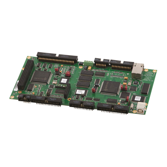
Turbo PMAC Clipper INTRODUCTION The Turbo PMAC Clipper is a multi-axis stand-alone controller. It has the full power of Turbo PMAC2 CPU and provides a minimum of 4 axes of servo or stepper control. It comes with 32 general-purpose digital I/O points, handwheel port, USB, Ethernet and RS-232 communications links. -
Page 10: Downloadable Turbo Pmac Script
// TURBO PMAC SCRIPT EXAMPLE P1=0 ; Set P1=0 at download Open PLC 1 Clear ; Open PLC Buffer 1, clear contents CMDP"Turbo PMAC Clipper Manual Test PLC" ; Send unsolicited response to host port P1=P1+1 ; Counter using variable P1 Disable PLC 1 ;... -
Page 11: Specifications
Turbo PMAC Clipper SPECIFICATIONS Part Number Connections and Software Setup... -
Page 12: Options
Turbo PMAC Clipper Options CPU Options 80MHz Turbo PMAC2 CPU (standard) 8Kx24 internal memory, 256Kx24 SRAM , 1MB flash memory 80MHz Turbo PMAC2 CPU 8Kx24 internal memory, 1Mx24 SRAM, 4M flash memory 240MHz Turbo PMAC2 CPU 192Kx24 internal memory, 1Mx24 SRAM, 4M flash memory Communication Options ... -
Page 13: Environmental Specifications
(overtravel limits), HOMEn (home flag), FAULTn (amplifier fault), and USERn. A power supply from 5 to 24V must be used to power the circuits related to these inputs. This power supply can be the same used to Turbo PMAC Clipper and can be connected from the TB1 terminal block or the J3 (JMACH1) connector. -
Page 14: Agency Approval And Safety
Turbo PMAC Clipper Agency Approval and Safety Item Description CE Mark EN61326-1 EN55011 Class A Group 1 EN61000-4-2 EN61000-4-3 EN61000-4-4 EN61000-4-5 EN61000-4-6 Flammability Class UL 94V-0 EMI: KN 11 EMS: KN 61000-6-2 사 용 자 안 내 문 이 기기는 업무용 환경에서 사용할 목적으로 적합성평가를 받은 기기로서 가정... -
Page 15: Receiving And Unpacking
If the Turbo PMAC Clipper is to be stored for several weeks before use, be sure that it is stored in a location that conforms to published storage humidity and temperature specifications. -
Page 16: Mounting
Turbo PMAC Clipper MOUNTING The location of the Turbo PMAC Clipper is important. Installation should be in an area that is protected from direct sunlight, corrosives, harmful gases or liquids, dust, metallic particles, and other contaminants. Exposure to these can reduce the operating life and degrade performance of the board. -
Page 17: Physical Specifications
Turbo PMAC Clipper Physical Specifications Board Dimensions and Layout Top View Rev106 Connections and Software Setup... -
Page 18: Connections And Software Setup
Turbo PMAC Clipper Hardware Reference Manual CONNECTIONS AND SOFTWARE SETUP Installation of electrical equipment is subject to many regulations including national, state, local, and industry guidelines and rules. The following are general recommendations but it is important that the integration be... -
Page 19: J2: Serial Port
$$$*** command. To change the baud rate setting on the Turbo PMAC Clipper, set I54 to the corresponding value of desired frequency. Restart the software (Pewin32Pro2), and adjust to the correct baud rate in the communication setup window. -
Page 20: J3: Machine Connector (Jmach1 Port)
Turbo PMAC Clipper Hardware Reference Manual J3: Machine Connector (JMACH1 Port) The primary machine interface connector is JMACH1, labeled J3 on the Turbo PMAC Clipper. It contains the pins for four channels of machine I/O: analog outputs, incremental encoder inputs, amplifier fault and enable signals and power-supply connections. - Page 21 Turbo PMAC Clipper Hardware Reference Manual CHC4/ Input Encoder C Channel Negative DAC1 Output Analog Output Positive 1 DAC2 Output Analog Output Positive 2 DAC1/ Output Analog Output Negative 1 DAC2/ Output Analog Output Negative 2 AENA1/ Output Amplifier-Enable 1...
- Page 22 Use an encoder cable with high quality shield. Note The standard encoder inputs on the Turbo PMAC Clipper are designed for differential quadrature type signals. Quadrature encoders provide two digital signals to determine the position of the motor. Each nominally with 50% duty cycle, and nominally 1/4 cycle apart.
-
Page 23: Setting Up Quadrature Encoders
PMAC Clipper or on top of the Acc-1P 5-8 axis board. Channels 1 – 4 of the ACC-51S correspond to PMAC channels 1 – 4 if the ACC-51S is connected to the main Turbo PMAC Clipper; channels 1 – 4 of the ACC-51S correspond to PMAC channels 5 –... - Page 24 Turbo PMAC Clipper Hardware Reference Manual ACC-51S channels 1 – 4 become PMAC channels 1 – 4 if ACC- 51S jumper E1 connects pins 2 and 3. ACC-51S channels 1 – 4 become PMAC channels 5 – 8 if ACC 51S jumper E1 connects pins 1 and 2.
-
Page 25: Counts Per User Units
Turbo PMAC Clipper Hardware Reference Manual The equivalent Turbo PMAC script code for 8-channel entries // Channel 1 I8000=$FF8000 ; High resolution interpolator (Clipper & Acc-51S) I8001=$078800 ; A/D converter address (Clipper & Acc-51S) I8002=$000000 ; Bias Term and Entry result (Clipper &... -
Page 26: Wiring The Dac Output
Turbo PMAC Clipper Hardware Reference Manual Wiring the DAC Output Example for Clipper Channel #1 Single Ended DAC Output Differential DAC Output Analog Analog DAC1- Device Device DAC1+ DAC1+ J3 (JMACH1) J3 (JMACH1) The analog outputs are intended to drive high-impedance inputs with no significant current draw (10mA max). -
Page 27: Amplifier Enable Signal (Aenan/Dirn)
Turbo PMAC Clipper Hardware Reference Manual Amplifier Enable Signal (AENAn/DIRn) Most amplifiers have an enable/disable input that permits complete shutdown of the amplifier regardless of the voltage of the command signal. PMAC’s AENA line is meant for this purpose. AENA1- is pin 33. -
Page 28: Amplifier Fault Signal (Fault-)
Turbo PMAC Clipper Hardware Reference Manual Amplifier Fault Signal (FAULT-) This input can take a signal from the amplifier so PMAC knows when the amplifier is having problems, and can shut down action. The polarity is programmable with I-variable Ixx24 (I124 for motor 1) and the return signal is ground (GND). -
Page 29: Optional Analog Inputs
Turbo PMAC Clipper Hardware Reference Manual Optional Analog Inputs The optional analog-to-digital converter inputs are ordered either through Option-12 on the Turbo PMAC Clipper or Option-2 on the axis expansion board. Each option provides two 12-bit analog inputs with a ±10Vdc range, and one 12-bit filtered PWM DAC output. -
Page 30: J4: Machine Connector (Jmach2 Port)
Turbo PMAC Clipper Hardware Reference Manual J4: Machine Connector (JMACH2 Port) This machine interface connector is labeled JMACH2 or J4 on the Turbo PMAC Clipper. It contains the pins for four channels of machine I/O: end-of-travel input flags, home flag and pulse-and-direction output signals. -
Page 31: Overtravel Limits And Home Switches
Turbo PMAC Clipper Hardware Reference Manual USER4 Input User Flag 3 PUL_3 Output Pulse Output 3 PUL_4 Output Pulse Output 4 DIR_3 Output Direction Output 3 DIR_4 Output Direction Output 4 EQU3 Output Encoder Comp-Equal EQU4 Output Encoder Comp-Equal B_WDO... - Page 32 Turbo PMAC Clipper Hardware Reference Manual Example for Normally Close Switch J4(JMACH2) USER 4 USER 3 NC NEG. LIMIT 4 NC NEG. LIMIT 3 NC POS. LIMIT 4 NC POS. LIMIT 3 HOME 4 HOME 3 USER 2 USER 1 NC NEG.
- Page 33 Turbo PMAC Clipper Hardware Reference Manual Example for 15-24V Proximity Switch J4(JMACH2) USER 4 USER 3 NC NEG. LIMIT 4 NC NEG. LIMIT 3 NC POS. LIMIT 4 NC POS. LIMIT 3 HOME 4 HOME 3 USER 2 USER 1 NC NEG.
-
Page 34: Limits And Flags [Axis 1- 4] Suggested M-Variables
Turbo PMAC Clipper Hardware Reference Manual While normally closed-to-ground switches are required for the overtravel limits inputs, the home switches could be either normally close or normally open types. The polarity is determined by the home sequence setup, through the I-variables Note I7mn2. -
Page 35: Step And Direction Pfm Output (To External Stepper Amplifier)
Turbo PMAC Clipper Hardware Reference Manual Step and Direction PFM Output (To External Stepper Amplifier) The Turbo PMAC Clipper or the Acc-1P has the capability of generating step and direction (Pulse Frequency Modulation) output signals to external stepper amplifiers. The step and direction outputs can be connected in single-ended configuration for 5V (input signal) amplifiers. -
Page 36: Compare Equal Outputs
Turbo PMAC Clipper Hardware Reference Manual Compare Equal Outputs The compare-equals (EQU) outputs have a dedicated use of providing a signal edge when an encoder position reaches a pre-loaded value. This is very useful for scanning and measurement applications. Instructions for use of these outputs are covered in detail in the Turbo PMAC User Manual. -
Page 37: J7: Machine Connector (Jmach3 Port)
Turbo PMAC Clipper Hardware Reference Manual J7: Machine Connector (JMACH3 Port) This machine interface connector is labeled JMACH3 or J7 on the Turbo PMAC Clipper. It contains the pins for four channels of U, V, and W flags normally used for hall device commutation. -
Page 38: J8: Thumbwheel Multiplexer Port (Jthw Port)
Thumbwheel Multiplexer Port on the JTHW connector has 8 inputs and 8 outputs at TTL levels. The output lines can be used to multiplex large numbers of inputs and outputs on the port, and Delta Tau provides accessory boards and software structures (special M-variable definitions) to capitalize on this feature. -
Page 39: Thumbwheel Port Digital Inputs And Outputs
Turbo PMAC Clipper Hardware Reference Manual The direction of the input and output lines on this connector are set by jumpers E14 and E15. If E14 is removed or E15 is installed then the multiplexing feature of the JTHW port cannot be used. -
Page 40: J9: General-Purpose Digital Inputs And Outputs (Jopt Port)
The direction of the input and output lines on this connector are set by jumpers E16 and E17. The 34-pin connector was designed for easy interface to OPTO-22 or equivalent optically isolated I/O modules. Delta Tau's Acc-21F is a six-foot cable for this purpose. - Page 41 Turbo PMAC Clipper Hardware Reference Manual Output Machine Output 3 11, 13 Common PMAC Common Output Machine Output 2 11, 13 Common PMAC Common Output Machine Output 1 11, 13 Common PMAC Common Output +5 Power I/O Common PMAC Common ...
-
Page 42: General Purpose I/Os (J6) Suggested M-Variables
Turbo PMAC Clipper Hardware Reference Manual General Purpose I/Os (J6) Suggested M-Variables The lines on the JOPT general-purpose I/O connector will be mapped into PMAC's address space in register Y:$78400. Typically, these I/O lines are accessed individually with M-variables. Following is a suggested set of M-variable definitions to use these data lines. -
Page 43: J10: Handwheel And Pulse/Dir Connector (Jhw/Pd Port)
Turbo PMAC Clipper Hardware Reference Manual J10: Handwheel and Pulse/Dir Connector (JHW/PD Port) JHW/PD port provides two Quadrature encoder inputs and PFM or PWM output pairs from the DSPGate2 supplemental channels 1* and 2*. J10 (JHW) Handwheel Encoder Connector 26-Pin Header... -
Page 44: J12: Ethernet Communications Port
This connector is used to establish USB (A-B type cable) communication between the host PC and the Turbo PMAC Clipper. This type of USB cable can be purchased at any local electronics or computer store. It may be ordered from Delta Tau as well. -
Page 45: Drive - Motor Setup
Turbo PMAC Clipper Hardware Reference Manual DRIVE - MOTOR SETUP The Turbo PMAC Clipper supports three types of outputs: Analog ±10V 12-bit Filtered PWM Analog ±10V 18-bit True DAC with Acc-8ES Pulse Frequency Modulation (PFM) The following chart summarizes the steps to implement for setting up a motor properly with the Turbo... -
Page 46: Filtered Pwm Output (Analog ±10V)
Both the resolution and the frequency of the Filtered PWM outputs are configured in software on the Turbo PMAC Clipper through the variable I7000. This variable also effects the phase and servo interrupts. Therefore as we change I7000 we will also have to change I7001 (phase clock divider), I7002 (servo clock divider), and I10 (servo interrupt time). -
Page 47: Clock Settings, Output Mode, Command Limit
Turbo PMAC Clipper Hardware Reference Manual Clock Settings, Output Mode, Command Limit Most commonly used and suggested clock settings in this mode allowing a good compromise are a 29.4 KHz PWM Frequency, 9.8 KHz Phase, and 2.45 KHZ Servo. DT Calculator Link... -
Page 48: I2T Protection: Ixx57, Ixx58
Example: A Turbo PMAC Clipper driving a torque-mode amplifier that has a gain of 3 amperes/volt and a continuous current rating of 10 amperes, with a motor rated to 12 amperes continuous. - Page 49 Absolute Serial Encoders (EnDat, SSI, BiSS, Yaskawa, Panasonic, Tamagawa, Mitutoyo): The Turbo PMAC Clipper has no control on the direction sense of the serial data stream (packets). There are no software parameters that allow changing the direction sense of absolute serial encoders.
-
Page 50: Position-Loop Pid Gains: Ixx30
Turbo PMAC Clipper Hardware Reference Manual If the motor/axis direction does not comply now with the machine design then negative jog commands can be issued for positive motion, and vice versa. Similarly, for motion programs, the motor can then assigned to a negative axis definition. -
Page 51: True Dac Output (±10V)
Example: A Turbo PMAC Clipper driving a torque-mode amplifier that has a gain of 3 amperes/volt and a continuous current rating of 10 amperes, with a motor rated to 12 amperes continuous. -
Page 52: Open Loop Test: Encoder/Decode
Turbo PMAC Clipper Hardware Reference Manual Open Loop Test: Encoder/Decode The open-loop test is critical to verify the direction sense of the encoder counting versus the command output. A positive command should create a positive velocity and a position counting in the positive direction;... -
Page 53: Position-Loop Pid Gains: Ixx30
Absolute Serial Encoders (EnDat, SSI, BiSS, Yaskawa, Panasonic, Tamagawa, Mitutoyo): The Turbo PMAC Clipper has no control on the direction sense of the serial data stream (packets). There are no software parameters that allow changing the direction sense of absolute serial encoders. - Page 54 Turbo PMAC Clipper Hardware Reference Manual At this point of the setup, the motor(s) is ready to accept Jog commands. Note Drive – Motor Setup...
-
Page 55: Pulse And Direction Output (Pfm)
Turbo PMAC Clipper Hardware Reference Manual Pulse and Direction Output (PFM) The Pulse and direction (Pulse Frequency Modulation) output pins are located on the J4 (JMACH2) connector. The stepper drive specifications dictate the choice of the maximum PFM clock frequency, and pulse width. -
Page 56: Pfm Setup Example
Turbo PMAC Clipper Hardware Reference Manual PFM Setup Example // Encoder Conversion Table, for channels 1-4 I8000=$C78000 ; Entry 1 incremental encoder, no extension I8001=$C78008 ; Entry 2 incremental encoder, no extension I8002=$C78010 ; Entry 3 incremental encoder, no extension I8003=$C78018 ;... -
Page 57: Issuing Open-Loop Commands
Turbo PMAC Clipper Hardware Reference Manual M407->Y:$7801C,8,16,S ; Channel 4, Min=0, Max= Calculated I469 // Channels 5-8 Suggested M-Variables, PFM command output M507->Y:$78104,8,16,S ; Channel 5, Min=0, Max= Calculated I569 (First Acc-1P) M607->Y:$7810C,8,16,S ; Channel 6, Min=0, Max= Calculated I669 (First Acc-1P) M707->Y:$78114,8,16,S ;... - Page 58 Turbo PMAC Clipper Hardware Reference Manual I603=$3506 I604=$3506 ; Channel 6 position and velocity pointers (First Acc-1P) I703=$3507 I704=$3507 ; Channel 7 position and velocity pointers (First Acc-1P) I803=$3508 I804=$3508 ; Channel 8 position and velocity pointers (First Acc-1P) I903=$3509 I904=$3509 ;...
- Page 59 Turbo PMAC Clipper Hardware Reference Manual // Channels 9-12 PID Gains (with default clock settings): I930,4,100 = 11190 ; Motors 9-12 Proportional Gain (Second Acc-1P) I931,4,100 = 0 ; Motors 9-12 Derivative Gain (Second Acc-1P) I932,4,100 = 15038 ; Motors 9-12 Velocity FeedForward Gain...
-
Page 60: Setup Of A Fifth Motor Using Opt-12 On The Clipper Board
Turbo PMAC Clipper Hardware Reference Manual Setup of a Fifth Motor Using Opt-12 on the Clipper Board The DSPGATE2A supplemental channels are set with I6800-6807. Set these to the same values as specified for the filtered PWM outputs (leave I6804-I6807 at default). - Page 61 Turbo PMAC Clipper Hardware Reference Manual The equivalent Turbo PMAC script code Settings: M32->X:$78400,0,8 ; Direction Control bits 0-7 (1=output, 0 = input) M34->X:$78400,8,8 ; Direction Control bits 8-15 (1=output, 0 = input) M40->X:$78404,0,24 ; Inversion control (0 = 0V, 1 = 5V) M42->Y:$78404,0,24 ;...
-
Page 62: Laser Control Output
Delta Tau and can be ordered at a later time with the same suffix. -
Page 63: Understanding Option-11A Capabilities
Turbo PMAC Clipper Hardware Reference Manual dependent on the laser and differs for different manufacturers. For example the laser shown in the above graph, requires a 5kHz signal with 0.5% duty cycle as its Tickle pulse. 75% Duty Cycle PWM Command... -
Page 64: Clock Settings
Turbo PMAC Clipper Hardware Reference Manual The following logic circuit is programmed as the Option-11A into the Lattice chip: As you can see, the idea is to switch the output between PWM_B signal and PFM signal based upon either of the EQU outputs. EQU outputs are fast responding outputs which can either be activated manually or based upon position compare feature of the PMAC. -
Page 65: Controlling The Output
Turbo PMAC Clipper Hardware Reference Manual 2. Issue SAVE and $$$. 3. Set I6807=0 and I7007=3 on the same line. 4. Issue SAVE and $$$. This will change the clock source from DSPGate1 to DSPGate2. Once the clock source is switched, the... - Page 66 Turbo PMAC Clipper Hardware Reference Manual #define EQU2_ON M212=1M211=1 #define EQU2_OFF M212=0M211=1 #define EQU3_ON M312=1M311=1 #define EQU3_OFF M312=0M311=1 #define EQU4_ON M412=1M411=1 #define EQU4_OFF M412=0M411=1 CTRL_TYP->Y:$078407,8,4 CTRL_INV->X:$078407,8,4 CTRL_DAT->Y:$078403,8,4 CTRL_DIR->X:$078403,8,4 PWM_CMD_VAL->Y:$078414,8,16,S PFM_CMD_VAL->Y:$07841C,0,24,S M111->X:$078005,11 ; ENC1 compare initial state write enable M112->X:$078005,12 ; ENC1 compare initial state M116->X:$078000,9 ;...
-
Page 67: Troubleshooting
Top assembly last ship date (e.g. if it has ever been back for repair) This page is strictly for identification purposes. Some information may not be meaningful to the user and pertains to Delta Tau’s internal use only. Note... -
Page 68: Write-Protect Disable - E8 Jumper
Reloading communication boot and firmware These functions are accessible through the Configure Ethernet 100 BaseT utility found in the Windows Start menu under PMAC Executive Pro2 Suite > Delta Tau Common > Configure Ethernet 100 BaseT: This utility only works with USB communication. -
Page 69: Changing Ip Address, Gateway Ip, Gateway Mask
Turbo PMAC Clipper Hardware Reference Manual Changing IP Address, Gateway IP, Gateway Mask In order to change any of these addresses, install the E8 jumper prior to pressing the corresponding Store button. The following steps ensure proper configuration: Step1: Change the desired address field... -
Page 70: Enabling Modbus
MAC ID of the Clipper unit. This is found in the lower left hand side of the Ethernet 100 Base T utility. Upon purchase of the ModBus Option, a .BIN file is obtained from Delta Tau for this purpose. -
Page 71: Reloading Boot And Communication Firmware
Turbo PMAC Clipper Hardware Reference Manual Reloading Boot and Communication Firmware The boot and firmware .IIC files are required for this procedure. They are normally obtained directly from Delta Tau, or downloaded from the PMAC forum Webpage. The following steps ensure proper... -
Page 72: Reloading Pmac Firmware - E13 Jumper
Turbo PMAC Clipper Hardware Reference Manual Reloading PMAC firmware – E13 Jumper E13 jumper is putting Clipper into Bootstrap mode. The following steps ensure proper firmware reload/upgrade. Step1: Jumper the E13 while power is off. Step2: Power up the Clipper. - Page 73 Turbo PMAC Clipper Hardware Reference Manual Step5: The download utility will prompt for a .BIN file. MAKE SURE you open the correct file. The PMAC firmware file for Turbo PMAC Clipper MUST ALWAYS be TURBO2.BIN. Note Step6: Wait until download is finished, and click done.
-
Page 74: Re-Initialization Jumper (Factory Reset)
Turbo PMAC Clipper Hardware Reference Manual Re-initialization jumper (Factory Reset) The E3 jumper is used to reset the Turbo PMAC Clipper back to factory default settings, global reset. Issuing a SAVE after power up (with the E3 jumper) will permanently erase any user configured parameters. -
Page 75: Appendix A: E-Point Jumpers
Turbo PMAC Clipper Hardware Reference Manual APPENDIX A: E-POINT JUMPERS E0: Forced Reset Control Jumper Configuration Default Factory use only. The board will not operate with E0 Factory installed E1 – E2: Serial Port Selection (rev 102 and below only) -
Page 76: E6: Adc Inputs Enable
Turbo PMAC Clipper Hardware Reference Manual Version 101 and lower Jumper Configuration Default Factory use only. The board will not communicate via 1 – 2 Ethernet unless jumper is installed on pins 1 to 2 E6: ADC Inputs Enable... -
Page 77: E13: Power-Up/Reset Load Source
Turbo PMAC Clipper Hardware Reference Manual E13: Power-Up/Reset Load Source Jumper Configuration Default 1 to 2 to reload firmware through serial or bus port Factory E13: Remove jumper for normal operation E14- E17: Ports Direction Control Jumper Configuration Default ... -
Page 78: Appendix B: Schematics
Turbo PMAC Clipper Hardware Reference Manual APPENDIX B: SCHEMATICS Appendix B... - Page 79 Turbo PMAC Clipper Hardware Reference Manual Appendix B...
- Page 80 Turbo PMAC Clipper Hardware Reference Manual Appendix B...
- Page 81 Turbo PMAC Clipper Hardware Reference Manual Appendix B...
- Page 82 Turbo PMAC Clipper Hardware Reference Manual Appendix B...
- Page 83 Turbo PMAC Clipper Hardware Reference Manual Appendix B...
- Page 84 Turbo PMAC Clipper Hardware Reference Manual Appendix B...
Need help?
Do you have a question about the Turbo PMAC Clipper and is the answer not in the manual?
Questions and answers