Sign In
Upload
Manuals
Brands
Delta Tau Manuals
Controller
PMAC Lite
Delta Tau PMAC Lite Manuals
Manuals and User Guides for Delta Tau PMAC Lite. We have
2
Delta Tau PMAC Lite manuals available for free PDF download: Reference Manual, Hardware Reference Manual
Delta Tau PMAC Lite Reference Manual (108 pages)
Brand:
Delta Tau
| Category:
Controller
| Size: 2 MB
Table of Contents
Table of Contents
5
Introduction
9
Description of PMAC
9
Types of PMAC
10
PMAC PC or PMAC VME Features
10
Pmac Pc
10
PMAC Lite
10
Pmac Vme
10
Pmac Std
10
PMAC Mini
11
Pmac2
12
PMAC2 Ultralite
12
Turbo PMAC Family
12
PMAC Connectors and Indicators
13
Display Port Outputs (JDISP Port)
13
Control-Panel Port I/O (JPAN Port)
13
Thumbwheel Multiplexer Port I/O (JTHW Port)
13
Serial Port Connection
13
General-Purpose Digital Inputs and Outputs (JOPTO Port)
13
Machine Connectors
13
LED Indicators
13
Working with PMAC
14
Hardware Setup
14
Software Setup
14
Programming PMAC
15
PMAC Tasks
15
Single Character I/O
16
Commutation Update
16
Servo Update
16
VME Mailbox Processing
17
Real-Time Interrupt Tasks
17
Background Tasks
17
Observations
18
Priority Level Optimization
19
Pmac Executive Program, Pewin
21
Configuring PEWIN
21
Quick Plot Feature
22
Saving and Retrieving PMAC Parameters
23
The Watch and Position Windows
23
Uploading and Downloading Files
23
Using MACRO Names and Include Files
23
Downloading Compiled Plccs
24
PID Tuning Utility
24
Other Features
27
Installing and Configuring Pmac
29
Jumpers Setup
29
Serial Connections
29
Establishing Host Communications
30
Terminal Mode Communications
30
Resetting PMAC for First Time Use
31
Connections
31
Power Supplies
31
Digital Power Supply
31
Analog Power Supply
31
Flags Power Supply (Optional)
32
Overtravel Limits and Home Switches
32
Disabling the Overtravel Limits Flags
32
Types of Overtravel Limits
32
Home Switches
33
Pmacpack and PMAC2 Flag Inputs
33
Checking the Flag Inputs
33
Motor Signals Connections
34
Incremental Encoder Connection
34
Checking the Encoder Inputs
34
Checking the DAC Outputs
34
DAC Output Signals
35
Amplifier Enable Signal (Aenax/Dirn)
35
Amplifier Fault Signal (Faultn)
36
General-Purpose Digital Inputs and Outputs (JOPTO Port)
36
Machine Connections Example
37
Programming Pmac
39
Online Commands
39
Buffered (Program) Commands
40
Computational Features
40
I-Variables
40
P-Variables
41
Q-Variables
41
M-Variables
42
Array Capabilities
43
Operators
44
Functions
44
Comparators
45
User-Written Phase and User-Written Servo Algorithms
45
Memory Map
45
User Buffer Storage Space
46
Encoder Conversion Table
46
Conversion Table Structure
47
Further Position Processing
47
PMAC Position Registers
48
Homing Search Moves
49
Command and Send Statements
50
Motion Programs
51
How PMAC Executes a Motion Program
51
Coordinate Systems
52
Axis Definitions
52
Axis Definition Statements
53
Writing a Motion Program
53
Running a Motion Program
54
Subroutines and Subprograms
55
Passing Arguments to Subroutines
56
G, M, T, and D-Codes (Machine-Tool Style Programs)
56
Linear Blended Moves
57
Observations
58
Circular Interpolation
62
Splined Moves
64
PVT-Mode Moves
64
Other Programming Features
66
Rotary Motion Program Buffers
66
Internal Time Base, the Feedrate Override
66
External Time Base Control (Electronic Cams)
67
Position Following (Electronic Gearing)
67
Cutter Radius Compensation
67
Synchronous M-Variable Assignment
68
Synchronizing PMAC to Other Pmacs
68
Axis Transformation Matrices
68
Position-Capture and Position-Compare Functions
68
Learning a Motion Program
68
Plc Programs
69
Entering a PLC Program
70
PLC Program Structure
71
Calculation Statements
71
Conditional Statements
71
Level-Triggered Conditions
71
Edge-Triggered Conditions
71
WHILE Loops
72
COMMAND and SEND Statements
72
Timers
73
Compiled PLC Programs
74
Troubleshooting
75
Resetting PMAC to Factory Defaults
75
The Watchdog Timer (Red LED)
75
Establishing Communications
76
General
76
Bus Communications
77
Serial Communications
77
Motor Parameters
77
Motion Programs
78
PLC Programs
79
Appendix A - Pmac Error Code Summary
81
I6, Error Reporting Mode
81
Appendix B - Pmac I-Variables Summary
83
Appendix C - Pmac On-Line (Immediate) Commands
89
Appendix D - Pmac Program Command Specifications
95
Appendix E - Motor Suggested M-Variable Definitions
99
Appendix F - I/O Suggested M-Variable Definitions
103
Appendix G - Acc-8D/8P Pinout Descriptions
107
Advertisement
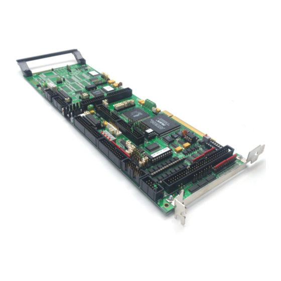
Delta Tau PMAC Lite Hardware Reference Manual (64 pages)
PCI Format 4-Axis Control Board
Brand:
Delta Tau
| Category:
PCI Card
| Size: 3 MB
Table of Contents
Table of Contents
6
Introduction
10
Board Configuration
10
Base Version
10
Option 2: Dual-Ported RAM
10
Option 5Xf: CPU Speed Options
10
Option 6: Extended Servo Algorithm Firmware
11
Option 6L: Special Lookahead Firmware
11
Option 10: Firmware Version Specification
11
Option 12: Analog-To-Digital Converters
11
Option 15: V-To-F Converter for Analog Input
11
Option 16: Battery-Backed Parameter Memory
11
Hardware Setup
12
Power-Supply Configuration Jumpers
12
Clock Configuration Jumpers
13
Encoder Configuration Jumpers
13
Board Reset/Save Jumpers
14
Communication Jumpers
14
I/O Configuration Jumpers
14
Reserved Configuration Jumpers
15
CPU Jumper Configuration
15
Resistor Pack Configuration: Termination Resistors
16
Resistor Pack Configuration: Differential or Single-Ended Encoder Selection
16
Machine Connections
18
Mounting
18
Power Supplies
18
Digital Power Supply
18
Analog Power Supply
18
Overtravel Limits and Home Switches
19
Resistor Pack Configuration: Flag and Digital Inputs Voltage Selection
19
Types of Overtravel Limits
19
Home Switches
19
Motor Signals Connections (JMACH Connectors)
20
Incremental Encoder Connection
20
DAC Output Signals
20
Amplifier Enable Signal (Aenax/Dirn)
21
Amplifier Fault Signal (Faultn)
21
General-Purpose Digital Inputs and Outputs (JOPTO Port)
22
Control-Panel Port I/O (JPAN Port)
23
Command Inputs
23
Selector Inputs
24
Alternate Use
24
Reset Input
24
Handwheel Inputs
24
Optional Voltage to Frequency Converter
24
Thumbwheel Multiplexer Port (JTHW Port)
25
Optional Analog Inputs (JANA Port)
25
Compare Equal Outputs Port (JEQU Port)
26
Serial Port (JRS422 Port)
26
Machine Connections Example
28
Software Setup
30
Communications
30
PMAC I-Variables
30
Operational Frequency and Baud Rate Setup
30
Serial Addressing Card Number
31
Option 16 Supplemental Battery-Backed Memory
32
Hardware Reference Summary
34
Board Dimensions - Part Number 603657-100
34
Board Layout Part Number 603657-10X
35
Connectors and Indicators
37
J1 - Display Port (JDISP Port)
37
J2 - Control-Panel Port (JPAN Port)
37
J3 - Thumbwheel Multiplexer Port (JTHW Port)
37
J4 - Serial Port (JRS422 Port)
37
J5 - General-Purpose Digital Inputs and Outputs (JOPTO Port)
37
J6 - Expansion Port (JXIO Port)
37
J8 - Machine Connectors (JMACH Port)
37
J9 - Compare Equal Outputs Port (JEQU Port)
37
J17 - Serial Port (JRS232 Port)
37
J31 - Optional Universal Serial Bus Port (JUSB Port)
38
JS1 - Expansion Ports (JS1 Port)
38
TB1 - Power Supply Terminal Block (JPWR Connector)
38
LED Indicators
38
Fuse
38
E-Point Jumper Descriptions
40
E0: Reserved for Future Use
40
E1 - E2: Machine Output Supply Voltage Configure
40
E3 - E6: Servo Clock Frequency Control
41
E7: Machine Input Source/Sink Control
41
E10A, B, C: Flash Memory Bank Select
42
E17A-D: Amplifier Enable/Direction Polarity Control
42
E18 - E20: Power-Up/Reset Load Source
42
E21: Power-Up/Reset Load Source
43
E22 - E23: Control Panel Handwheel Enable
43
E28: Following Error/Watchdog Timer Signal Control
43
E29 - E33: Phase Clock Frequency Control
44
E34A - E38: Encoder Sampling Clock Frequency Control
44
E40 - E43: Clock Direction Control
44
E44 - E47: Serial Port Baud Rate
45
E48: CPU Clock Frequency Control (Option CPU Section)
45
E49: Serial Communications Parity Control
46
E50: Flash Save Enable/Disable
46
E51: Normal/Re-Initializing Power-Up
46
E55 - E65: Host Interrupt Signal Select
46
E72 - E73: Panel Analog Time Base Signal Enable
47
E74 - E75: Clock Output Control for External Interpolation
47
E85: Host-Supplied Analog Power Source Enable
47
E87 - E88: Host-Supplied Analog Power Source Enable
48
E89: Amplifier-Supplied Switch Pull-Up Enable
48
E90: Host-Supplied Switch Pull-Up Enable
48
E98: DAC/ADC Clock Frequency Control
49
E100: Output Flag Supply Select
49
E101 - E102: Motors 1-4 Amplifier Enable Output Configure
49
E109: Reserved for Future Use
50
110: Serial Port Configure
50
E111: Clock Lines Output Enable
50
E119: Watchdog Disable Jumper
50
E122: XIN Feature Selection
50
Mating Connectors
52
Base Board Connectors
52
J1 (Jdisp)/Display
52
J2 (Jpan)/Control Panel
52
J3 (Jthw)/Multiplexer Port
52
J4 (JRS422)/RS232 or 422/Serial Communications
52
J5 (Jopt)/Opto I/O
52
J6 (Jxio)/Expansion Board
52
J8 (Jmach)/Machine Connector
52
JS1/A-D Inputs 1-4
52
Jana/Analog Inputs Option
53
Connector Pinouts
54
J1: Display Port Connector
54
J2: Control Panel Port Connector
55
J3: Multiplexer Port Connector
56
J4: Serial Port Connector
57
J5: I/O Port Connector
58
J6: Auxiliary I/O Port Connector
59
J8: Machine Port Connector
60
J8: Machine Port Connector
61
J9 (JEQU): Position-Compare Connector
62
J30 (JANA) Analog Input Port Connector (Optional)
62
J31 (JUSB) Universal Serial Bus Port (Optional)
63
JS1: A/D Port 1 Connector
63
TB1 (JPWR) External Power Supply Connection
63
Advertisement
Related Products
Delta Tau PMAC PC
Delta Tau PMAC Mini
Delta Tau Turbo PMAC2 3U
Delta Tau Turbo PMAC2 PC
Delta Tau PMAC VME
Delta Tau PMAC STD
Delta Tau Power PMAC Clipper
Delta Tau Turbo PMAC2 PCI Ultralite
Delta Tau PMAC2-PC LITE
Delta Tau PMAC 1.5 Lite
Delta Tau Categories
Controller
Computer Hardware
Amplifier
Power Supply
PCI Card
More Delta Tau Manuals
Login
Sign In
OR
Sign in with Facebook
Sign in with Google
Upload manual
Upload from disk
Upload from URL