
Related Manuals for Delta Tau PMAC 1.5 Lite


Summary of Contents for Delta Tau PMAC 1.5 Lite
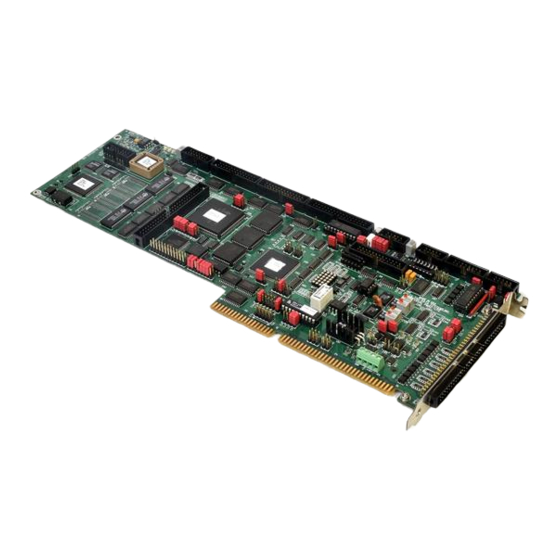
- Page 1 (217) 352-9330 | Click HERE Find the OMRON / Delta Tau Universal PMAC-Lite at our website:...
- Page 2 1HARDWARE REFERENCE MANUAL PMAC 1.5 Lite Programmable Multi-Axis Controller 3Ax-602402-xHxx July 10, 2003 Single Source Machine Control Power // Flexibility // Ease of Use 21314 Lassen Street Chatsworth, CA 91311 // Tel. (818) 998-2095 Fax. (818) 998-7807 // www.deltatau.com Artisan Technology Group - Quality Instrumentation ... Guaranteed | (888) 88-SOURCE | www.artisantg.com...
- Page 3 Copyright Information © 2003 Delta Tau Data Systems, Inc. All rights reserved. This document is furnished for the customers of Delta Tau Data Systems, Inc. Other uses are unauthorized without written permission of Delta Tau Data Systems, Inc. Information contained in this manual may be updated from time-to-time due to product improvements, etc., and may not...
-
Page 4: Table Of Contents
PMAC-Lite Hardware Reference Table of Contents INTRODUCTION ..............................1 Overview ..................................1 Board Configuration..............................1 Base Version................................1 Option 2: Dual Ported RAM ...........................2 Option 5: CPU & Memory Configurations......................2 Option 6: Extended Servo Algorithm ........................2 Option 7: Plate Mounting ............................2 Option 8: High-Accuracy Clock Crystal .........................2 Option 9: RS-422 Interface (now standard)......................2 Option 10: Firmware Version Specification ......................2 Option 14: Replacement of flag Opto-Isolators with Socketed Shunts ..............3... - Page 5 PMAC-Lite Hardware Reference E100: Output Flag Supply Select ..........................23 E101 – E102: Output Flag Supply Voltage Configure....................24 E103: Watchdog Disable Jumper ..........................24 E106: Firmware Reload Enable..........................25 E110: Expansion Port Configuration.........................25 HOST PC-AT I/O ADDRESS MAP ........................27 BUS ADDRESS JUMPER SETUP ........................29 From Jumper Configuration To Address ......................29 From Address to Jumper Configuration .......................29 MATING CONNECTORS .............................31...
-
Page 6: Introduction
PMAC-Lite Hardware Reference INTRODUCTION Overview The PMAC-Lite is a member of the PMAC(1) family of boards optimized for interface to traditional servo drives with single analog inputs representing velocity or torque commands. Its software is capable of eight axes of control. It has four channels of on-board axis interface circuitry. It can also support up to 8 channels of off-board axis interface circuitry through its expansion port, connected to an ACC-24P board. -
Page 7: Option 2: Dual Ported Ram
PMAC-Lite Hardware Reference Option 2: Dual Ported RAM Dual-ported RAM provides a high-speed communications path for bus communications with the host computer through a bank of shared memory. DPRAM is advised if more than about 100 data items per second are to be passed between the controller and the host computer in either direction. Option 2 provides an on-board 8k x 16 bank of dual-ported RAM. -
Page 8: Option 14: Replacement Of Flag Opto-Isolators With Socketed Shunts
PMAC-Lite Hardware Reference Option 14: Replacement of flag Opto-Isolators with Socketed Shunts Normally, the flag inputs on all servo channels have opto-isolator circuits that require 12 to 24V inputs to turn on. When the ACC-8D Option 8 Analog Encoder Interpolator is used on a pair of channels, it uses the flag inputs on the second (even-numbered) channel to provide “sub-count”... -
Page 9: Compatibility Issues
Raised Bottom Edge. The higher bottom edge moves the lower left mounting hole for standoffs up 12.7 mm (0.5 in). If you are using standoff mounting, and cannot move the matching mounting hole, contact Delta Tau for free offset standoffs. •... -
Page 10: Basic Specifications
PMAC-Lite Hardware Reference Basic Specifications Physical Specifications Size: 33.5cm x 9.9cm x 3.8cm (13.2" x 3.9" x 1.4") Weight: ¾ lb. Temperature Operating: 0°C to 60°C (32°)F to 140°F) Storage: 12°C to 82°C (10°F to 180°F) Humidity: 10% to 95%, noncondensing Electrical Specifications Power: 1.5A @ +5V (±5%) (7.5W) - Page 11 PMAC-Lite Hardware Reference Introduction Artisan Technology Group - Quality Instrumentation ... Guaranteed | (888) 88-SOURCE | www.artisantg.com...
-
Page 12: Layout Diagram
PMAC-Lite Hardware Reference LAYOUT DIAGRAM E107 E108 Layout Diagram Artisan Technology Group - Quality Instrumentation ... Guaranteed | (888) 88-SOURCE | www.artisantg.com... - Page 13 PMAC-Lite Hardware Reference Layout Diagram Artisan Technology Group - Quality Instrumentation ... Guaranteed | (888) 88-SOURCE | www.artisantg.com...
-
Page 14: E-Point Descriptions
PMAC-Lite Hardware Reference E-POINT DESCRIPTIONS E1 - E2: Machine Output Supply Voltage Configure E Point & Physical Location Description Default Layout 1-2 Jumper CAUTION installed The jumper setting must match the type of driver IC, or damage to the IC will result. -
Page 15: E3 - E6: Servo Clock Frequency Control
PMAC-Lite Hardware Reference E3 - E6: Servo Clock Frequency Control The servo clock (which determines how often the servo loop is closed) is derived from the phase clock (see E98, E29 - E33) through a “divide-by-N” counter. Jumpers E3 through E6 control this dividing function. -
Page 16: E7: Machine Input Source/Sink Control
PMAC-Lite Hardware Reference E7: Machine Input Source/Sink Control E Point & Physical Location Description Default Layout Jump pin 1 to 2 to apply +5V to input 1-2 Jumper reference resistor sip pack; this will installed bias MI1 to MI8 inputs to +5V for “OFF”... -
Page 17: E17A-D: Amplifier Enable/Direction Polarity Control
PMAC-Lite Hardware Reference E17A-D: Amplifier Enable/Direction Polarity Control E Point & Physical Location Description Default Layout Jump 1-2 for high-true AENA1 No jumper E17A Remove jumper for low-true AENA1 installed Jump 1-2 for high-true AENA2 No jumper E17B Remove jumper for low-true AENA2 installed Jump 1-2 for high-true AENA3 No jumper... -
Page 18: E24 - E27: Encoder Single-Ended/Differential Control
PMAC-Lite Hardware Reference E24 - E27: Encoder Single-Ended/Differential Control E-Point & Physical Location Description Default Layout ENC 4 through 1: 1-2 Jumper Jump pin 1 to 2 to tie complementary installed for encoder inputs to 2.5V E24 - E27 Jump pin 2 to 3 to tie complementary E24: ENC 4 encoder inputs to 5V E25: ENC 3... -
Page 19: E29 - E33: Phase Clock Frequency Control
PMAC-Lite Hardware Reference E29 - E33: Phase Clock Frequency Control Jumpers E29 through E33 control the speed of the phase clock, and, indirectly, the servo clock, which is divided down from the phase clock (see E3 - E6). No more than 1 of these 5 jumpers may be on at a time. PHASE Clock Frequency E98 Connects E98 Connects... - Page 20 PMAC-Lite Hardware Reference Card Address Servo & Phase Default & Physical Clock Direction Layout E40 E41 E42 E43 C2 C2 C2 C2 Output (ALL ON) Input Input Input Input Input Input Input Input Input Input Input Input Input Input Input Note: If any jumper E40 –...
-
Page 21: E44 - E47: Serial Baud Rate Control
PMAC-Lite Hardware Reference E44 - E47: Serial Baud Rate Control Jumpers E44 - E47 control what baud rate to use for serial communications. Any character received over the bus causes PMAC to use the bus for its standard communications. The serial port is disabled when E44-E47 are all on. -
Page 22: E48: Cpu Clock Frequency Control
Operation in this mode is done completely at the user’s own risk; Delta Tau can accept no responsibility for the operation of the PMAC or the machine under these conditions. -
Page 23: E54 - E65: Host Interrupt Signal Select
PMAC-Lite Hardware Reference E54 - E65: Host Interrupt Signal Select E Point & Location Description Default Physical Layout Jump pin 1 to 2 to allow EQU4 to No jumper interrupt host-PC at PMAC interrupt installed level IR7 Jump pin 1 to 2 to allow EQU3 to No jumper interrupt host-PC at PMAC interrupt installed... -
Page 24: E66 - E71: Bus Base Hardware Address (Low Bits)
PMAC-Lite Hardware Reference E66 - E71: Bus Base Hardware Address (Low Bits) These jumpers work with E91 & E92 to set the base address of PMAC-Lite on the PC bus. See PMAC- Lite Bus Addressing below for details on how to set these jumpers. E Point &... -
Page 25: E76 - E84: Host Interrupt Signal Select
PMAC-Lite Hardware Reference E76 - E84: Host Interrupt Signal Select E Point & Location Description Default Physical Layout Jump pin 1 to 2 to allow PMAC- No jumper Interrupt to host-PC on IRQ14 installed Jump pin 1 to 2 to allow PMAC- No jumper Interrupt to host-PC on IRQ15 installed... -
Page 26: E85: Host-Supplied Analog Power Source Enable
PMAC-Lite Hardware Reference E85: Host-Supplied Analog Power Source Enable E Point & Location Description Default Physical Layout Jump pin 1 to pin 2 to allow A+14V to No jumper come from PC bus (ties amplifier and PMAC-Lite power supply together. Defeats OPTO coupling) Note that if E85 is changed, E88 and E87 must also be changed. -
Page 27: E89: Amplifier-Supplied Switch Pull-Up Enable
PMAC-Lite Hardware Reference E89: Amplifier-Supplied Switch Pull-Up Enable E Point & Location Description Default Physical Layout Jump pin 1 to 2 to use A+15V on J8 Jumper installed (JMACH1) pin 59 as supply for input flags. Remove jumper to use A+15V/OPT+V from J7 pin 59 as supply for input flags. -
Page 28: E93 - E94: Reset From Bus By Software Enable
PMAC-Lite Hardware Reference E93 - E94: Reset from Bus by Software Enable E Point & Location Description Default Physical Layout Jump 1-2 to provide hardware reset of No jumper PMAC-Lite under the software control of the host-PC. PMAC-Lite will power up and stay in the reset state until PC software writes 40 HEX to Base +12. -
Page 29: E101 - E102: Output Flag Supply Voltage Configure
PMAC-Lite Hardware Reference E101 – E102: Output Flag Supply Voltage Configure E Point & Location Description Default Physical Layout 1-2 Jumper E101 CAUTION installed The jumper setting must match the type of driver IC, or damage to the IC will result. Jump pin 1 to 2 to apply +V (12V to 24V) to pin 10 of U54 (should be ULN2803A for sink output... -
Page 30: E106: Firmware Reload Enable
PMAC-Lite Hardware Reference E106: Firmware Reload Enable E Point & Location Description Default Physical Layout Remove jumper for normal operation. No jumper E106 installed Jump pin 1 to 2 to lock card in reset state for programming of on-board logic (for factory use only). Jump pin 2 to 3 to reload firmware through serial or bus port on power- up/reset. - Page 31 PMAC-Lite Hardware Reference E-Point Descriptions Artisan Technology Group - Quality Instrumentation ... Guaranteed | (888) 88-SOURCE | www.artisantg.com...
-
Page 32: Host Pc-At I/O Address Map
PMAC-Lite Hardware Reference HOST PC-AT I/O ADDRESS MAP Hex Range Dec Range Usage 000-01F 0-31 DMA Controller 1 8237A-5 020-03F 32-63 Interrupt Controller 1 8259A 040-05F 64-67 Timer 8254-2 060-06F 96-111 8042 (Keyboard) 070-07F 112-127 Real-time clock, NMI mask 080-09F 128-159 DMA Page Registers 0A0-0BF... - Page 33 PMAC-Lite Hardware Reference Host PC-AT I/O Address Map Artisan Technology Group - Quality Instrumentation ... Guaranteed | (888) 88-SOURCE | www.artisantg.com...
-
Page 34: Bus Address Jumper Setup
PMAC-Lite Hardware Reference BUS ADDRESS JUMPER SETUP Jumpers E91, E92, E66, E67, E68, E69, E70, and E71 on the PMAC-Lite determine the base address of the card in the I/O space of the host PC’s expansion bus. Together, they form a binary number that specifies the 16 consecutive addresses on the bus where the card can be found. - Page 35 PMAC-Lite Hardware Reference 3. Take the second hex digit and convert it to binary. The binary digits represent bits 7 through 4 of the base address. Assign each binary digit to jumpers as follows: Bit # 7(MSB) 4(LSB) Jumper Digit Value Setting for 1 Setting for 0 Example 1: You wish to set up the card to be at base address 992 decimal on the PC expansion bus.
-
Page 36: Mating Connectors
This section lists several options for each connector. Choose an appropriate one for your application. J1 (JDISP)/Display Port Two 14-pin female flat cable connector Delta Tau P/N 014-R00F14-0K0 T&B Ansley P/N 609-1441 171-14 T&B Ansley standard flat cable stranded 14-wire... -
Page 37: J9 (Jexp)/Expansion Port
One 62-pin card edge connector with solder pierced eyelets Delta Tau P/N 014-000F62-SCO Viking P/N 3KH 31/9 JN12 card edge connector pierced solder eyelets. P2 (AT Bus) One 36-pin card edge connector with solder pierced eyelets Delta Tau P/N 014-000 F36-SCO Viking P/N 3KH 18/9 JN12 card edge connector pierced solder eyelets. Mating Connectors... -
Page 38: Connector Pinouts
PMAC-Lite Hardware Reference CONNECTOR PINOUTS J1 (JDISP): Display Port Connector J1 JDISP (14-Pin Connector) Front View Pin # Symbol Function Description Notes Output +5V Power Power Supply Out Common PMAC Common Output Read Strobe TTL Signal Out Output Contrast Adjust VEE 0 to+5Vdc * Output Display Enable... -
Page 39: J2 (Jpan): Control Panel Port Connector
PMAC-Lite Hardware Reference J2 (JPAN): Control Panel Port Connector J2 JPAN (26-Pin Connector) Front View Pin # Symbol Function Description Notes Output +5V Power For remote panel Common PMAC Common FPD0/ Input Motor/C.S. Select Bit 0 Low is TRUE JOG-/ Input JOG IN - DIR. -
Page 40: J3 (Jthw): Multiplexer Port Connector
PMAC-Lite Hardware Reference J3 (JTHW): Multiplexer Port Connector J3 JTHW (26-Pin Connector) Front View Pin # Symbol Function Description Notes Common PMAC Common Common PMAC Common DAT0 Input Data-0 Input Data input from multiplexed accessory SEL0 Output Select-0 Output Multiplexer select output DAT1 Input Data-1 Input... -
Page 41: J4 (Jrs232) Serial Port Connector
PMAC-Lite Hardware Reference J4 (JRS232) Serial Port Connector J4 JRS232 (10-Pin Connector) Front View Pin # Symbol Function Description Notes PHASE Output Phasing Clock Bidirect Data Term Ready Tied to “DSR” TXD/ Input Receive Data Host transmit data Input Clear to Send Host ready bit RXD/ Output... -
Page 42: J4A (Jrs422): Serial Port Connector
PMAC-Lite Hardware Reference J4A (JRS422): Serial Port Connector J4A JRS422 (26-Pin Connector) Front View Pin # Symbol Function Description Notes CHASSI Common PMAC Common S+5V Output +5VDC Supply Deactivated by “E8” Input Receive Data Diff. I/O Low True= ** Input Receive Data Diff. -
Page 43: J5 (Jopto): I/O Port Connector
PMAC-Lite Hardware Reference J5 (JOPTO): I/O Port Connector J5 JOPTO (34-Pin Connector) Front View Pin # Symbol Function Description Notes Input Machine Input 8 Low is True Common PMAC Common Input Machine Input 7 Low is True Common PMAC Common Input Machine Input 6 Low is True... -
Page 44: J6 (Jxio): Auxiliary I/O Port Connector
PMAC-Lite Hardware Reference J6 (JXIO): Auxiliary I/O Port Connector J6 JXIO (10-Pin Connector) Front View Pin # Symbol Function Description Notes CHA1 Input Enc. A CH. Pos. From ACC-14 board CHB1 Input Enc. B CH. Pos. From ACC-14 board CHC1 Input Enc. -
Page 45: J8 (Jequ): Position-Compare Connector
PMAC-Lite Hardware Reference J8 (JEQU): Position-Compare Connector J8 JEQU (10-Pin Connector) Front View Pin # Symbol Function Description Notes EQU1/ Output Enc. 1 Comp-EQ Low is True EQU2/ Output Enc. 2 Comp.-EQ Low is True EQU3/ Output Enc. 3 Comp.-EQ Low is True EQU4/ Output... -
Page 46: J11 (Jmach1): Machine Port Connector
PMAC-Lite Hardware Reference J11 (JMACH1): Machine Port Connector J11 JMACH1 (60-Pin Header) Pin # Symbol Function Description Notes Output +5V Power For encoders, 1 Output +5V Power For encoders, 1 Common Digital Common Common Digital Common CHC3 Input Encoder C CH. POS CHC4 Input Encoder C CH. - Page 47 PMAC-Lite Hardware Reference J11 JMACH1 (60-Pin Header) (Continued) Pin # Symbol Function Description Notes DAC1/ Output Analog Out Neg. 1 DAC2/ Output Analog Out Neg. 2 AENA1/DIR1 Output Amp-Ena/Dir. 1 AENA2/DIR2 Output Amp-Ena/Dir. 2 FAULT1 Input Amp-Fault 1 FAULT2 Input Amp-Fault 2 +LIM1 Input...
-
Page 48: Tb1 (Jpwr): Power Supply
PMAC-Lite Hardware Reference TB1 (JPWR): Power Supply Pin # Symbol Function Description Notes Common Reference Voltage Input Positive Supply Voltage Supplies all PMAC digital circuits +12V Input Positive Supply Voltage Ref to digital GND -12V Input Negative Supply Voltage Ref to digital GND This terminal block can be used to provide the input for the power supply for the circuits on the PMAC board when it is not in a bus configuration.
Need help?
Do you have a question about the PMAC 1.5 Lite and is the answer not in the manual?
Questions and answers