Table of Contents
Advertisement
^1
User Manual
^2
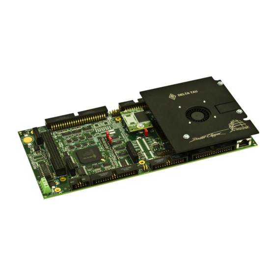
Power PMAC Clipper
Single Source Machine Control
21314 Lassen St. Chatsworth, CA 91311 // Tel. (818) 998-2095 Fax. (818) 998-7807 //
^3Power PMAC Clipper
4-4050xx0-xx0-xxx0xx
^4
April 15, 2016
..............................................................................
DELTA TAU
Data Systems, Inc.
NEW IDEAS IN MOTION ...
Power // Flexibility // Ease of Use
www.deltatau.com
Advertisement
Table of Contents

Related Manuals for Delta Tau Power PMAC Clipper


Summary of Contents for Delta Tau Power PMAC Clipper
- Page 1 User Manual Power PMAC Clipper ^3Power PMAC Clipper 4-4050xx0-xx0-xxx0xx April 15, 2016 DELTA TAU Data Systems, Inc. NEW IDEAS IN MOTION … ……………………………………………..…...………………. Single Source Machine Control Power // Flexibility // Ease of Use 21314 Lassen St. Chatsworth, CA 91311 // Tel. (818) 998-2095 Fax. (818) 998-7807 //...
- Page 2 Copyright Information © 2016 Delta Tau Data Systems, Inc. All rights reserved. This document is furnished for the customers of Delta Tau Data Systems, Inc. Other uses are unauthorized without written permission of Delta Tau Data Systems, Inc. Information contained in this manual may be updated from time-to-time due to product improvements, etc., and may not conform in every respect to former issues.
- Page 3 Power PMAC Clipper User Manual Safety Instructions Qualified personnel must transport, assemble, install, and maintain this equipment. Properly qualified personnel are persons who are familiar with the transport, assembly, installation, and operation of equipment. The qualified personnel must know and observe the following standards and regulations: IEC364resp.CENELEC HD 384 or DIN VDE 0100...
- Page 4 Power PMAC Clipper User Manual REVISION HISTORY REV. DESCRIPTION DATE APPVD Preliminary 10/13/14 Released 07/21/15 Update motor setup 04/15/16...
-
Page 6: Table Of Contents
Power PMAC Clipper User Manual Table of Contents INTRODUCTION ............................9 Documentation .............................. 9 Downloadable Power PMAC Script ......................10 SPECIFICATIONS ........................... 11 Part Number ..............................11 Standard Configuration ..........................11 Options ................................ 12 Accessories ..............................13 Environmental Specifications ........................16 Electrical Specifications .......................... - Page 7 Power PMAC Clipper User Manual Thumbwheel Port Digital Inputs and Outputs ..................51 Configuring Multiplexed I/O on the JTHW port ..................51 J9: General-Purpose Digital Inputs and Outputs (JOPT Port) ..............53 General Purpose I/O (J6) Structures ..................... 54 J10: Handwheel and Pulse/Dir Connector (JHW/PD Port) ................. 56 Handwheel Encoder Software Setup......................
- Page 8 Power PMAC Clipper User Manual J8: Thumbwheel Multiplexer Port (JTHW Port) ..................80 Thumbwheel Port Digital Inputs and Outputs ..................80 Configuring Multiplexed I/O on the JTHW port ..................80 J9: General-Purpose Digital Inputs and Outputs (JOPT Port) ..............81 General Purpose I/O (J6) Structures .....................
-
Page 9: Introduction
Power PMAC Clipper User Manual INTRODUCTION The Power Clipper is a 4 axis motion controller combining the intelligence and capability of a Power PMAC CPU with the convenience and savings of a low cost platform that is 100% hardware compatible with its Turbo PMAC family member the Turbo PMAC Clipper. -
Page 10: Downloadable Power Pmac Script
Power PMAC Clipper User Manual Downloadable Power PMAC Script Some code examples require the user to input specific information pertaining to their system hardware. When user information is required, a commentary ending with –User Input is inserted. Caution This manual contains downloadable code snippets in Power PMAC script. These examples can be copied and pasted into the editor area of the IDE software. -
Page 11: Specifications
Power PMAC Clipper User Manual SPECIFICATIONS Part Number The Power Clipper comes standard with a powerful set of hardware and software capabilities, plus a full set of options and accessories. Standard Configuration The standard configuration of the Power Clipper provides the following features: ... -
Page 12: Options
The “short-pin” version of the right-angle box header connectors. These support flat cable connections to field wiring, but not connections through breakout boards that stack under it (e.g. Delta Tau’s stack breakout board or custom breakout boards). Options The following options can be ordered for the Power Clipper board: CPU Options ... -
Page 13: Accessories
Power PMAC Clipper User Manual Communications Port Options Added Ethernet Port ,1 Gbps, EtherCAT compatible EtherCAT Software License Options (require 2nd Ethernet port option) When the second Ethernet port option is ordered, software license options can also be ordered to support EtherCAT data transfers. - Page 14 Power PMAC Clipper User Manual Power Clipper and the ACC-24S3. The dual-phase DAC outputs support the “sine-wave output” control mode where brushless motor commutation is performed by the Power PMAC. The true-DAC outputs of the ACC-8AS can be used simultaneously with the filtered-PWM analog output on the same channel of the Power Clipper or ACC-24S3 without interference.
- Page 15 Power PMAC Clipper User Manual The serial-encoder inputs on the ACC-84S can be used simultaneously with the serial-encoder input on the same channel of the Power Clipper or ACC-24S3 without interference. Clipper 4-Channel Breakout Board The Clipper 4-Channel Breakout Board can be stacked under the Power Clipper board to provide discrete connectors for each channel and each I/O functionality.
-
Page 16: Environmental Specifications
Power PMAC Clipper User Manual Environmental Specifications Specification Description Range Minimum operating temperature 0°C (32°F) Ambient operating Temperature EN50178 Class 3K3 – IEC721-3-3 Maximum operating temperature 45°C (113°F) Minimum Storage temperature -25°C (-13°F) Storage Temperature Range EN 50178 Class 1K4 – IEC721-3-1/2 Maximum Storage temperature 70°C (158°F) -
Page 17: Electrical Specifications
The +5V and ground reference lines from the power supply should be connected to TB1 terminal block of the Power PMAC Clipper board using 18 AWG stranded wire. The power requirement (± 5%) is: +5 V (20W) @ 3.5 A (Four-channel configuration with a typical load of encoders) +5 V (20W) @ 5.5 A... -
Page 18: Receiving And Unpacking
If the Power PMAC Clipper is to be stored for several weeks before use, be sure that it is stored in a location that conforms to published storage humidity and temperature specifications. -
Page 19: Mounting
Power PMAC Clipper User Manual MOUNTING The location of the Power PMAC Clipper is important. Installation should be in an area that is protected from direct sunlight, corrosives, harmful gases or liquids, dust, metallic particles, and other contaminants. Exposure to these can reduce the operating life and degrade performance of the board. -
Page 20: Physical Specifications
Power PMAC Clipper User Manual Physical Specifications Board Dimensions Rev101 Top View Board Layout Rev101 Top View Mounting are holes shown with screw heads. Mounting... -
Page 21: Connections And Software Setup
Power PMAC Clipper User Manual CONNECTIONS AND SOFTWARE SETUP Installation of electrical equipment is subject to many regulations including national, state, local, and industry guidelines and rules. The following are general recommendations but it is important that the integration be carried out in accordance with all WARNING regulations pertaining to the installation. - Page 22 Power PMAC Clipper User Manual Input Logic Voltage Supplies all PMAC digital circuits +12V Input DAC Supply Voltage Ref to Digital GND -12V Input DAC Supply Voltage Ref to Digital GND For +5V and GND, 18 gauge (AWG) stranded wire is recommended.
-
Page 23: J2: Serial Port
J2: Serial Port This connector allows communicating with Power PMAC Clipper from a host computer through a RS- 232 port. Delta Tau provides the Accessory 3L cable that connects the PMAC to a DB-9 connector. J2 (JRS232) Serial Port Connector... -
Page 24: J3: Machine Connector (Jmach1 Port)
Power PMAC Clipper User Manual J3: Machine Connector (JMACH1 Port) The primary machine interface connector is JMACH1, labeled J3 on the Power PMAC Clipper. It contains the pins for four channels of machine I/O: analog outputs, incremental encoder inputs, amplifier fault and enable signals and power-supply connections. - Page 25 Power PMAC Clipper User Manual CHC4/ Input Encoder C Channel Negative DAC1 Output Analog Output Positive 1 DAC2 Output Analog Output Positive 2 DAC1/ Output Analog Output Negative 1 DAC2/ Output Analog Output Negative 2 AENA1/ Output Amplifier-Enable 1 AENA2/...
- Page 26 Use an encoder cable with high quality shield. Note The standard encoder inputs on the Power PMAC Clipper are designed for differential quadrature type signals. Quadrature encoders provide two digital signals to determine the position of the motor. Each nominally with 50% duty cycle, and nominally 1/4 cycle apart.
-
Page 27: Configuring Quadrature Encoders
Power PMAC Clipper User Manual Differential Quadrature Encoder Wiring for Channel #1 J3(JMACH1) Encoder shield For single-ended encoders, leave the complementary signal pins floating – do not ground them. Alternately, some open collector single ended encoders may require tying the negative pins to ground in series with a 1-2 KOhm resistors. - Page 28 Power PMAC Clipper User Manual The hardware 1/T extension produces 8 bits of fractional data, thus the (1 / 256) 0.00390625 scale factor. Note Channel Quadrature Encoder Number Source Address Clipper[0].Chan[0].ServoCapt.a Clipper[0].Chan[1].ServoCapt.a Clipper[0].Chan[2].ServoCapt.a Clipper[0].Chan[3].ServoCapt.a The top level structure name “Clipper” is an alias for “Gate3”. Either may be used when referring to any “Gate3”...
-
Page 29: Wiring The Dac Output
Power PMAC Clipper User Manual With quadrature encoders, the Power Clipper has the capability of detecting the loss of an encoder signal. This is described in detail in the Encoder Loss Detection section of this manual. Note the distinction between the encoder count error, which reports... - Page 30 Power PMAC Clipper User Manual Connections and Software Setup...
-
Page 31: Amplifier Enable Signal (Aenan/Dirn)
Power PMAC Clipper User Manual Amplifier Enable Signal (AENAn/DIRn) Most amplifiers have an enable/disable input that permits complete shutdown of the amplifier regardless of the voltage of the command signal. PMAC’s AENA line is meant for this purpose. AENA1- is pin 33. -
Page 32: Amplifier Fault Signal (Fault-)
Power PMAC Clipper User Manual Amplifier Fault Signal (FAULT-) This input can take a signal from the amplifier so PMAC knows when the amplifier is having problems, and can shut down action. The polarity is programmable with for motor 1) and the Motor[x].AmpFaultLevel... -
Page 33: Analog Inputs
Power PMAC Clipper User Manual Analog Inputs The Power PMAC Clipper provides four 12-bit analog inputs with a ±10Vdc range. The first two inputs are on JMACH1 pins 45 (ADCIN_1) and 46 (ADCIN_2) referenced to pin 3 (digital ground). Inputs 3 and 4 are on the JMACH3 connector pins 1 (ADCIN_3) and 2 (ADCIN_4). - Page 34 Power PMAC Clipper User Manual The explicit address register(s) can be found by subtracting Sys.piom from (n=0-3). Clipper[0].Chan[0].AdcEnc[n].a Note The ADC input data must be in the “unpacked” format to be read properly; Clipper[0].Chan[0].PackInData = 0 Note Raw ADC Data (in bits) Sys.WpKey = $AAAAAAAA;...
- Page 35 Power PMAC Clipper User Manual The global parameter ADCnVoltsIn reports the ADC data in “user” volts. Where n is the ADC channel number (1 - 4). GLOBAL ADC1VoltsIn = 0; // Voltage input, ADCIN_1 GLOBAL ADC2VoltsIn = 0; // Voltage input, ADCIN_2 GLOBAL ADC3VoltsIn = 0;...
-
Page 36: J4: Machine Connector (Jmach2 Port)
Power PMAC Clipper User Manual J4: Machine Connector (JMACH2 Port) This machine interface connector is labeled JMACH2 or J4 on the Power PMAC Clipper. It contains the pins for four channels of machine I/O: end-of-travel input flags, home flag and pulse-and-direction output signals. -
Page 37: Overtravel Limits And Home Switches
Power PMAC Clipper User Manual PUL_3 Output Pulse Output 3 PUL_4 Output Pulse Output 4 DIR_3 Output Direction Output 3 DIR_4 Output Direction Output 4 EQU3 Output Encoder Comp-Equal 3 EQU4 Output Encoder Comp-Equal 4 B_WDO Output Watchdog Out Indicator/driver... - Page 38 Power PMAC Clipper User Manual Example for Normally Closed Switch J4(JMACH2) USER 4 USER 3 NC NEG. LIMIT 4 NC NEG. LIMIT 3 NC POS. LIMIT 4 NC POS. LIMIT 3 HOME 4 HOME 3 USER 2 USER 1 NC NEG. LIMIT 2 NC NEG.
- Page 39 Power PMAC Clipper User Manual Example for 15-24V Proximity Switch J4(JMACH2) USER 4 USER 3 NC NEG. LIMIT 4 NC NEG. LIMIT 3 NC POS. LIMIT 4 NC POS. LIMIT 3 HOME 4 HOME 3 USER 2 USER 1 NC NEG. LIMIT 2 NC NEG.
-
Page 40: Limits And Flags [Axis 1- 4] Structure Elements
Power PMAC Clipper User Manual While normally closed-to-ground switches are required for the overtravel limits inputs, the home switches could be either normally close or normally open types. The polarity is determined by the home sequence setup, through Note Clipper[i].Chan[j].CaptCtrl... -
Page 41: Step And Direction Pfm Output (To External Stepper Amplifier)
Power PMAC Clipper User Manual Step and Direction PFM Output (To External Stepper Amplifier) The Power PMAC Clipper has the capability of generating step and direction (Pulse Frequency Modulation) output signals to external stepper amplifiers. The step and direction outputs can be connected in single-ended configuration for 5V (input signal) amplifiers. -
Page 42: Compare Equal Outputs
Power PMAC Clipper User Manual Compare Equal Outputs The compare-equals (EQU) outputs have a dedicated use of providing a signal edge when an encoder position reaches a pre-loaded value. This is very useful for scanning and measurement applications. Instructions for use of these outputs are covered in detail in the Power PMAC User Manual. -
Page 43: J7: Machine Connector (Jmach3 Port)
J7: Machine Connector (JMACH3 Port) This machine interface connector is labeled JMACH3 or J7 on the Power PMAC Clipper. It contains the pins for four channels of Gate3 serial encoders and is shared with the T, U, V, and W flags normally used for hall device commutation with the Clipper Drive stack accessory. -
Page 44: Brake Software Setup
Power PMAC Clipper User Manual Brake Software Setup The brake’s output signal has a limited current capability (about 100mA) and should be wired using external relays to the motor. Caution The following settings are required to synchronize the enabling/disabling of the motor with the brake output signal. - Page 45 Power PMAC Clipper User Manual 0: Rising 1: Falling EnDat = 2 SSI = 3 EnDat 0: Phase Typically 0 Encoder 1: Servo (Units of Serial Clock Cycles) Protocol M Divisor N Divisor Trigger Delay Protocol Reserved Bit #: Binary: Hex ($): ...
- Page 46 Power PMAC Clipper User Manual Bit #13 specifies the trigger mode. Typically set to 0 for continuous (on-going position). Bit #12 is the trigger enable bit, must be set to 1 to trigger. Bit #11 specifies whether a Gray to Binary conversion is necessary.
- Page 47 Power PMAC Clipper User Manual Ch. # Serial Encoder Data Registers Clipper[0].Chan[0].SerialEncDataA Clipper[0].Chan[0].SerialEncDataB Clipper[0].Chan[1].SerialEncDataA Clipper[0].Chan[1].SerialEncDataB Clipper[0].Chan[2].SerialEncDataA Clipper[0].Chan[2].SerialEncDataB Clipper[0].Chan[3].SerialEncDataA Clipper[0].Chan[3].SerialEncDataB With a 37-bit (25-bit single-turn, 12-bit multi-turn) serial encoder, the resulting position data would reside in the following bit fields: PowerBrick[].Chan[].SerialEncDataA...
- Page 48 Power PMAC Clipper User Manual EncTable[1].Type = 1; EncTable[1].pEnc = Clipper[0].Chan[0].SerialEncDataA.a; EncTable[1].index1 = 7; // Shift left 7 bits EncTable[1].index2 = 0; // No right shift EncTable[1].index3 = 0; EncTable[1].index4 = 0; EncTable[1].index5 = 0; EncTable[1].index6 = 0; EncTable[1].ScaleFactor = 1 / EXP2(7);...
- Page 49 Power PMAC Clipper User Manual Examples: A 37-bit (25-bit Single-Turn, 12-bit Multi-Turn) serial EnDat rotary encoder is set to $01002500. A 25-bit (25-bit Single-Turn, no Multi-Turn) serial SSI rotary encoder is set to $00002500. A 25-bit serial SSI linear encoder is set to $00002500.
-
Page 50: J8: Thumbwheel Multiplexer Port (Jthw Port)
Power PMAC Clipper User Manual J8: Thumbwheel Multiplexer Port (JTHW Port) Thumbwheel Multiplexer Port on the JTHW connector has 8 inputs and 8 outputs at TTL levels. These may be used as general purpose I/O if the MuxIO feature is not used. . The direction of the input and output lines on this connector are set by jumpers E14 and E15. -
Page 51: Thumbwheel Port Digital Inputs And Outputs
Power PMAC Clipper User Manual The direction of the input and output lines on this connector are set by jumpers E14 and E15. If E14 is removed or E15 is installed then the multiplexing feature of the JTHW port cannot be used. - Page 52 Power PMAC Clipper User Manual Also the direction control and polarity must be at the default settings. Complete instructions for use of this I/O are covered in detail in the Power PMAC User Manual. For the multiplexed digital I/O on ACC-34 boards, the application will access the I/O points through their image words in Power PMAC memory.
-
Page 53: J9: General-Purpose Digital Inputs And Outputs (Jopt Port)
The direction of the input and output lines on this connector are set by jumpers E16 and E17. The 34-pin connector was designed for easy interface to OPTO-22 or equivalent optically isolated I/O modules. Delta Tau's Acc-21F is a six-foot cable for this purpose. -
Page 54: General Purpose I/O (J6) Structures
Power PMAC Clipper User Manual Output Machine Output 3 11, 13 Common PMAC Common Output Machine Output 2 11, 13 Common PMAC Common Output Machine Output 1 11, 13 Common PMAC Common Output +5 Power I/O Common PMAC Common ... - Page 55 Power PMAC Clipper User Manual An M-variable can be assigned to an individual bit of an element, or to a consecutive set of bits. When the assignment is made through the IDE, an application-specific name can be given to the variable. For example: ptr LaserOn->Clipper[0].GpioData[0].21...
-
Page 56: J10: Handwheel And Pulse/Dir Connector (Jhw/Pd Port)
Power PMAC Clipper User Manual J10: Handwheel and Pulse/Dir Connector (JHW/PD Port) JHW/PD port provides two differential Quadrature encoder inputs (HW1 and HW2) and two differential PFM outputs or PWM output pairs. There is no index channel on HW1 and HW2. The Serial encoders on Power Clipper’s channels 1 and 2 are shared with HW1 and HW2 respectively and jumpers E6 and E7... -
Page 57: Handwheel Encoder Software Setup
Power PMAC Clipper User Manual Handwheel Encoder Software Setup To enable the handwheel encoders in software set , (j=1,2). The encoder Clipper[i].Chan[j].SerialEncEna=0 counter is available in . This has 8 bits of 1/T fractional counts. Use Clipper[i].Chan[j].SerialEncDataA to read this location with an . -
Page 58: Handwheel 5Th Motor Using The Option -12 Dac
Power PMAC Clipper User Manual Handwheel 5th motor using the Option -12 DAC Using one of the handwheel encoders and the Option-12 DAC a complete 5 motor can be created with axis flags form the JOPT port: // Typical pointers for encoder count direction PTR CountDirHW1->U.IO:$90005C.11.1... -
Page 59: P2: Usb Device Port
P21: Ethernet Communications Port This connector is used to establish communication over Ethernet between the PC and the Power PMAC Clipper. Delta Tau strongly recommends the use of RJ45 CAT5e or better shielded cable. P17: USB Communications Port The USB “host” port is located next to the Ethernet communication port at P21. It is a “Standard-A”... -
Page 60: Drive - Motor Setup
Power PMAC Clipper User Manual DRIVE - MOTOR SETUP The Power PMAC Clipper supports three types of outputs: Analog ±10V 13-bit Filtered PWM Pulse Frequency Modulation (PFM) Analog ±10V 16-bit True DAC with Acc-8AS The following chart summarizes the steps to implement for setting up a motor properly with the Power... -
Page 61: Filtered Pwm Output (Analog ±10V)
Power PMAC Clipper User Manual Filtered PWM Output (Analog ±10V) In this mode, the ±10V analog output is obtained by passing the digital PWM signal through a low pass 30KHz filter. This technique, although not as high performance as a true digital to analog converter, is more than adequate for most servo applications. -
Page 62: Open Loop Test: Encoder/Decode
Absolute Serial Encoders (EnDat, SSI, BiSS, Yaskawa, Panasonic, Tamagawa, Mitutoyo): The Power PMAC Clipper has no control on the direction sense of the serial data stream (packets). There are no software parameters that allow changing the direction sense of absolute serial encoders. -
Page 63: Position-Loop Pid Gains
Power PMAC Clipper User Manual Some amplifiers allow swapping the DAC+ and DAC- signal to invert the direction travel of the motor. Otherwise, two of the motor leads have to be swapped. If the motor/axis direction does not comply now with the machine design then negative jog commands can be issued for positive motion, and vice versa. -
Page 64: Typical Settings For Four Channels Of Filtered Pwm Setup
Power PMAC Clipper User Manual Typical Settings for Four Channels of Filtered PWM Setup: Sys.WpKey=$AAAAAAAA // Clocks – Phase and Servo Clipper[0].PhaseFreq=10000; // 10KHz Phase Clipper[0].PhaseClockDiv=0; Clipper[0].ServoClockDiv=3; // 2.25KHz Servo Clipper[0].AdcAmpStrobe=$fffffc; Sys.PhaseOverServoPeriod=1/(Clipper[0].ServoClockDiv+1) Sys.ServoPeriod=1000*(Clipper[0].ServoClockDiv+1)/Clipper[0].PhaseFreq // PWM setup Clipper[0].Chan[0].PwmDeadTime=0; Clipper[0].Chan[0].PackOutData=0; Clipper[0].Chan[0].PackInData=0; Clipper[0].Chan[0].PwmFreqMult=5;... - Page 65 Power PMAC Clipper User Manual Motor[2].Servo.Kp=51.702454; Motor[2].Servo.Kvfb=1438.4297; Motor[2].Servo.Ki=0.0099164471; Motor[2].Servo.Kvff=1438.4297; Motor[2].Servo.Kaff=19470.463; Motor[2].Servo.Kvifb=0; Motor[2].Servo.Kviff=0; Motor[2].Servo.Kfff=0; Motor[2].FatalFeLimit=20000; Motor[2].MaxSpeed=2048; Motor[2].InvAmax=20; Motor[2].JogTa=50; Motor[2].JogTs=20; Motor[2].JogSpeed=102.4; Motor[2].Servo.MaxPosErr=100000 //************** Motor3 Motor[3].ServoCtrl=1; Motor[3].pDac=Clipper[0].Chan[2].Pwm[2].a; Motor[3].pEncStatus=Clipper[0].Chan[2].Status.a; Motor[3].pAmpEnable=Clipper[0].Chan[2].OutCtrl.a; Motor[3].pAmpFault=Clipper[0].Chan[2].Status.a; Motor[3].pLimits=Clipper[0].Chan[2].Status.a Motor[3].AmpFaultLevel=1 Motor[3].MaxDac=16384 //< PID & Safety > Motor[3].Servo.Kp=51.702454; Motor[3].Servo.Kvfb=1438.4297; Motor[3].Servo.Ki=0.0099164471; Motor[3].Servo.Kvff=1438.4297; Motor[3].Servo.Kaff=19470.463;...
-
Page 66: Pulse Frequency Modulation Output (Step And Direction)
Power PMAC Clipper User Manual Pulse Frequency Modulation Output (Step and Direction) The Power Clipper has the capability of generating Pulse Frequency Modulation (Step and Direction) output signals for control of external devices such as stepper amplifiers. The maximum pulse frequency and minimum pulse width are typically provided by the third party device manufacturer. -
Page 67: Motor-Specific Setup Elements
Power PMAC Clipper User Manual Encoder Decode Control: Clipper[0].Chan[j].EncCtrl Clipper[0].Chan[j].TimerMode Clipper[0].Chan[j].TimerMode is set to 3 to feed back the internally generated PFM signal to the Clipper[0].Chan[j].TimerA register each servo cycle. This is in units of whole counts, with no fractional- count estimation (low 8 bits always zero). -
Page 68: Typical Settings For Four Channels Of Open Loop Pfm Setup
Power PMAC Clipper User Manual Motor[x].Servo.Kbreak = 0 // Zero gain inside deadband zone If a real feedback sensor is used, the motor’s servo loop will be tuned as a velocity mode servo. This will not be covered here please refer to the Power PMAC User Manual for details of this procedure. - Page 69 Power PMAC Clipper User Manual Motor[4].pAmpEnable=0 //May be stepper drive specific //Encoder Conversion Table EncTable[1].Type = 1 EncTable[1].pEnc = Clipper[0].Chan[0].TimerA.a EncTable[1].index1 = EncTable[1].index2 = 0 EncTable[1].index3 = EncTable[1].MaxDelta = EncTable[1].ScaleFactor = 1/256 Motor[1].pEnc = EncTable[1].a Motor[1].pEnc2 = EncTable[1].a EncTable[2].Type = 1 EncTable[2].pEnc =...
-
Page 70: Acc-24S3 4-Channel Axis Expansion Stack Board
4 additional 12-bit ADCs and 1 filtered-PWM analog output. The setup of the axis expansion is virtually the same as the Power PMAC Clipper base board with the exception that “Clipper[0]” references are replaced with “Clipper[1]”, the activation and addition of new motors (5-8) and pointers and different addresses for the direct addressed ADCs and the ECT setup. - Page 71 Power PMAC Clipper User Manual The JEXPx extensions are inserted on the Power Clipper base board in the folloing locations: The stanoff hardware and the will fit onto the ACC-24S3 as in the following picture (although the JEXPx extenders are placed on the Power Clipper base board as in the above picture:...
-
Page 72: Default Jumper Configurations
Power PMAC Clipper User Manual Default Jumper Configurations The following table shows the default jumper configurations: Jumper Position Description Note Not currently used Not Installed Not currently used Not Installed Not currently used Not Installed Not currently used Not Installed Selection between handwheel input or serial encoder input on Gate3[i].Chan[0].SerialEncDataA... -
Page 73: Tb1 (Jpwr): Power Supply Input
This 4-pin terminal block is used to bring the 5VDC logic power and +/-12VDC DAC supply into the ACC-24S3 and Power PMAC Clipper stack. The power connector on the base board may be used instead but not both simultaneously as this could lead to ground loop wiring. -
Page 74: J3: Machine Connector (Jmach1 Port)
Use the same hardware wiring setup as the base Power PMAC Clipper board. Configuring Quadrature Encoders Use the same software setup as the base Power PMAC Clipper board with the following differences: Gate3 index is 1 (Clipper[1]) ... -
Page 75: Amplifier Enable Signal (Aenan/Dirn)
Use the same hardware wiring setup as the base Power PMAC Clipper board. Setting up the Analog (ADC) Inputs Use the same software setup as the base Power PMAC Clipper board with the following differences: Gate3 index is 1 ... - Page 76 = ((Clipper[1].Chan[0].AdcEnc[3] >> 20) * 10 / 2048) – ADC8ZeroOffset ; CLOSE Using the ADC for Servo Feedback Use the same software setup as the base Power PMAC Clipper board with the following differences: Gate3 index is 1 (Clipper[1]) ...
-
Page 77: J4: Machine Connector (Jmach2 Port)
B_WDO output allows monitoring the state of the Watchdog safety feature. Use the same hardware wiring setup as the base Power PMAC Clipper board. Use the same software setup as the base Power PMAC Clipper board with the following differences: ... -
Page 78: Step And Direction Pfm Output (To External Stepper Amplifier)
This is very useful for scanning and measurement applications. Use the same hardware wiring setup as the base Power PMAC Clipper board. Use the same software setup as the base Power PMAC Clipper board with the following differences: ... -
Page 79: J7: Machine Connector (Jmach3 Port)
ADC inputs and four channels of brake outputs. Use the same hardware wiring setup as the base Power PMAC Clipper board. Brake Software Setup Use the same software setup as the base Power PMAC Clipper board with the following differences: Gate3 index is 1 (Clipper[1]) ... -
Page 80: J8: Thumbwheel Multiplexer Port (Jthw Port)
Thumbwheel Multiplexer Port on the JTHW connector provides 16 general-purpose inputs or outputs at TTL levels. Use the same hardware wiring setup as the base Power PMAC Clipper board. Use the same software setup as the base Power PMAC Clipper board with the following differences: ... -
Page 81: J9: General-Purpose Digital Inputs And Outputs (Jopt Port)
This connector provides 16 general-purpose inputs or outputs at TTL levels. Use the same hardware wiring setup as the base Power PMAC Clipper board. Use the same software setup as the base Power PMAC Clipper board with the following differences: ... -
Page 82: J10: Handwheel And Pulse/Dir Connector (Jhw/Pd Port)
PFM outputs or PWM output pairs. Use the same hardware wiring setup as the base Power PMAC Clipper board. Handwheel Encoder Software Setup Use the same software setup as the base Power PMAC Clipper board with the following differences: Gate3 index is 1 (Clipper[1]) ... -
Page 83: Motor Setup Code
Power PMAC Clipper User Manual Motor Setup Code Typical Settings for Four Channels of Filtered PWM Setup: Sys.WpKey=$AAAAAAAA // Clocks – Phase and Servo Clipper[1].PhaseFreq=10000; // 10KHz Phase Clipper[1].PhaseClockDiv=0; Clipper[1].ServoClockDiv=3; // 2.25KHz Servo Clipper[1].AdcAmpStrobe=$fffffc; Sys.PhaseOverServoPeriod=1/(Clipper[1].ServoClockDiv+1) Sys.ServoPeriod=1000*(Clipper[1].ServoClockDiv+1)/Clipper[1].PhaseFreq // PWM setup Clipper[1].Chan[0].PwmDeadTime=0;... - Page 84 Power PMAC Clipper User Manual Motor[6].AmpFaultLevel=1 Motor[6].MaxDac=16384 //< PID & Safety > Motor[6].Servo.Kp=51.702454; Motor[6].Servo.Kvfb=1438.4297; Motor[6].Servo.Ki=0.0099164471; Motor[6].Servo.Kvff=1438.4297; Motor[6].Servo.Kaff=19470.463; Motor[6].Servo.Kvifb=0; Motor[6].Servo.Kviff=0; Motor[6].Servo.Kfff=0; Motor[6].FatalFeLimit=20000; Motor[6].MaxSpeed=2048; Motor[6].InvAmax=20; Motor[6].JogTa=50; Motor[6].JogTs=20; Motor[6].JogSpeed=102.4; Motor[6].Servo.MaxPosErr=100000 //************** Motor3 Motor[7].ServoCtrl=1; Motor[7].pDac=Clipper[1].Chan[2].Pwm[2].a; Motor[7].pEncStatus=Clipper[1].Chan[2].Status.a; Motor[7].pAmpEnable=Clipper[1].Chan[2].OutCtrl.a; Motor[7].pAmpFault=Clipper[1].Chan[2].Status.a; Motor[7].pLimits=Clipper[1].Chan[2].Status.a Motor[7].AmpFaultLevel=1 Motor[7].MaxDac=16384 //< PID & Safety >...
-
Page 85: Typical Settings For Four Channels Of Open Loop Pfm Setup
Power PMAC Clipper User Manual Motor[8].JogSpeed=102.4; Motor[8].Servo.MaxPosErr=100000 Typical Settings for Four Channels of Open Loop PFM Setup: Sys.WpKey=$AAAAAAAA //Global Clock Settings Clipper[1].PhaseFreq=9035.69; Clipper[1].PhaseClockDiv=0; Clipper[1].ServoClockDiv=3; Clipper[1].AdcAmpStrobe=$fffffc; Clipper[1].PfmClockDiv=5 Clipper[1].EncClockDiv=5 Sys.PhaseOverServoPeriod=1/(Clipper[1].ServoClockDiv+1) Sys.ServoPeriod=1000*(Clipper[1].ServoClockDiv+1)/Clipper[1].PhaseFreq //Channel PFM Hardware Settings Clipper[1].Chan[0].PfmWidth=15 //May be stepper drive specific Clipper[1].Chan[0].OutputMode=8 Clipper[1].Chan[0].PackOutData=0... - Page 86 Power PMAC Clipper User Manual EncTable[5].Type = 1 EncTable[5].pEnc = Clipper[1].Chan[0].TimerA.a EncTable[5].index1 = EncTable[5].index2 = 0 EncTable[5].index3 = EncTable[5].MaxDelta = EncTable[5].ScaleFactor = 1/256 Motor[5].pEnc = EncTable[5].a Motor[5].pEnc2 = EncTable[5].a EncTable[6].Type = 1 EncTable[6].pEnc = Clipper[1].Chan[1].TimerA.a EncTable[6].index1 = EncTable[6].index2 = 0 EncTable[6].index3 =...
Need help?
Do you have a question about the Power PMAC Clipper and is the answer not in the manual?
Questions and answers