
Related Manuals for Delta Tau Power PMAC EtherLite


Summary of Contents for Delta Tau Power PMAC EtherLite
- Page 1 sales@artisantg.com artisantg.com (217) 352-9330 | Visit our website - Click HERE...
-
Page 2: Power Pmac Etherlite
HARDWARE REFERENCE MANUAL Power PMAC EtherLite Power PMAC MACRO/EtherCAT Master PEL3- August 9, 2022 Document # MN-000252... -
Page 3: Copyright Information
© 2022 Delta Tau Data Systems, Inc. All rights reserved. This document is furnished for the customers of Delta Tau Data Systems, Inc. Other uses are unauthorized without written permission of Delta Tau Data Systems, Inc. Information contained in this manual may be updated from time-to-time due to product improvements, etc., and may not conform in... -
Page 4: Safety Instructions
Power PMAC EtherLite Hardware Reference Manual Safety Instructions Qualified personnel must transport, assemble, install, and maintain this equipment. Properly qualified personnel are persons who are familiar with the transport, assembly, installation, and operation of equipment. The qualified personnel must know and observe the following standards and regulations: IEC364resp.CENELEC HD 384 or DIN VDE 0100... - Page 5 Power PMAC EtherLite Hardware Reference Manual Data input and output protection Validate backups and ranges to cope with unintentional modification of input/output data to control systems and equipment. • Checking the scope of data • Checking validity of backups and preparing data for restore in case of falsification and abnormalities •...
- Page 6 Power PMAC EtherLite Hardware Reference Manual REVISION HISTORY REV. DESCRIPTION DATE APPVD Created the manual 12/21/12 DCDP Added the Reliability Predictions Report 2/25/13 DCDP Added UKCA Marking to front cover and added 09/01/21 description in Agency of Approval section Updated UKCA standard...
-
Page 7: Table Of Contents
Power PMAC EtherLite Hardware Reference Manual Table of Contents INTRODUCTION......................... 7 SPECIFICATIONS........................8 Part Number ............................ 8 Environmental Specifications ......................9 Electrical Specifications........................9 Physical Specifications ........................9 Agency Approval and Safety ......................9 RECEIVING AND UNPACKING .................... 10 Unpacking Guidelines ........................10 Use of Equipment ......................... -
Page 8: Introduction
Power PMAC EtherLite Hardware Reference Manual INTRODUCTION The Power PMAC CPU is the most powerful and most flexible controller that Delta Tau presently offers, now integrated into this compact, panel mount format. The Power PMAC UMAC CPU can control up to 256 axes, whether through direct local control, or distributed control over a MACRO fiber optic ring, or over an EtherCAT network. -
Page 9: Specifications
Power PMAC EtherLite Hardware Reference Manual SPECIFICATIONS Part Number Below is a diagram for generating the Power PMAC EtherLite’s part number: The EtherCAT license is programmed in hardware on the MACRO/EtherCAT card inside the EtherLite at the factory and cannot be upgraded in the field. -
Page 10: Environmental Specifications
Power PMAC EtherLite Hardware Reference Manual Environmental Specifications 0°C to 45°C Safe Operating Temperature Safe Storage Temperature -25°C to 70°C Humidity 10% to 95 % non-condensing Electrical Specifications Current Draw at 24VDC for Logic Power 1.0 ± 0.2 Amps Physical Specifications 6.05”... -
Page 11: Receiving And Unpacking
4. If Power PMAC EtherLite is to be stored for several weeks before use, be sure that it is stored in a location that conforms to published storage humidity and temperature specifications stated in this manual. -
Page 12: Mounting
Temperature, humidity and vibration specifications should also be considered. Power PMAC EtherLite can be mounted with a 4-hole panel mount, two U-shape notches on the bottom and two pear-shaped holes on top. Mounting is also identical to this on all peripheral devices. -
Page 13: Macro Setup
Power PMAC EtherLite Hardware Reference Manual MACRO SETUP The procedure used for setting up the EtherLite for controlling MACRO Stations is identical to the procedure used for all MACRO Ring Controllers using Gate3 hardware. Therefore, please refer to the Power PMAC MACRO User Manual for setup instructions. -
Page 14: Ethercat Setup
Power PMAC EtherLite Hardware Reference Manual ETHERCAT SETUP The procedure for setting up a Power PMAC EtherLite to use an EtherCAT ring is identical for all Power PMACs. Therefore, please refer to the EtherCAT Software Setup manual for details on how to set up an EtherCAT ring. -
Page 15: Layout & Pinouts
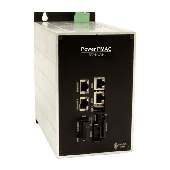
Power PMAC EtherLite Hardware Reference Manual LAYOUT & PINOUTS Layout This layout is for a fully populated EtherLite; that is, one with two EtherCAT Master Ports and with MACRO (RJ45 connections). The external dimensions of the EtherLite do not change, regardless of the options chosen. -
Page 16: Connectors
Power PMAC EtherLite Hardware Reference Manual Connectors Connector Layout The layouts below show Power PMAC EtherLite with video options. Not all EtherLites have this option. RJ45 MACRO Version The connectors are labeled below: Top View Front View +24VDC Logic Power... - Page 17 Power PMAC EtherLite Hardware Reference Manual Fiber Optic MACRO Version The connectors are labeled below: Top View Front View +24VDC Logic Power Connector Ethernet 0 EtherCAT 1 Ethernet 1 EtherCAT 2 Keyboard USB 1 USB 2 Fiber Optic OUT SD Card...
-
Page 18: 24 Vdc Logic Power Input
Power PMAC EtherLite Hardware Reference Manual 24 VDC Logic Power Input Mating Connector Delta Tau Part Number: 016-P00104-08P Phoenix Contact Part Number: 1777303 (Front MSTB 2.5-5.08) Top View Pin # Symbol Function Description Return for 24VDC Logic 24VDC RET Power... -
Page 19: Ethernet Connections
Power PMAC EtherLite Hardware Reference Manual Ethernet Connections The Power PMAC EtherLite provides two Ethernet ports on the front panel: ETH 0 and ETH 1. Both ports can accept standard CAT-5 Ethernet cables with RJ-45 connectors. Both Ethernet ports provide transformer isolation to prevent ground-loop problems. - Page 20 Power PMAC EtherLite Hardware Reference Manual ETH 1 Ethernet Port (P16) The “ETH 1” port is the second-to-top-connector on the front panel. It is the auxiliary Ethernet port and not intended for primary host communications. Its pinout can be seen below:...
-
Page 21: Etherсat Connections
Power PMAC EtherLite Hardware Reference Manual EtherСAT Connections The user can order one to two EtherCAT Master ports, E0 and E1, with the Power PMAC EtherLite. Both ports can accept standard CAT-5 Ethernet cables with RJ-45 connectors. Both EtherCAT ports provide transformer isolation to prevent ground-loop problems. - Page 22 Power PMAC EtherLite Hardware Reference Manual E1 EtherCAT Port (P20) The “E1” port is the second-to-top-connector on the front panel on the far left of the front of the EtherLite. This port can be used to control an additional EtherCAT ring. Its pinout can be seen below:...
-
Page 23: Usb Connections
Power PMAC EtherLite Hardware Reference Manual USB Connections The Power PMAC EtherLite board provides two USB ports on the front panel, one host port and one device port. Both provide USB 2.0 protocol communications. USB ports are not electrically isolated, so care must be taken in the grounding scheme when any separately powered device is connected to one of these ports. - Page 24 Power PMAC EtherLite Hardware Reference Manual USB 2 Device Port (P15) The USB “device” port is labeled “USB 2” on the front panel. It is a “Micro-B” format connector located just below the USB host port. With this port, the Power PMAC CPU board acts as a peripheral device when it is powered off.
-
Page 25: Rs-232 Connection
IDC 10-pin connector, with the pinout arranged such that a flat cable crimped to an IDC 10-pin header at this end and a 9-pin D-sub connector at the other end will provide a standard RS-232 connection. The Delta Tau ACC-3L cable provides this connectivity. MAIN RS232: 10-Pin Receptacle... -
Page 26: Watchdog Timer Connection (Tb1)
Power PMAC EtherLite Hardware Reference Manual Watchdog Timer Connection (TB1) The Power PMAC UMAC CPU board provides a dedicated connector for the output of the on-board watchdog timer. This 3-point removable terminal block is on the bottom edge of the board, near the front end. -
Page 27: Appendix A: Reliability Predictions Report
Power PMAC EtherLite Hardware Reference Manual APPENDIX A: RELIABILITY PREDICTIONS REPORT The following is the Reliability Predictions Report for the “most fully-loaded” version of the Power PMAC EtherLite (i.e. the part number with the most options added possible): RELIABILITY PREDICTIONS REPORT... - Page 28 Mean Time Between Failures (MTBF) Calculations Projected Plan Introduction Purpose The reliability report predictions will be prepared for the Delta Tau products and their associated options. The report will be prepared in accordance with MIL- HDBK-217F Notice 2 with higher than actual stress ratio parameters.
- Page 29 Power PMAC EtherLite Hardware Reference Manual FIGURE 1. RELIABILITY BLOCK DIAGRAM FAILURE RATE FAILURE RATE FAILURE RATE TOTAL OF SUB SYS “A” OF SUB SYS “B” OF SUB SYS “C” FAILURE RATE 1 X 10 = __________________ MTBF TOTAL FAILURE RATE List of Products &...
- Page 30 0.171565 5,828,709 ETHERLITE BACKPLANE To calculate the MTBF number: Not applicable for this product (see Power PMAC EtherLite System in the table above). 1. Enter the first line item from Table 1 on the work sheet provided on page 3.
Need help?
Do you have a question about the Power PMAC EtherLite and is the answer not in the manual?
Questions and answers