Advertisement
Quick Links
IC5, IC6, IC8
®
Ideal components of every Sonnex™, Prodigy
,
or Adagio
®
multiroom audio system, Excite™
speakers by Crestron
®
offer excellent sound
quality and flexible installation in a range of
popular sizes and configurations.
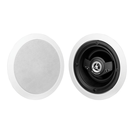
The IC5, IC6, and IC8 round in-ceiling speakers,
sold in pairs, include paint plugs installed on the
front of the speakers, perforated metal grilles,
and a mounting cutout template. The matte white
ABS plastic frame and white metal grille can be
painted to suit any room decor.
1
Installation
Determine Placement In Room
Speaker placement depends on the size
and primary purpose of the room.
For home theater applications, the Excite
in-ceiling speaker line is an excellent
choice for the surround and back chan-
nels.
As indicated in the figure to the right,
suggested placement is at the angles
from the 0° primary viewing/listening
angle.
For applications such as classrooms,
conference rooms, and multi-room audio
distribution installs, other considerations
in speaker placement are ceiling height,
and whether listeners are more likely to
be seated or standing.
The table below and the diagram to the
right help to show proper speaker
spacing for optimum sound coverage.
Ceiling Height / Speaker Spacing
SPEAKER SPACING
CEILING
LISTENER
LISTENER
HEIGHT
SEATED
STANDING
8.0 ft (2.5 m)
9.5 ft (2.9 m)
5.7 ft (1.7 m)
10.0 ft (3.1 m) 13.7 ft (4.2 m)
9.7 ft (3.0 m)
12.0 ft (3.7 m) 17.5 ft (5.3 m) 13.7 ft (4.2 m)
14.0 ft (4.3 m) 21.5 ft (6.6 m) 17.7 ft (1.7 m)
1
For Regulatory Compliance information, refer to the latest
version of Doc. 7147.
QUICKSTART DOC. 7127C (2029453)
Excite™ In-Ceiling Speakers
Prepare Mounting Holes
Before finalizing the speaker locations, check to
make sure there are no fixtures, pipes, air ducts,
joists, or other possible obstructions. Use a good
quality stud finder to locate joists.
If you do not have access to the area above the
ceiling, and you are unable to verify that there are
no obstructions, carefully drill a small hole just
through the ceiling near the middle of the proposed
speaker location(s) and use one of the commer-
cially available inspection devices designed for this
purpose, or do one of the following:
●
Use a piece of stiff wire, bent into an "L"
shape, with one end long enough to explore an
area equal to the size of the speaker with the
toggle clamps extended. Insert the wire into
the hole, make sure it rotates freely in a
complete circle and that there is sufficient
0°
depth, or
●
Use a drywall saw to cut a small hole at a 45°
angle toward the inside of the hole. An angle
cut simplifies repair since the removed piece
90°
90°
can be reinserted to help plug the hole.
110°
110°
Left
Right
135°
135°
Surround
Surround
150°
150°
If there are no obstructions, use the supplied
Left
Right
template to trace outlines of the mounting holes on
Back
Back
the ceiling. Cut the final mounting holes at a 90°
angle to the ceiling.
Spacing
90°
Paint the Speakers/Grilles
Coverage
Coverage
Speaker rim and/or grille painting should be done
Area
Area
Primary
prior to mounting.
Listening
Position
1. Leave the painting plug installed in the front of
the speaker.
2. Carefully remove the material on the underside
of the grille and set it aside for reinstallation. It
may be necessary to use a knife or other
sharp instrument to free an edge of the
material so it can be peeled away. Use care to
avoid cutting the material.
3. Dry brush or lightly spray the surface to be
painted. Use care to avoid clogging the holes
in the grille.
www.crestron.com
Specifications subject to change
05.11
without notice.
Install Cables
Run the cables from the audio source to each speaker
location following all appropriate local codes. Strip the
ends of the speaker cable wires 1/4" to 1/2" (6 mm to
12 mm) and twist the exposed strands.
Mount/Remove Speakers
The in-ceiling speakers include four toggle clamps and four
stabilizing spring clips that simplify the mounting process.
If grilles are mounted on the speakers, remove them
before proceeding. (Refer to "Install/Remove Grilles",
below.)
1. Connect the speaker cable wires to the spring termi-
nals by pressing the top of the terminals down and
inserting the exposed strands into the hole. Make sure
that left and right channels are connected to the left
and right speakers, respectively, and that the + wires
go to the + (red coded) terminals, and the – wires go to
the – (black coded) terminals.
2. With the toggle clamps turned inward, insert the
speaker into the opening; the stabilizing spring clips
will help to hold the speaker in place. As you tighten
the four screws on the front of the speaker, the toggle
clamps will first rotate into clamping position (refer to
45°
the figure to the right) and then begin holding the
speaker to the ceiling. Tighten the screws until the
speaker is secure; do not overtighten.
3. Speaker removal is accomplished by reversing the
procedures given in steps 1 and 2 above.
a. Loosen the front screws to unclamp the speaker.
Continue to loosen the screws until the toggle
clamps rotate inward.
b. When the speaker is loose, carefully reach up into
the opening and press the spring clips inward so
the speaker can be removed from the opening.
c.
Disconnect the wires from the terminals.
Install/Remove Grilles
To install the grille, place it in position and carefully press
until the surface of the grille is flush with the surface of the
outer flange.
To remove the grille, insert a slim, flat-blade screwdriver
between the grille and the outer flange, and carefully pry
the grille up and out.
It may be necessary to press one or more of the mounting
screws and toggle clamps toward the front to push the
grille free of the flange.
888.273.7876
201.767.3400
Rear View (Typical)
Stabilizing
Spring Clips (4)
Spring
Terminals
Toggle
Clamps (4)
Front View (Typical)
Tighten Screws
Advertisement

Subscribe to Our Youtube Channel
Related Manuals for Crestron Excite IC5


Summary of Contents for Crestron Excite IC5
- Page 1 Excite™ Before finalizing the speaker locations, check to Run the cables from the audio source to each speaker Rear View (Typical) speakers by Crestron ® offer excellent sound make sure there are no fixtures, pipes, air ducts, location following all appropriate local codes.
- Page 2 Depth Width Crestron, the Crestron logo, Adagio, Excite, Prodigy and Sonnex are trademarks or registered trademarks of Crestron Electronics, Inc. in the United States and other countries. Other trademarks, registered trademarks, and trade names may be used in this document to refer to either the entities claiming the marks and names or their products.
Need help?
Do you have a question about the Excite IC5 and is the answer not in the manual?
Questions and answers