Sign In
Upload
Download
Table of Contents
Contents
Add to my manuals
Delete from my manuals
Share
URL of this page:
HTML Link:
Bookmark this page
Add
Manual will be automatically added to "My Manuals"
Print this page
×
Bookmark added
×
Added to my manuals
Manuals
Brands
Charlton & Jenrick Manuals
Indoor Fireplace
Polaris 1000
Assembly, installation and operation instructions
Charlton & Jenrick Polaris 1000 Assembly, Installation And Operation Instructions
Led electric fire
Hide thumbs
Also See for Polaris 1000
:
Installation and operation instructions manual
(34 pages)
1
2
Table Of Contents
3
4
5
6
7
8
9
10
11
12
13
14
15
16
17
18
19
20
21
22
23
24
25
26
27
28
29
30
31
32
33
page
of
33
Go
/
33
Contents
Table of Contents
Bookmarks
Table of Contents
Table of Contents
Important Safety Informa on
Technical Specifications
Parts and Hardware
Appliance Dimensions
Installa on Instruc Ons
Opera Ng Instruc Ons
6A. Manual Control Panel
6B. Remote Controls
Temperature Unit
Maintenance
Others
Service Parts List
Warranty
Advertisement
Quick Links
Download this manual
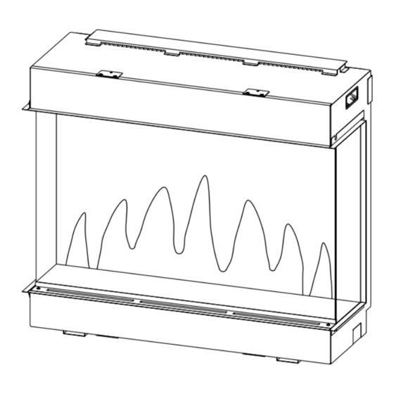
LED Electric Fire
Model: Polaris 840/1000/1600
INSTALLATION AND OPERATION INSTRUCTIONS
Please read the instruc ons carefully before installa on or
use and keep for future reference
Table of
Contents
Previous
Page
Next
Page
1
2
3
4
5
Advertisement
Table of Contents
Need help?
Do you have a question about the Polaris 1000 and is the answer not in the manual?
Ask a question
Questions and answers
Related Manuals for Charlton & Jenrick Polaris 1000
Indoor Fireplace Charlton & Jenrick Polaris 840 Installation And Operation Instructions Manual
Led electric fire (34 pages)
Indoor Fireplace Charlton & Jenrick PARAGON P9 Owner's Manual
Paragon gas fire (32 pages)
Indoor Fireplace Charlton & Jenrick Paragon P3 Owner's Manual
(28 pages)
Indoor Fireplace Charlton & Jenrick PARAGON 2016 Owner's Manual
(28 pages)
Indoor Fireplace Charlton & Jenrick PARAGON 2000 Plus SLIDE CONTROL Owner's Manual
(32 pages)
Indoor Fireplace Charlton & Jenrick PARAGON P5 BF Owner's Manual
(32 pages)
Indoor Fireplace Charlton & Jenrick Paragon Core BF Remote Control Owner's Manual
(32 pages)
Indoor Fireplace Charlton & Jenrick PARAGON P8 Owner's Manual
(56 pages)
Indoor Fireplace Charlton & Jenrick Polaris 1600E Assembly, Installation And Operation Instructions
Led electric fire (33 pages)
Indoor Fireplace Charlton & Jenrick 2000 Plus Extra Remote Owner's Manual
(33 pages)
Indoor Fireplace Charlton & Jenrick PARAGON FOCUS 18 HE Owner's Manual
(32 pages)
Indoor Fireplace Charlton & Jenrick Solstice Operating Manual
(9 pages)
Indoor Fireplace Charlton & Jenrick EF16NC Installation Instructions & Operating Manual
(8 pages)
Indoor Fireplace Charlton & Jenrick Paragon SlimLine 3 Slide Owner's Manual
(32 pages)
Indoor Fireplace Charlton & Jenrick INFINITY 780 BF NG Owner's Manual
(36 pages)
Indoor Fireplace Charlton & Jenrick 480E Installation And Operation Instructions Manual
Led electric fire (33 pages)
This manual is also suitable for:
Polaris 840
Polaris 1600
Polaris 1000e
Polaris 1600e
Table of Contents
Print
Rename the bookmark
Delete bookmark?
Delete from my manuals?
Login
Sign In
OR
Sign in with Facebook
Sign in with Google
Upload manual
Upload from disk
Upload from URL


Need help?
Do you have a question about the Polaris 1000 and is the answer not in the manual?
Questions and answers