Advertisement
Quick Links
Assembly instruction
Sport-Thieme
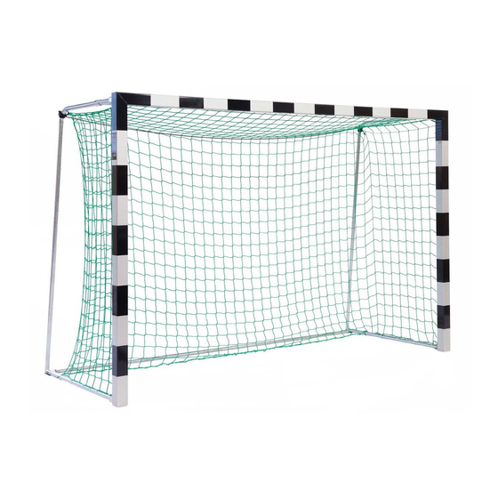
Handball Goal
3x2 m, Free-standing with Fixed Net Brackets
Thanks for choosing Sport-Thieme equipment!
In order to enjoy this product please note the following instructions for safety, use and maintenance before assembly.
®
Cat.-no. 115 0953:
Sport-Thieme®
Handball Goal, 3x2 m,
Free-standing with Fixed
Net Brackets
Cat.-no. 113 6500:
Sport-Thieme®
Handball Goal, 3x2 m,
standing in ground sockets.
With fixed net brackets
D-38367 Grasleben · Germany
sport-thieme.com · info @sport-thieme.com
Phone: +49 53 57 181 543 · Fax: +49 53 57 181 921
Cat.-no.: 115 0953
2392905
239 2918
113 6500
239 2400
239 2413
Advertisement

Related Manuals for Sport-thieme 115 0953


Summary of Contents for Sport-thieme 115 0953
- Page 1 239 2400 239 2413 Handball Goal 3x2 m, Free-standing with Fixed Net Brackets Thanks for choosing Sport-Thieme equipment! In order to enjoy this product please note the following instructions for safety, use and maintenance before assembly. Cat.-no. 115 0953: Sport-Thieme®...
- Page 2 Assembly instruction Cat.-no. 115 0953; 113 6500 1. Scope of delivery Please check the following content before assembly. The following indicated quantities refer to 1 goal. In case of a delivery in pairs we double the amount cor- respondingly. Pictured colours of profiles are only samples and may differ from delivered profiles.
- Page 3 Assembly instruction Cat.-no. 115 0953; 113 6500 Accessories Piece Description Net holder Nut, 40 mm, thread M8 Bush with thread M8, of aluminium round tube 20 x 5 mm, length 40 mm Plastic holder Hexagon socket screw M8 x 20, DIN 7991...
- Page 4 Assembly instruction Cat.-no. 115 0953; 113 6500 2. Assembly of the goal The following tools are necessary: 2 wrench/ring spanners 13 mm 1 mallet/hammer 1 drill Ø 1,5 mm 1 thin screw driver (for net hook fixing if necessary) a) Assembly of crossbar/uprights: Lay crossbar and uprights on the ground, groove facing upwards and mitres joining.
- Page 5 Assembly instruction Cat.-no. 115 0953; 113 6500 Then join upright and crossbar at the external edge and adjust upright and crossbar. Screw 2 hexagon socket screws DIN 7991, M8 x 20 in the external corner and tighten all screws (see picture bottom right).
- Page 6 Assembly instruction Cat.-no. 115 0953; 113 6500 c) Assembly of net hoops at the bottom Screw from upright’s inside 4 hexagon socket screws M8 x 14, DIN 912 in the bottom end of the upright with extended Allen key SW6, length 120 mm. Fix from the outside 4 nuts M8, DIN 934 (see 2nd to 4th bottom pictures). Then adjust net hoops at the top and at the bottom and tighten all screws.
- Page 7 Assembly instruction Cat.-no. 115 0953; 113 6500 d) Assembly of caps Stick caps in the open ends of uprights (see picture bottom left). Bore them with drill 1.5 mm through the holes provided in the uprights. Then fix plug pins with a hammer/mallet (see picture bottom right).
- Page 8 Assembly instruction Cat.-no. 115 0953; 113 6500 Fix ground tube between the net hoops (see 1st picture bottom left). Screw 1 self-locking nut M8, DIN 985 so that the nut out- side is flush with the screw of the bush (see picture bottom right). Then unscrew hexagon screw at the ground tube (see 2st picture bottom left).
- Page 9 Assembly instruction Cat.-no. 115 0953; 113 6500 Fix net with plastic holders in the bottom part of net hoops. Cut off protruding ends of plastic holders (see picture bottom right). b) Fix ends of upper and lower tensioning rope at the mounted ring nuts. Cut off protruding rope ends (see bottom picture).
- Page 10 Assembly instruction Cat.-no. 115 0953; 113 6500 4. Assembly of the ground sockets a) For handball gates with a size of 3,00 x 2,00 m the distance of the ground sockets must be 3,08 m (middle socket – middle socket = center distance).
- Page 11 Assembly instruction Cat.-no. 115 0953; 113 6500...
- Page 12 Assembly instruction Cat.-no. 115 0953; 113 6500...
Need help?
Do you have a question about the 115 0953 and is the answer not in the manual?
Questions and answers