Advertisement
Quick Links
Instruction Sheet
Application
Model
Disassembly
7156161
Motor Replacement Kit
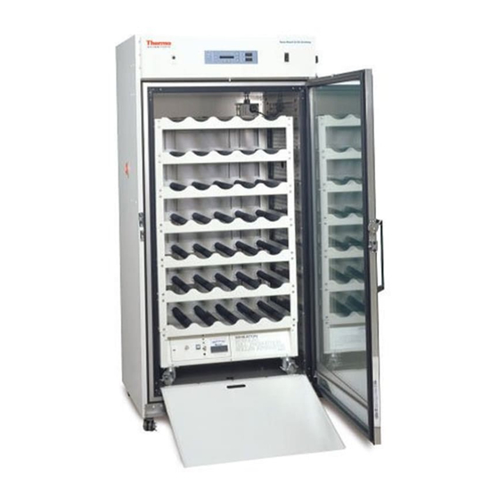
3950/3951, 3960/3961, 3850 Reach-In Incubators
Important service instructions follow. Read and understand the
information before starting this procedure.
Warning Potential electrical hazards. Only qualified persons should
perform the following procedures.
Warning Equipment being serviced must be turned off and disconnected
from the power source to prevent possible injury.
Tools required: Common hand tools
Retain all disassembled parts for re-installation, unless specified otherwise..
1. Move any product inside this unit to another location.
2. Press the unit power switch to the OFF position.
3. Disconnect the power cord at both ends.
4. Allow the unit to cool before servicing.
5. Remove the shelves and shelf channels.
6. Using a #2 Phillips screwdriver, remove the
screws that secure the top duct (Figure 1).
▲
▲
Figure 1. Remove Screws
Advertisement

Related Manuals for Thermo Scientific 3950


Summary of Contents for Thermo Scientific 3950
- Page 1 Instruction Sheet 7156161 Motor Replacement Kit Application 3950/3951, 3960/3961, 3850 Reach-In Incubators Model Important service instructions follow. Read and understand the information before starting this procedure. Warning Potential electrical hazards. Only qualified persons should perform the following procedures. ▲ Warning Equipment being serviced must be turned off and disconnected from the power source to prevent possible injury.
- Page 2 Disassembly (continued) 7. Carefully remove the top duct to expose the blower scroll. See Figure 2. 8. Using a #2 Phillips screwdriver, remove the screws that secure the blower scroll ring (Figure 3). Figure 2. Set Top Duct Aside Figure 3. Remove Ring 9.
- Page 3 Disassembly (continued) 11. Using a #2 Phillips screwdriver, remove the screws that secure the top cover. See Figure 6. 12. Remove the top cover to expose the blower motor. Figure 6. Remove Top Cover Screws 15. Disconnect motor lead terminals from the wiring harness (Figure 7).
-
Page 4: Installation
Figure 12. Install in Order Shown 2. Install 1st Teflon® washer, silicone washer, and 2nd Teflon® washer in that order. Refer to Figure 12. With Models 3950, 3951, and 3850 only, add the nylon washer last. Motor Replacement... - Page 5 Installation (continued) 3. Using an 11/32” hex nut driver, secure the motor mounting plate to the motor assembly with the retained nuts. See Figure 13. 4. Wipe any debris from the motor mounting gasket, and install it onto the motor assembly (Figure 14). Align the clearance holes with the nuts just installed.
- Page 6 9. Connect blower motor P/N 156161 as 115V configuration (Models 3950, 3960, and 3850 only). Note that the wiring Figure 18. Leads to Capacitor diagram is available on the blower motor nameplate. Connect the loose piece terminal to the unused wiring harness white wire as an insulator.
- Page 7 Installation (continued) 12. Insert the motor shaft through the blower wheel. Align the blower wheel set screw with the motor shaft flat side. See Figure 22. 13. Using a 1/8” hex wrench, lightly tighten the set screw that secures the blower wheel to the motor shaft (Figure 23) as the blower wheel will need to be adjusted.
- Page 8 Installation (continued) 16. Install the top duct (Figure 25), carefully aligning the notches in the back (Figure 25). 17. Secure in place with a #2 Phillips screwdriver and the retained screws (Figure 26). Figure 25. Align Back Notches Figure 26. Secure Top Duct 18.
Need help?
Do you have a question about the 3950 and is the answer not in the manual?
Questions and answers