Advertisement
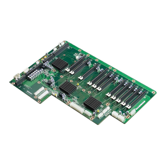
PCE-5B12-00A1E Backplane: 12-slot BP for 20-slot
chassis, 10 PCIe x16, and 1 PCIe x4
Startup Manual
Packing List
Before you begin installing your card, please make sure that
the following items have been shipped:
• PCE-5B12-00A1E startup manual 1st ED
• M4*6*0.7 Round Screws
• 2-year Quality Warranty Card
If any of these items are missing or damaged, please con-
tact your distributor or sales representative immediately.
Specifications
Standard Functions
• PICMG 1.3 slots: PCE-5B12-00A1E supports PCE-5000
and 7000 series CPU boards
• PCIe slots: 10 PCIe x16 and 1 PCIe x4
*If you have any questions about memory, I/O or IRQ
resource limitations, please contact Advantech locally or
FAE for further support.
• PCIe switch: One 5 ports/48 lanes and two 24 ports/96
lane PCIe Gen2 switch reduce data latency
• USB (2.0) ports: 4 Universal Serial Bus ports as pin
headers
Mechanical and Environment
• Dimensions: 327.66 x 417 mm
• Power supply voltage: +12 V, +5 V, -12 V, -5 V, +3.3 V,
5 VSB
• Power requirements: Refer to CPU board, add-on card
& peripheral documentation
• Operating temperature: 0 ~ 60° C (Depending on sys-
tem thermal solution)
• Weight: 1.1 kg (weight of board)
For more information on this and other Advantech
products, please visit our website at:
http://www.advantech.com
http://www.advantech.com/eplatform
For technical support and service, please visit our
support website at:
http://www.advantech.com/support/
This manual is for PCE-5B12-00A1E.
Part No. 20065B1200
Printed in China
The backplane has a number of connectors and jumpers
that allow you to configure your system to suit your ap-
plication. The table below lists the function of each of the
connectors and jumpers.
P/N: 1939000410
P/N: 2190000902
Edition 1,
May 2013
Connectors and Jumpers
Connectors
Part Reference
Function
SHBA1 ~ SHBD1
PICMG 1.3 CPU board slot
PPCIEX4_1
PCIe x4 with PCIe x16 slot
P1PCIEX16_1~5
PCIe x16 slot
P2PCIEX16_1~5
PCIe x16 slot
EATXPWR1
ATX 2.0 24-pin power connector
EATPWR1
AT 12-pin Power connector
ATX 12 V Auxiliary 4-pin power
ATX12V1
connector
ATX 12 V Auxiliary 4-pin power
ATX12V2
connector
EATX12V1
ATX 12 V 8-pin power connector
EATX12V2
ATX 12 V 8-pin power connector
PWR3V1
3.3 V Auxiliary power connector
PWR3V2
3.3 V Auxiliary power connector
ATX 5V & 12V 4-pin power con-
PWR_4P1
nector
VOLT1
Alarm board
FAN1 ~ FAN7
Fan connectors
FANDEC1
Fan speed detect connector
SMBUS1 ~
Chassis sensor board connectors
SMBUS2
JFP1
Power and reset button connector
IPMB1
IPMB connector
USB12
USB connector
USB34
USB connector
ATX feature Connector (5 VSB,
PSON) for Advantech redundant
power supply: 1757001757,
PSON2
1757001760, 1757001758,
1757001761, 1757001759,
1757001677
PCE-5B12-00 Startup Manual 1
Advertisement
Table of Contents

Subscribe to Our Youtube Channel
Related Manuals for Advantech PCE-5B12-00A1E


Summary of Contents for Advantech PCE-5B12-00A1E
- Page 1 P2PCIEX16_1~5 PCIe x16 slot Standard Functions EATXPWR1 ATX 2.0 24-pin power connector • PICMG 1.3 slots: PCE-5B12-00A1E supports PCE-5000 and 7000 series CPU boards EATPWR1 AT 12-pin Power connector • PCIe slots: 10 PCIe x16 and 1 PCIe x4 ATX 12 V Auxiliary 4-pin power...
-
Page 2: Connectors And Jumpers
Connectors and Jumpers Jumpers Part Reference Function ATX/AT mode select connector EATPWR1 PSON1 1-2: AT mode Name 2-3: ATX mode (default) PWROK PCIe generation selection connector for primary switch 1-2: Gen1 JGEN1 2-3: Gen2 (default) 12 V * The PCIe generation setting is -12 V backwards compatible. - Page 3 Connectors and Jumpers 3.3 V JFP1 Name PWRBTN# RESET# VOLT1 Name 5VSB IPMB1 Name IPMB_CLK -5 V IPMB_DAT 3.3 V -12 V USB12 12 V Name USBV0 FAN1 ~ FAN7 USBV0 Name USBD0- USBD1- 12 V USBD0+ FANIO1 ~ FANIO7 USBD1+ FANDEC1 Null...
-
Page 4: Block Diagram
Connectors and Jumpers PSON2 JGEN1 & JGEN2: PCIe Generation Selection Con- nector Name Jumper Setting Function PSON# 2 - 3 closed pins Gen2 (Default) +5 VSB 1 - 2 closed pins PSON1: ATX/AT Mode Selection Gen1 Jumper Setting Function 1 - 2 closed pins SW1: PCIe Gen1 card Compatibility for Non-Compli- AT mode ant Gen1 endpoints... -
Page 5: Locating Jumpers & Connectors
Locating Jumpers & Connectors PPCIEX4_1 P1PCIEX16_ P2PCIEX16_ SMBUS1 FAN1 JTAG1 SMBUS2 USB34 PWR3V1 USB12 IPMB1 EATX12V1 EATX12V2 FANDEC1 PWR1_4P1 VOLT1 JFP1 PSON2 PSON1 EATXPWR1 PWR3V2 FAN3 ATX12V1 ATX12V2 EATPWR1 FAN4 FAN5 FAN6 FAN7 SW 1 Figure 2: Locating Jumpers & Connectors Board Dimensions Figure 3: Board Dimensions PCE-5B12-00 Startup Manual 5...
Need help?
Do you have a question about the PCE-5B12-00A1E and is the answer not in the manual?
Questions and answers