
Related Manuals for Advantech SOM-D580


Summary of Contents for Advantech SOM-D580
- Page 1 User Manual SOM-D580 Intel® Xeon® D-2700 Processor (Ice Lake-D HCC) COM-HPC® Server Size D...
- Page 2 No part of this manual may be reproduced, copied, translated, or transmitted in any form or by any means without the prior written permission of Advantech Co., Ltd. The information provided in this manual is intended to be accurate and reliable.
- Page 3 This product has passed the CE test for environmental specifications when shielded cables are used for external wiring. We recommend the use of shielded cables. This type of cable is available from Advantech. Please contact your local supplier for ordering information.
- Page 4 Document Feedback To assist us with improving this manual, we welcome all comments and constructive criticism. Please send all feedback in writing to support@advantech.com. Packing List Before setting up the system, check that the items listed below are included and in good condition.
- Page 5 COM-HPC Size D Development Board A1 With 25GBASE-KR SOM-DH5000-01A1 OCP card (SOM-EA71) Optional Accessories Part No. Description One-piece heatsink, H.S R4 Intel® Xeon® D HCC 118W 1970005587T001 120x98x23.5 mm 1970005122N001 Add-on fan module, CL R3 160x160 SC for SOM-D580 SOM-D580 User Manual...
- Page 6 In accordance with IEC 704-1:1982 specifications, the sound pressure level at the operator’s position should not exceed 70 dB (A). DISCLAIMER: This set of instructions is given according to IEC 704-1. Advantech dis- claims all responsibility for the accuracy of any statements contained herein.
- Page 7 Serial Presence Detect – refers to serial EEPROM on DRAM that has DRAM Module configuration information Trusted Platform Module - a chip to enhance the security features of a computer system UEFI Unified Extensible Firmware Interface Watchdog Timer SOM-D580 User Manual...
- Page 8 SOM-D580 User Manual viii...
-
Page 9: Table Of Contents
Table 1.8: ..................7 Table 1.9: ..................7 1.3.8 Power Management..............8 1.3.9 Advantech S5 ECO Mode (Deep Sleep Mode)......9 1.3.10 Environmental Specifications............9 1.3.11 MTBF .................... 9 1.3.12 OS Support ................... 9 1.3.13 Advantech iManager ..............10 1.3.14 Power Consumption..............10 Table 1.10:Power Consumption Table (Watts)...... - Page 10 Figure 3.51PkgC SA PS Criteria Power Management Control... 77 Figure 3.52CPU0 PKGC_SA_PS_CRITERIA ......78 Figure 3.53PKGc Interrupt Response Time ....... 79 Figure 3.54ACPI Sx State Control..........80 Figure 3.55Memory Power & Thermal Configuration ....81 Figure 3.56DRAM RAPL Configuration ........82 SOM-D580 User Manual...
- Page 11 Advantech iManager ................131 Appendix A Pin Assignment .......133 SOM-D580 Pin Assignment ..............134 Table A.1: J1 Connector Rows A and B ........134 Table A.2: J1 Connector Rows C and D ........137 Table A.3: J2 Connector Rows E and F........140 Table A.4: J2 Connector Rows G and H........
- Page 12 System Assignments...... 151 System I/O Ports................... 152 Table D.1: System I/O Ports ............ 152 Interrupt Assignments ................153 Table D.2: Interrupt Assignments ..........153 1st MB Memory Map................164 Table D.3: 1st MB Memory Map ..........164 SOM-D580 User Manual...
-
Page 13: Chapter 1 General Information
Chapter General Information This chapter details background information on the SOM-D580 CPU Computer-on-Module. Sections include: Introduction Functional Block Diagram Product Specifications... -
Page 14: Introduction
D580 supports Advantech's ready-to-use Edge AI Suite software toolkit. In terms of memory, SOM-D580 supports either 4 x RDIMM (up to 256GB) or 4 x LRDIMM (up to 512GB). There is additional expansion room for 32 x PCIe Gen 4 and 17 x PCIe Gen 3 lanes. -
Page 15: Functional Block Diagram
Functional Block Diagram Figure 1.1 Block Diagram SOM-D580 User Manual... -
Page 16: Product Specifications
General Purpose SPI Port Power and System Management Rapid Shutdown Thermal Protection System Management Bus GPIO 12/12 FuSa Set of Signals Module Type Pin Support Watchdog Timer Secondary Fan Tach and PWM 28/28 VCC_5V_SBY support VCC_RTC Connector J1 Connector J2 SOM-D580 User Manual... -
Page 17: Processor System
1.3.4 Memory There are a total of 4 memory sockets on SOM-D580. 4 x RDIMM, 1 x DPC, 3200 MT/s, max DIMM capacity 64GB, up to 256GB. 4 x LRDIMM, 1 x DPC, 3200 MT/s, max DIMM capacity 128GB, up to 512GB. -
Page 18: Serial Bus
(but it does not support IDE mode). 1.3.7.3 USB 3.2 / USB 2.0 Supports 4 x USB 3.2 Gen1 (5 Gbps) and 4 x USB 2.0 (480 Mbps). Notice: Advantech strongly recommends using a certified cable to maximize USB 3.2 Gen2 performance. 1.3.7.4 USB 3.2 Gen1 Table 1.6: USB 3.2 Gen1... - Page 19 The standard module has no jumper at SCN2, so BIOS settings are kept without an RTC coin battery. If you need to restore the BIOS to default settings, follow the steps below. Table 1.9: Function N/A [Default] BIOS clear CMOS, load default settings Reserved BIOS Default Settings SOM-D580 User Manual...
-
Page 20: Power Management
Power OK from the main power supply. A high value indicates the power level is good. This signal can be used to postpone module startup allowing carrier-based FPGAs or other configurable devices time to be programmed. 1.3.8.3 Power Sequence According to PICMG COM Express R1.10 specifications. SOM-D580 User Manual... -
Page 21: Advantech S5 Eco Mode (Deep Sleep Mode)
Link: http://com.advantech.com 1.3.12 OS Support The mission of Advantech Embedded Software Services is to "Enhance the quality of life with Advantech platforms and Microsoft Windows Embedded technology." We enable Windows Embedded software products on Advantech platforms to more effectively support the embedded computing community. -
Page 22: Advantech Imanager
The layout checklist will specify the layout constraints and recommendations for trace length, impedance, and other necessary information during design. Please contact your nearest Advantech branch office or call to obtain design docu- ments and further support. SOM-D580 User Manual... -
Page 23: Chapter 2 Mechanical Information
Chapter Mechanical Information This chapter details mechanical information for the SOM-D580 CPU Computer-on-Module. Sections include: Board Information Mechanical Diagrams Assembly Diagrams... -
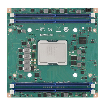
Page 24: Board Information
Board Information The figures below indicate the main chips on the SOM-D580 Computer-on-Module. Please be aware of these positions while designing your own carrier board to avoid mechanical issues and ensure there is sufficient space for thermal solution contact points for best thermal dissipation performance. - Page 25 COM HPC Connector (Primary J2) COM HPC Connector (Primary J1) Figure 2.2 Board Chips ID – Rear SOM-D580 User Manual...
-
Page 26: Mechanical Diagrams
Mechanical Diagrams For more details about 2D/3D models, you can find them on the Advantech COM support service website at http://com.advantech.com. Figure 2.3 Board Mechanical Diagram – Front Figure 2.4 Board Mechanical Diagram – Rear SOM-D580 User Manual... - Page 27 Figure 2.5 Board Mechanical Diagram – Side SOM-D580 User Manual...
-
Page 28: Assembly Diagram
Assembly Diagram These figures demonstrate the assembly order from the thermal module, to the COM module, to the carrier board. Figure 2.6 Assembly Drawing There are 4 reserved screw holes for heat spreader pre-assembly on the SOM-2533. SOM-D580 User Manual... -
Page 29: Assembly Drawings
Mating Angle Requirements: 2.4.1 Allowable Initial Angular Misalignment Figure 2.7 Initial Angular Misalignment 2.4.2 Allowable Final Angular Misalignment Figure 2.8 Final Angular Misalignment SOM-D580 User Manual... -
Page 30: Cpu Package Design
Please consider the CPU and chip height tolerance when designing your thermal solution. Table 2.1: CPU Package Design Item PRE-SMT STACK-UP THICKNESS IHS to MB Height (validated range) 4.217~4.517 mm Figure 2.9 CPU and CPU Socket Height and Tolerance SOM-D580 User Manual... -
Page 31: Chapter 3 Ami Bios
Chapter AMI BIOS This chapter details BIOS setup information for the SOM-D580 CPU Computer-on-Module. Sections include: Introduction Entering Setup Hot/Operation Keys Exit BIOS Setup Utility... - Page 32 Figure 3.1 Setup Program Initial Screen AMI BIOS ROM has a built-in setup program that allows users to modify basic sys- tem configuration. This information is stored in flash ROM so it retains setup informa- tion when the power is turned off. SOM-D580 User Manual...
- Page 33 System Date using the <Arrow> keys. Enter new values through the keyboard. Press the <Tab> key or the <Arrow> keys to move between fields. The date must be entered in MM/DD/YY format. The time must be entered in HH:MM:SS format. SOM-D580 User Manual...
- Page 34 3.2.2 Advanced BIOS Features Setup Select the Advanced tab from the SOM-D580 setup screen to enter the Advanced BIOS Setup screen. Users can select any item in the left frame of the screen, such as CPU Configuration, to go to the sub-menu for that item. Users can display an Advanced BIOS Setup option by highlighting it using the <Arrow>...
- Page 35 Platform Hierarchy Enable or Disable Platform Hierarchy. Storage Hierarchy Enable or Disable Storage Hierarchy. Endorsement Hierarchy Enable or Disable Endorsement Hierarchy. SOM-D580 User Manual...
- Page 36 TPM 2.0 devices. Auto will support both with the default set to TPM 2.0 devices if not found. TPM 1.2 devices will be enumerated. 3.2.2.2 ACPI Settings Figure 3.5 ACPI Settings Enable ACPI Auto Configuration Enables or Disables BIOS ACPI Auto Configuration. SOM-D580 User Manual...
- Page 37 Monitor hardware status. Sequence Adjusting Delay the startup time. Sequence Adjusting Save into Flash Save the Sequence Adjusting setting into Flash. Time Timing for the delay can be adjusted within the range of 0 to 10000ms. SOM-D580 User Manual...
- Page 38 3.2.2.4 Serial Port 1 Configuration Figure 3.7 Serial Port 1 Configuration Serial Port Enable or Disable Serial Port (COM). Change Settings Select optimal settings for a Super IO Device. SOM-D580 User Manual...
- Page 39 3.2.2.5 Serial Port 2 Configuration Figure 3.8 Serial Port 2 Configuration Serial Port Enable or Disable Serial Port (COM). Change Settings Select optimal settings for a Super IO Device. SOM-D580 User Manual...
- Page 40 3.2.2.6 Hardware Monitor Figure 3.9 Hardware Monitor Monitor hardware status. SOM-D580 User Manual...
- Page 41 Console Redirection EMS Enable or Disable Console Redirection. Console Redirection Settings The settings specify how the host computer (which the user is using) will exchange data. Both computers should have the same or compatible settings. SOM-D580 User Manual...
- Page 42 1 stop bit. Flow Control Flow control can prevent data loss from buffer overflow. When sending data, if the receiving buffers are full, a ‘stop’ signal can be sent to stop the data flow. SOM-D580 User Manual...
- Page 43 Enables or Disables 64-bit capable devices to be decoded in Above 4G Address Space (Only if the system supports 64-bit PCI decoding). SR-IOV Support If the system has SR-IOV capable PCIe Devices, this option Enables or Dis- ables Single Root IO Virtualization Support. SOM-D580 User Manual...
- Page 44 BIOS to select the value. ASPM Support Set the ASPM Level: Force L0s – Force all links to L0s State. Auto- BIOS auto configure. Disable- Disable ASPM. Extended Synch If Enabled, it allows generation of Extended Synchronization patterns. SOM-D580 User Manual...
- Page 45 Extended Functions in an ARI Device immediately below the Port. Default value: Disabled. Atomic0p Requester Enable If supported by hardware and set to ‘Enabled’, this function initiates Atomic0p requests only if the Bus Master Enable bit is in the Command Register Set. SOM-D580 User Manual...
- Page 46 Hardware Autonomous Speed If supported by hardware and set to ‘Disabled’, this will disable the hardware’s ability to change link speed except speed rate reduction for the purpose of cor- recting unstable link operation. SOM-D580 User Manual...
- Page 47 AMI Virtual HDisk0 1.00 Mass storage device emulation type. ‘AUTO’ enumerates devices according to their media format. Optical drives are emulated as ‘CDROM’ drives with no media emulated according to drive type. SOM-D580 User Manual...
- Page 48 Mass storage device emulation type. ‘AUTO’ enumerates devices according to their media format. Optical drives are emulated as ‘CDROM’ drives with no media emulated according to drive type. 3.2.2.13 Network Stack Configuration Figure 3.16 PCI Network Stack Configuration Network Stack Enable/Disable UEFI Network Stack. SOM-D580 User Manual...
- Page 49 Figure 3.17 NVMe Configuration Network Stack Enable/Disable UEFI Network Stack. IPv4 PXE Support IPv4 HTTP Support IPv6 PXE Support IPv6 HTTP Support PXE boot wait time Media detect count SOM-D580 User Manual...
- Page 50 Controls the execution of UEFI and Legacy Video OpROM. Other Devices Determines OpROM execution policy for devices other than Network, Storage, or Video. On Board Display Controller Onboard Device has: UEFI [X] Legacy [X] Embedded ROM(s). VIDx1A03; DIDx2000;Class:3/0/0 @Sx0|Bx3|Dx0|Fx0 t:2Sx0|Bx2|Dx0|Fx0 t:2Sx0|Bx0|Dx14|Fx0 t: 1Sx0|Bx3|Dx0|Fx0 SOM-D580 User Manual...
- Page 51 Onboard Device has: UEFI [X] Legacy [X] Embedded ROM(s). VIDx1A03; DIDx188D;Class:2/0/0 @Sx0|Bx89|Dx0|Fx2 t:2Sx0|Bx88|Dx4|Fx0 t: 1Sx0|Bx88|Dx0|Fx0 As1Name:CPK2 SMBIOS: Intel CPK2 On Board Network Controller Onboard Device has: UEFI [X] Legacy [X] Embedded ROM(s). VIDx1A03; DIDx188D;Class:2/0/0 @Sx0|Bx89|Dx0|Fx3 t:2Sx0|Bx88|Dx4|Fx0 t: 1Sx0|Bx88|Dx0|Fx0 SOM-D580 User Manual...
- Page 52 Enable or Disable option ROM execution for selected slot. Slot # 51 Empty Enable or Disable option ROM execution for selected slot. Slot # 61 Empty Enable or Disable option ROM execution for selected slot. SOM-D580 User Manual...
- Page 53 3.2.2.16 Tls Auth Configuration Figure 3.19 Tls Auth Configuration Server CA Configuration Press <Enter> to configure Server CA. Client Cert Configuration Press <Enter> to configure Client Cert. SOM-D580 User Manual...
- Page 54 3.2.2.17 Enroll Cert Figure 3.20 Enroll Cert Enroll Cert Press <Enter> to enroll cert. Delete Cert Press <Enter> to delete cert. SOM-D580 User Manual...
- Page 55 Figure 3.21 Enroll Cert Using File Enroll Cert Using File Enroll Cert Using File. Cert GUID Input digit characters in 11111111-2222-3333-4444-1234567890ab format. Commit Changes and Exit Commit Changes and Exit. Discard Changes and Exit Discard Changes and Exit. SOM-D580 User Manual...
- Page 56 3.2.2.19 Emulation Configuration Figure 3.22 Emulation Configuration uBIOS Generation Enable/Disable uBIOS Generation. Hybrid SLE Mode Enable/Disable Hybrid Level Emulation Mode. MSR Trace for PM Enable/Disable MSR Trace for Power management in uBIOS. SOM-D580 User Manual...
- Page 57 3.2.2.20 Intel® Ethernet Connection Figure 3.23 Port Option Configuration Port Option Configuration SOM-D580 User Manual...
- Page 58 Configure the port option of the device. The Option string is defined as follows: Option 0: 4x25G Option 1: 2x4x10G Option 2: 4x10G Option 3: -4 x1G Option 4: 2x25G Option 5: -4x10G Option 6: 1x100G SOM-D580 User Manual...
- Page 59 3.2.2.22 Chipset Figure 3.25 Chipset Socket Configuration Displays and provides the option to change socket settings. Platform Configuration Press <Enter> to select the Platform System Setup options. SOM-D580 User Manual...
- Page 60 IIO Configuration Displays and provides the option to change IIO Settings. Advanced Power Management Configuration Displays and provides the option to change Power Management Settings. Memory Topology Displays memory topology with Dimm population information. SOM-D580 User Manual...
- Page 61 This should be enabled in order to boot legacy 0S that cannot support CPUs with extended CPUID functions. Hardware Prefetcher = MLC Streamer Prefetcher (MSR 1A4h Bit[0]). Adjacent Cache Prefetch = MLC Spatial Prefetcher (MSR 1A4h Bit[1]). SOM-D580 User Manual...
- Page 62 Legacy PECI agent in trust bit Enable. SMBus Agent SMBus PECI agent in trust bit Enable. IE Agent IE PECI agent in trust bit Enable. Generic Agent Generic PECI agent in trust bit Enable. SOM-D580 User Manual...
- Page 63 Enable – MSR 3Ah and CSR 80h will be locked. Power Good reset is needed to remove lock bits. PKG CST CONFIG CONTROL MSR LOCK Enable – MSR E2h will be locked. Power Good reset is needed to remove lock bits. PPIN Control Unlock and Enable/Disable PPIN Control. SOM-D580 User Manual...
- Page 64 Limit CPU physical address to 46 bits to support older Hyper-V. If enabled, it automatically disables TME-MT. PSMI Configuration PSMI Configuration. Processor Dfx Configuration Displays and provides the option to change Processor Dfx Settings. SOM-D580 User Manual...
- Page 65 3.2.2.25 Pre-Socket Configuration Figure 3.30 CPU Socket 0 Configuration CPU Socket 0 Configuration SOM-D580 User Manual...
- Page 66 CPU Socket 0 Configuration Figure 3.31 CPU Socket 0 Configuration Core Disable Bitmap (Hex) 0: Enable all cores. FFFFFFFFFFF: Disable all cores. Note: At least one core per CPU must be enabled. Disabling all cores is an invalid configuration. SOM-D580 User Manual...
- Page 67 3.2.2.27 PSMI Configuration Figure 3.32 Global PSMI Global PSMI Enable Global PSMI Enable. Socket 0 Configuration SOM-D580 User Manual...
- Page 68 3.2.2.28 Socket 0 Configuration Figure 3.33 Socket 0 Configuration PSMI Enable PSMI Enable. SOM-D580 User Manual...
- Page 69 Triggers MCHECK with MSR 0x72, support for Simics. Mock that system HW is not SGX capable Mock that system HW is not SGX capable: allows to test suppress in the BIOS menu. SGX APB Support FPE on APB. SOM-D580 User Manual...
- Page 70 Enable/Disable PCIe low latency retimers. Skip PCIe retimers detection Skip PCIe retimers detection to speed up the boot. Retimers are present only in specific HW configurations. PCI-E Completion Timeout Configure PCIe Completion Timeout in the Device Control2 register. SOM-D580 User Manual...
- Page 71 Applies to root ports only. Enable MSI/INTx interrupt on fatal errors. TraceHub Configuration Menu TraceHub Configuration Settings. R-Link Settings related to PCI Express Ports (0/1A/1B/1C/1D/2A/2B/2C/2D/3A/3B/3C/ 3D/4A/4B/4C/4D/5A/5B/5C/5D). Port 1A Settings related to PCI Express Ports (0/1A/1B/1C/1D/2A/2B/2C/2D/3A/3B/3C/ 3D/4A/4B/4C/4D/5A/5B/5C/5D). SOM-D580 User Manual...
- Page 72 Figure 3.37 Trace Hub Configuration North Trace Hub Enable Mode Select ‘Host Debugger’ if Trace Hub is used with the host debugger tool or ‘Tar- get Debugger’ if Trace Hub is used by the target debugger software. SOM-D580 User Manual...
- Page 73 This option can disable ASPM support in a PCIe root port. ‘AUTO’ keeps the hardware default. PCI-E Port L1 Exit Latency The length of time this port requires to complete transition from L1 to L0. BUS0 DEVx FUN0 OFF 0x5A bit 0, where X is 0-3. SOM-D580 User Manual...
- Page 74 ECRC Generation Enable/Disable ECRC Generation (Error Capabilities and Control Register). 3.2.2.34 R-Link Figure 3.39 Chipset ECRC Check Enable/Disable ECRC Check (Error Capabilities and Control Register). SERRE Enable/Disable SERRE (SERR Reporting Enable). MCTP Enable/Disable MCTP. SOM-D580 User Manual...
- Page 75 Configure Max Payload Size Supported in the PCIe Capabilities register. ‘AUTO’ keeps the hardware default. PCI-E Port D-state Set to D0 for normal operation, D3Hot to be in the low-power state. PCI-E Completion Timeout SOM-D580 User Manual...
- Page 76 Enable/Disable Compliance Mode for this PCIe port. EOI. Dev 0,2,3 MISCCTRLSTS (Reg 0x188) Bit 26. Figure 3.41 Port 1A Unsupported Request Controls the reporting of unsupported requests that IIO itself detects on requests its receives from a PCI Express/DMI port. SOM-D580 User Manual...
- Page 77 [EMBAR2SZ] Used to set the prefetchable Embar2 size on secondary side of NTB. Value range <12…51> representing BAR sizes <4KB…128PB>. Hide Port? The user can force hide this root port from the OS. MCTP Enable/Disable MCTP. SOM-D580 User Manual...
- Page 78 Configure Max Payload Size Supported in the PCIe Capabilities register. ‘AUTO’ keeps the hardware default. PCI-E Port D-state Set to D0 for normal operation, D3Hot to be in a low-power state. PCI-E Completion Timeout SOM-D580 User Manual...
- Page 79 Enable/Disable Compliance Mode for this PCIe port. Dev 0,2,3 MISCCTRLSTS (Reg 0x188) Bit 26. Figure 3.43 Port 2A Unsupported Request Controls the reporting of unsupported requests that IIO itself detects on requests it receives from a PCI Express/DMI port. SOM-D580 User Manual...
- Page 80 [EMBAR2SZ] Used to set the prefetchable Embar2 size on secondary side of NTB. Value range <12…51> representing BAR sizes <4KB…128PB>. Hide Port? The user can force hide this root port from the OS. MCTP Enable/Disable MCTP. SOM-D580 User Manual...
- Page 81 DMI Port MPSS Configure Max Payload Size Supported in the PCIe Capabilities register. ‘AUTO’ keeps the hardware default. PCI-E Port D-state Set to D0 for normal operation, D3Hot to be in low-power state. PCI-E Completion Timeout SOM-D580 User Manual...
- Page 82 Enable/Disable Compliance Mode for this PCIe port. Dev 0,2,3 MISCCTRLSTS (Reg 0x188) Bit 26. Figure 3.45 Port 2C Unsupported Request Controls the reporting of unsupported requests that IIO itself detects on requests it receives from a PCI Express/DMI port. SOM-D580 User Manual...
- Page 83 [EMBAR2SZ] Used to set the prefetchable Embar2 size on secondary side of NTB. Value range <12…51> representing BAR sizes <4KB…128PB>. Hide Port? The user can force hide this root port from the OS. MCTP Enable/Disable MCTP. SOM-D580 User Manual...
- Page 84 Translation Blocking When set, the component blocks all upstream Memory Requests whose Address Translation (AT) field is not set to the default value. P2P Request Redirect This bit determines when the component redirects peer-to-peer Requests upstream. SOM-D580 User Manual...
- Page 85 When set, the component forwards upstream any Request or Completion TLPs it receives that were redirected upstream by a component lower in the hierarchy. 3.2.2.36 Intel® VMD technology Figure 3.47 Intel® VMD technology Intel® VMD for Volume Management Device on Socket 0 SOM-D580 User Manual...
- Page 86 Figure 3.48 VMD Config VMD Config for PCH Ports Enable/Disable VMD in the stack. VMD Config for IOU 0 Enable/Disable VMD in the stack. VMD Config for IOU 4 Enable/Disable VMD in the stack. SOM-D580 User Manual...
- Page 87 Program WRITE_PKGC_SA_PS_CRITERIA Sub Menu. PkgC SA PS Criteria Power Management Control Program WRITE_PKGC_SA_PS_CRITERIA Sub Menu. MDLL Off Enable shutdown of MDLL during SR. PKGc Interrupt Response Time Programmable Package C-state interrupt response time setup control. SOM-D580 User Manual...
- Page 88 3.2.2.39 Latency Tolerance Requirement (LTR) Figure 3.50 Latency Tolerance Requirement PCIe LTR Override Control Allow manual overrides for PCIE_ILTR_0VRD. SOM-D580 User Manual...
- Page 89 3.2.2.40 PkgC SA PS Criteria Power Management Control Figure 3.51 PkgC SA PS Criteria Power Management Control CPU0 PKGC_SA_PS_CRITERIA Socket-Specific PKGC_SA_PS_CRITERIA. SOM-D580 User Manual...
- Page 90 3.2.2.41 CPU0 PKGC_SA_PS_CRITERIA Figure 3.52 CPU0 PKGC_SA_PS_CRITERIA CPU0 Logical_ip_type WRITE_PKGC_SA_PS_CRITERIA Command [19:12] Logical_ip_type oh:KTI; 1H: RINK 10h-17h: MCDDR0, 1… 18h-1Fh: HBM0, 1… 20h-27h: IIO0, 1… 33h: MDFS PKGC_CRITERIA KTI Enable: B2P WRITE_PKGC_SA_PS_CRITERIA accepts input value. SOM-D580 User Manual...
- Page 91 This field qualifies the validity of the Value field in this register. VALID: This field qualifies the validity of the Value field in this register. VALID: This field qualifies the validity of the Value field in this register. SOM-D580 User Manual...
- Page 92 3.2.2.43 ACPI Sx State Control Figure 3.54 ACPI Sx State Control ACPI S3 Controls ACPI S3 State. ACPI S4 Controls ACPI S4 State. SOM-D580 User Manual...
- Page 93 MEMHOT Output Throttling Mode Options Configure MEMHOT Output Mode options: Enable/Disable the Throt Output high, mid and low bit fields. Memory Power Savings Advanced Options Advanced Settings for CKE and related Memory Power Savings Features. SOM-D580 User Manual...
- Page 94 Override BW_LIMIT_TF Allows custom tuning of BW_LIMIT_TF when DRAM RAPL is enabled. DRAM RAPL Enable\Disable DRAM Rapl. DRAM RAPL Extended Range Select DRAM RAPL Extended Range. CMS ENABLE DRAM PM CMS ENABLE DRAM PM. SOM-D580 User Manual...
- Page 95 Memtrip to thermtrip tree. OFF PKG MEM TO MEMTRIP If set to 0, the processor will ignore offpkg memtrip to memtrip tree. If set to 1, the processor will include offpkg memtrip to memtrip tree. SOM-D580 User Manual...
- Page 96 Memory Power & Thermal Configuration Figure 3.58 Memory Power & Thermal Configuration CKE Throttling Configures CKE Throttling. SREF Feature Select the manual or auto programming Self Refresh feature. PKGC SREF EN Enable/Disable PKGC Self Refresh. SOM-D580 User Manual...
- Page 97 Figure 3.59 PCH-IO Configuration PCI Express Configuration PCI Express Configuration settings. Fia Mux Configuration Configuration of FIA Mux. SOM-D580 User Manual...
- Page 98 PCI Express Root Port Settings. PCI Express Root Port 3 PCI Express Root Port Settings. PCI Express Root Port 4 PCI Express Root Port Settings. PCI Express Root Port 5 PCI Express Root Port Settings. SOM-D580 User Manual...
- Page 99 PCI Express Active State Power Management settings. L1 Substates PCI Express L1 Substates settings. Hot Plug PCI Express Hot Plug Enable/Disable. PCIe Speed Configure PCIe Speed. Auto is equal to Gen2 or Gen3 depending on DTR soft strap. SOM-D580 User Manual...
- Page 100 PCI Express Active State Power Management settings. L1 Substates PCI Express L1 Substates settings. Hot Plug PCI Express Hot Plug Enable/Disable. PCIe Speed Configure PCIe Speed Auto is equal to Gen2 or Gen3 depending on DTR soft strap. SOM-D580 User Manual...
- Page 101 PCI Express Active State Power Management settings. L1 Substates PCI Express L1 Substates settings. Hot Plug PCI Express Hot Plug Enable/Disable. PCIe Speed Configure PCIe Speed Auto is equal to Gen2 or Gen3 depending on DTR soft strap. SOM-D580 User Manual...
- Page 102 PCI Express Active State Power Management settings. L1 Substates PCI Express L1 Substates settings. Hot Plug PCI Express Hot Plug Enable/Disable. PCIe Speed Configure PCIe Speed Auto is equal to Gen2 or Gen3 depending on DTR soft strap. SOM-D580 User Manual...
- Page 103 PCI Express Active State Power Management settings. L1 Substates PCI Express L1 Substates settings. Hot Plug PCI Express Hot Plug Enable/Disable. PCIe Speed Configure PCIe Speed. Auto is equal to Gen2 or Gen3 depending on DTR soft strap. SOM-D580 User Manual...
- Page 104 PCI Express Active State Power Management settings. L1 Substates PCI Express L1 Substates settings. Hot Plug PCI Express Hot Plug Enable/Disable. PCIe Speed Configure PCIe Speed Auto is equal to Gen2 or Gen3 depending on DTR soft strap. SOM-D580 User Manual...
- Page 105 PCI Express Active State Power Management settings. L1 Substates PCI Express L1 Substates settings. Hot Plug PCI Express Hot Plug Enable/Disable. PCIe Speed Configure PCIe Speed Auto is equal to Gen2 or Gen3 depending on DTR soft strap. SOM-D580 User Manual...
- Page 106 PCI Express Active State Power Management settings. L1 Substates PCI Express L1 Substates settings. Hot Plug PCI Express Hot Plug Enable/Disable. PCIe Speed Configure PCIe Speed. Auto is equal to Gen2 or Gen3 depending on DTR soft strap. SOM-D580 User Manual...
- Page 107 PCI Express Active State Power Management settings. L1 Substates PCI Express L1 Substates settings. Hot Plug PCI Express Hot Plug Enable/Disable. PCIe Speed Configure PCIe Speed Auto is equal to Gen2 or Gen3 depending on DTR soft strap. SOM-D580 User Manual...
- Page 108 PCI Express Active State Power Management settings. L1 Substates PCI Express L1 Substates settings. Hot Plug PCI Express Hot Plug Enable/Disable. PCIe Speed Configure PCIe Speed Auto is equal to Gen2 or Gen3 depending on DTR soft strap. SOM-D580 User Manual...
- Page 109 PCI Express Active State Power Management settings. L1 Substates PCI Express L1 Substates settings. Hot Plug PCI Express Hot Plug Enable/Disable. PCIe Speed Configure PCIe Speed Auto is equal to Gen2 or Gen3 depending on DTR soft strap. SOM-D580 User Manual...
- Page 110 PCI Express Active State Power Management settings. L1 Substates PCI Express L1 Substates settings. Hot Plug PCI Express Hot Plug Enable/Disable. PCIe Speed Configure PCIe Speed Auto is equal to Gen2 or Gen3 depending on DTR soft strap. SOM-D580 User Manual...
- Page 111 Pcie 0 Bifurcation Allow changing PCIE bifurcation. Pcie 1 Bifurcation Allow changing PCIE bifurcation. Pcie 2 Bifurcation Allow changing PCIE bifurcation. FIA Mux Configuration Override By Enabling this you override the platform configuration on FIA/WM. SOM-D580 User Manual...
- Page 112 SOM-D580 User Manual...
- Page 113 SOM-D580 User Manual...
- Page 114 Figure 3.74 SATA Configuration Controller SATA Configuration SATA Controller 3 Device Options Settings. SOM-D580 User Manual...
- Page 115 Indicates the maximum speed the SATA controller can support. Aggressive LPM Support Enable PCH to aggressively enter link power state. Port 0 Enable or Disable SATA Port. DH5000 Mapping:SATA1. Port 1 Enable or Disable SATA Port. DH5000 Mapping:SATA2. SOM-D580 User Manual...
- Page 116 Figure 3.76 USB Configuration USB Port Disable Override Selectively Enable/Disable the corresponding USB port from reporting a Device Connection to the controller. SOM-D580 User Manual...
- Page 117 USB devices plugged into the connector will not be detected by the BIOS or USB HS Physical Connector #1 Enable/Disable this USB Physical Connector (physical port). Once disabled, any USB devices plugged into the connector will not be detected by the BIOS or SOM-D580 User Manual...
- Page 118 USB devices plugged into the connector will not be detected by the BIOS or Figure 3.78 Security Configuration BIOS Lock Enable/Disable the PCH BIOS Lock Enable feature. It is required to be enabled to ensure SMM protection of flash. SOM-D580 User Manual...
- Page 119 The feature helps collect crash data from PMC SSRAM. CrashLog On All Reset Option to invoke CrashLog collection on all reset. Shutdown Suppression Configures Shutdown Suppression and Log MCA IERR Support. eMCA Settings Press <Enter> to view or change the eMCA configuration. SOM-D580 User Manual...
- Page 120 EMCA CMCI-SMI Threshold Set the threshold of correctable error for signaling CMCI-CSMI. CSMI Dynamic Disable [Enable] - BIOS disables CSMI when the error threshold is reached. EMCA MCE-SMI Enable Enable/Disable EMCA Uncorrected SMI for gen2. SOM-D580 User Manual...
- Page 121 Figure 3.81 Whea Settings WHEA Support Enable/Disable WHEA support. Whea Log Memory Error Enable/Disable Whea Log Memory Error. Whea Log Processor Error Enable/Disable Whea Log Processor Error. Whea Log PCI Error Enable/Disable Whea Log PCI Error. SOM-D580 User Manual...
- Page 122 Figure 3.82 Error Injection Settings WHEA Error Injection Support Enable/Disable WHEA Error Injection Support. SOM-D580 User Manual...
- Page 123 Figure 3.83 Memory Error Enabling Memory Error Enable/Disable Memory Error. Memory Corrected Error Enable/Disable Memory Corrected Error. Spare Interrupt Spare Interrupt Selection. SOM-D580 User Manual...
- Page 124 IIO IRP0 protocol qt overflow underflow error Enable/Disable IIO Coherent Interface protocol queue table overflow or under- flow error reporting. IIO IRP0 protocol rcvd unexprsp Enable/Disable IIO Coherent Interface protocol layer received unexpected response or completion error reporting. SOM-D580 User Manual...
- Page 125 Enable/Disable IIO Misc. Error. IIO Vtd Error Enable/Disable IIO Vtd Error. Figure 3.85 IIO Error Enabling IIO Dma Error Enable/Disable IIO Dma Error. IIO Dmi Error Enable/Disable IIO Dmi Error. PCIE Error Enable/Disable PCIE Error. SOM-D580 User Manual...
- Page 126 Enable & escalate fatal errors to error pins. PCIE Corrected Error Threshold Counter Enable/Disable PCIE Corrected Error Counter. PCIe Corrected Error Limit Check Enable/Disable the feature to disable reporting PCIe corrected errors for a device if they exceed a given limit. SOM-D580 User Manual...
- Page 127 Set the error threshold for Gen1 and Gen2 speeds. An event is triggered when the error count exceeds the threshold. Error Threshold (Gen3/4) Set the error threshold for Gen3 and Gen4 speeds. An event is triggered when the error count exceeds the threshold. SOM-D580 User Manual...
- Page 128 Gen3 speeds. When an event is triggered, 8GT/s and higher modes are dis- abled. Gen4 Link Degradation Enable/Disable Gen4 link degradation. This applies only when operating at Gen4 speeds. When an event is triggered, 16GT/s and higher modes are dis- abled. SOM-D580 User Manual...
- Page 129 Figure 3.88 Error Control Setting Latch First Corrected Error in KTI Enable/Disable latch first corrected error in KTI. Patrol Scrub Error Reporting Patrol Scrub Error type selection. SOM-D580 User Manual...
- Page 130 Logs the report returned by the BMC self test command. BMC network configuration Configure BMC network parameters. View System Event Log Press <Enter> to view the System Event Log Records. BMC Warm Reset Press <Enter> to do a BMC Warm Reset. SOM-D580 User Manual...
- Page 131 When SEL is Full Choose options for reactions to a full SEL. Log EFI Status Codes Disable the logging of EFI Status Codes or log only the error code, only the progress code, or both. SOM-D580 User Manual...
- Page 132 Erase Log Erase Log Options. When log is full Select the action to be taken when the log is full. SOM-D580 User Manual...
- Page 133 Select to configure LAN channel parameters statically or dynamically (by BIOS or BMC). The Unspecified option will not modify any BMC network parameters during the BIOS phase. VLAN Support Enable VLAN Support to specify the 802.1q VLAN ID. SOM-D580 User Manual...
- Page 134 01/01/12 00:17:58 System Event HEX: 0B 00 02 36 A6 FF 4E 01 00 04 12 00 6F 05 00 FF Generator ID: BIOS (Channel #0) Sensor Number: 0x00 Unspecified Event Description: TimeStamp Clock Synch. Record Type-0x02. Assertion Event. SOM-D580 User Manual...
- Page 135 3.2.3 Security Chipset Figure 3.90 Security Chipset Administrator Password Set Administrator Password. User Password Set User Password. Secure Boot Secure Boot Configuration. SOM-D580 User Manual...
- Page 136 SOM-D580 User Manual...
- Page 137 System is in User mode. The mode change requires a plat- form reset. Secure Boot Mode Secure Boot mode options: Standard or Custom. In Custom mode, Secure Boot Policy variables can be configured by a physi- cally present user without full authentication. SOM-D580 User Manual...
- Page 138 Number of seconds to wait for the setup activation key. 65535(0xFFFF) means indefinite waiting. Bootup NumLock State Select the keyboard NumLock state. Quiet Boot Enables/Disables the Quiet Boot option. Boot Option #1 Sets the system boot order. SOM-D580 User Manual...
- Page 139 Restore/Load Default values for all the setup options. Save as User Defaults Save the changes done so far as User Defaults. Restore User Defaults Restore the User Defaults to all the setup options. UEFI: Built-in EFI Shell SOM-D580 User Manual...
- Page 140 3.2.5 MEBx Login Intel® ME Password MEBx Login. SOM-D580 User Manual...
- Page 141 Chapter S/W Introduction & Installation S/W Introduction Driver Installation Advantech iManager...
- Page 142 S/W Introduction The mission of Advantech Embedded Software Services is to “Enhance quality of life with Advantech platforms and Microsoft Windows embedded technology.” We enable Windows Embedded software products on Advantech platforms to more effectively support the embedded computing community. Customers are freed from the hassle of dealing with multiple vendors (hardware suppliers, system integrators, embedded OS distributors) for projects.
- Page 143 For more details on how to use the APIs and utilities, please refer to the Advantech iManager 2.0 Soft- ware API User Manual.
- Page 144 SOM-D580 User Manual...
- Page 145 Appendix Pin Assignment This appendix details information about the hardware pin assign- ments of the SOM-D580 CPU Com- puter-on-Module. Sections include: SOM-D580 Client Size Pin Assignment...
- Page 146 SOM-D580 Pin Assignment This section gives SOM-D580 pin assignments on the COM HPC connector, which are compliant with COM-HPC Revision 1.10 Client Type pin-out definitions. For more details about how to use these pins and to obtain a design reference, please contact Advantech for a design guide, checklist, reference schematic, and other hardware/ software support.
- Page 147 J1.A62 PCIe08_TX- J1.B62 PCIe08_RX+ J1.A63 PCIe08_TX+ J1.B63 J1.A64 J1.B64 PCIe09_RX- J1.A65 PCIe09_TX- J1.B65 PCIe09_RX+ J1.A66 PCIe09_TX+ J1.B66 J1.A67 J1.B67 PCIe10_RX- J1.A68 PCIe010_TX- J1.B68 PCIe10_RX+ J1.A69 PCIe010_TX+ J1.B69 J1.A70 J1.B70 PCIe11_RX- J1.A71 PCIe11_TX- J1.B71 PCIe11_RX+ J1.A72 PCIe11_TX+ J1.B72 SOM-D580 User Manual...
- Page 148 J1.A92 GPIO_04 J1.B92 IPMB_DAT J1.A93 GPIO_05 J1.B93 GP_SPI_MOSI J1.A94 GPIO_06 J1.B94 GP_SPI_MISO J1.A95 GPIO_07 J1.B95 GP_SPI_CS0# J1.A96 GPIO_08 J1.B96 GP_SPI_CS1# J1.A97 GPIO_09 J1.B97 GP_SPI_CS2# J1.A98 GPIO_10 J1.B98 GP_SPI_CS3# J1.A99 GPIO_11 J1.B99 GP_SPI_CLK J1.A100 TYPE0 J1.B100 GP_SPI_ALERT# NC SOM-D580 User Manual...
- Page 149 J1.C33 USB3_SSRX+ J1.D33 J1.C34 J1.D34 USB2_SSTX- J1.C35 USB2_SSRX- J1.D35 USB2_SSTX+ J1.C36 USB2_SSRX+ J1.D36 J1.C37 J1.D37 USB1_SSTX0- J1.C38 USB1_SSRX0- J1.D38 USB1_SSTX0+ J1.C39 USB1_SSRX0+ J1.D39 J1.C40 J1.D40 USB1_SSTX1- J1.C41 USB1_SSRX1- J1.D41 USB1_SSTX1+ J1.C42 USB1_SSRX1+ NC J1.D42 J1.C43 J1.D43 USB0_SSTX0- SOM-D580 User Manual...
- Page 150 J1.D76 PCIe05_TX- J1.C77 PCIe05_RX- J1.D77 PCIe05_TX+ J1.C78 PCIe05_RX+ J1.D78 J1.C79 J1.D79 PCIe06_TX- J1.C80 PCIe06_RX- J1.D80 PCIe06_TX+ J1.C81 PCIe06_RX+ J1.D81 J1.C82 J1.D82 PCIe07_TX- J1.C83 PCIe07_RX- J1.D83 PCIe07_TX+ J1.C84 PCIe07_RX+ J1.D84 J1.C85 J1.D85 NBASET0_MDI0- NBASET0_M- J1.C86 SMB_CLK J1.D86 DI0+ SOM-D580 User Manual...
- Page 151 DI2+ J1.C93 I2C0_CLK J1.D93 J1.C94 I2C0_DAT J1.D94 NBASET0_MDI3- NBASET0_M- J1.C95 I2C0_ALERT# J1.D95 DI3+ J1.C96 I2C1_CLK J1.D96 NBA- J1.C97 I2C1_DAT J1.D97 SET0_LINK_- MAX# NBA- J1.C98 NBASET0_SDP J1.D98 SET0_LINK_MID NBA- NBASET0_C- J1.C99 J1.D99 SET0_LINK_ACT TREF J1.C100 TYPE1 J1.D100 TYPE2 SOM-D580 User Manual...
- Page 152 J2.E27 PCIe34_TX- J2.F27 PCIe34_RX+ J2.E28 PCIe34_TX+ J2.F28 J2.E29 J2.F29 PCIe35_RX- J2.E30 PCIe35_TX- J2.F30 PCIe35_RX+ J2.E31 PCIe35_TX+ J2.F31 J2.E32 J2.F32 PCIe36_RX- J2.E33 PCIe36_TX- J2.F33 PCIe36_RX+ J2.E34 PCIe36_TX+ J2.F34 J2.E35 J2.F35 PCIe37_RX- J2.E36 PCIe37_TX- J2.F36 PCIe37_RX+ J2.E37 PCIe37_TX+ J2.F37 SOM-D580 User Manual...
- Page 153 J2.E74 J2.F74 PCIe50_RX- J2.E75 PCIe50_TX- J2.F75 PCIe50_RX+ J2.E76 PCIe50_TX+ J2.F76 J2.E77 J2.F77 PCIe51_RX- J2.E78 PCIe51_TX- J2.F78 PCIe51_RX+ J2.E79 PCIe51_TX+ J2.F79 J2.E80 J2.F80 PCIe52_RX- J2.E81 PCIe52_TX- J2.F81 PCIe52_RX+ J2.E82 PCIe52_TX+ J2.F82 J2.E83 J2.F83 PCIe53_RX- J2.E84 PCIe53_TX- J2.F84 PCIe53_RX+ SOM-D580 User Manual...
- Page 154 CLK1- PCIe_REF- J2.E94 J2.F94 CLK1+ PCIe_- J2.E95 J2.F95 CLKREQ3# PCIe_- ETH0- J2.E96 J2.F96 CLKREQ1# 3_PRSNT# PCIe_- ETH0- J2.E97 J2.F97 CLKREQ2# 3_PHY_RST# PCIe_- J2.E98 CLKREQ_OUT0 J2.F98 ETH0_SDP PCIe_- J2.E99 CLKREQ_OUT1 J2.F99 ETH1_SDP PCIe_PER- PCIe_PER- J2.E100 J2.F100 ST_IN0# ST_IN1# SOM-D580 User Manual...
- Page 155 J2.G35 GND J2.H35 PCIe45_TX- J2.G36 PCIe45_RX- J2.H36 PCIe45_TX+ J2.G37 PCIe45_RX+ J2.H37 J2.G38 GND J2.H38 PCIe46_TX- J2.G39 PCIe46_RX- J2.H39 PCIe46_TX+ J2.G40 PCIe46_RX+ J2.H40 J2.G41 GND J2.H41 PCIe47_TX- J2.G42 PCIe47_RX- J2.H42 PCIe47_TX+ J2.G43 PCIe47_RX+ J2.H43 J2.G44 GND J2.H44 PCIe24_TX- SOM-D580 User Manual...
- Page 156 J2.G81 PCIe60_RX- J2.H81 PCIe60_TX+ J2.G82 PCIe60_RX+ J2.H82 J2.G83 J2.H83 PCIe61_TX- J2.G84 PCIe61_RX- J2.H84 PCIe61_TX+ J2.G85 PCIe61_RX+ J2.H85 J2.G86 J2.H86 PCIe62_TX- J2.G87 PCIe62_RX- J2.H87 PCIe62_TX+ J2.G88 PCIe62_RX+ J2.H88 J2.G89 J2.H89 PCIe63_TX- J2.G90 PCIe63_RX- J2.H90 PCIe63_TX+ J2.G91 PCIe63_RX+ J2.H91 SOM-D580 User Manual...
- Page 157 D18 can be an optional pin reserved for DDI1_CTRLDATA. Please contact FAE for details. D63 can be an optional pin reserved for DDI2_CTRLCLK. Please contact FAE for details. D64 can be an optional pin reserved for DDI2_CTRLDATA. Please contact FAE for details. SOM-D580 User Manual...
- Page 158 SOM-D580 User Manual...
- Page 159 Appendix Watchdog Timer This appendix details information about watchdog timer program- ming on the SOM-D580 CPU Com- puter-on-Module. Sections include: Watchdog Timer Programming...
- Page 160 BIOS, and then sets it to EC. Only Win8.1 and Win10 support this. On other OS, it will still use the IRQ number from the BIOS setting as usual. For details, please refer to the iManager & Software API User Manual. SOM-D580 User Manual...
- Page 161 Appendix Programming GPIO This Appendix details illustration of the General Purpose Input and Output pin settings. Sections include: GPIO Register...
- Page 162 H/W Pin Name BIT0 GPI0 BIT1 GPI1 BIT2 GPI2 BIT3 GPI3 BIT4 GPI4 BIT5 GPI5 BIT6 GPI6 BIT7 GPI7 BIT8 GPI8 BIT9 GPI9 BIT10 GPI10 BIT11 GPI11 For details, please refer to the iManager and Software API User Manual. SOM-D580 User Manual...
- Page 163 Appendix System Assignments This appendix gives you informa- tion about system resource allo- cation on the SOM-D580 CPU Computer-on-Module. Sections include: System I/O Ports Interrupt Assignments 1 MB Memory Map...
- Page 164 Motherboard resources 0x000002A0-0x000002BF Motherboard resources 0x000002A0-0x000002BF Motherboard resources 0x000002C0-0x000002DF Motherboard resources 0x000002F0-0x000002F7 Motherboard resources 0x000002F8-0x000002FF Communications Port (COM2) 0x00000300-0x0000037F Motherboard resources 0x000003F8-0x000003FF Communications Port (COM1) 0x00000400-0x0000041F Motherboard resources 0x000004D0-0x000004D1 Programmable interrupt controller 0x00000500-0x000005FE Motherboard resources 0x00000500-0x000005FE Motherboard resources SOM-D580 User Manual...
- Page 165 Microsoft ACPI-Compliant System IRQ 115 Microsoft ACPI-Compliant System IRQ 116 Microsoft ACPI-Compliant System IRQ 117 Microsoft ACPI-Compliant System IRQ 118 Microsoft ACPI-Compliant System IRQ 119 Microsoft ACPI-Compliant System IRQ 120 Microsoft ACPI-Compliant System IRQ 121 Microsoft ACPI-Compliant System SOM-D580 User Manual...
- Page 166 CDF HSUART - 18D8 (COM3) IRQ 16 ASPEED Graphics Family (WDDM) IRQ 160 Microsoft ACPI-Compliant System IRQ 161 Microsoft ACPI-Compliant System IRQ 162 Microsoft ACPI-Compliant System IRQ 163 Microsoft ACPI-Compliant System IRQ 164 Microsoft ACPI-Compliant System IRQ 165 Microsoft ACPI-Compliant System SOM-D580 User Manual...
- Page 167 IRQ 204 Microsoft ACPI-Compliant System IRQ 21 CDF GPIO Controller - 3001 IRQ 256 Microsoft ACPI-Compliant System IRQ 257 Microsoft ACPI-Compliant System IRQ 258 Microsoft ACPI-Compliant System IRQ 259 Microsoft ACPI-Compliant System IRQ 260 Microsoft ACPI-Compliant System SOM-D580 User Manual...
- Page 168 Communications Port (COM2) IRQ 300 Microsoft ACPI-Compliant System IRQ 301 Microsoft ACPI-Compliant System IRQ 302 Microsoft ACPI-Compliant System IRQ 303 Microsoft ACPI-Compliant System IRQ 304 Microsoft ACPI-Compliant System IRQ 305 Microsoft ACPI-Compliant System IRQ 306 Microsoft ACPI-Compliant System SOM-D580 User Manual...
- Page 169 Microsoft ACPI-Compliant System IRQ 347 Microsoft ACPI-Compliant System IRQ 348 Microsoft ACPI-Compliant System IRQ 349 Microsoft ACPI-Compliant System IRQ 350 Microsoft ACPI-Compliant System IRQ 351 Microsoft ACPI-Compliant System IRQ 352 Microsoft ACPI-Compliant System IRQ 353 Microsoft ACPI-Compliant System SOM-D580 User Manual...
- Page 170 Microsoft ACPI-Compliant System IRQ 394 Microsoft ACPI-Compliant System IRQ 395 Microsoft ACPI-Compliant System IRQ 396 Microsoft ACPI-Compliant System IRQ 397 Microsoft ACPI-Compliant System IRQ 398 Microsoft ACPI-Compliant System IRQ 399 Microsoft ACPI-Compliant System IRQ 4 Communications Port (COM1) SOM-D580 User Manual...
- Page 171 Intel® Ethernet Controller (3) I225-IT IRQ 4294967258 Intel® Ethernet Controller (3) I225-IT IRQ 4294967259 Intel® Ethernet Controller (3) I225-IT IRQ 4294967260 Intel® Ethernet Controller (3) I225-IT IRQ 4294967261 Intel® Ethernet Controller (3) I225-IT IRQ 4294967262 Intel® Ethernet Controller (3) I225-IT SOM-D580 User Manual...
- Page 172 Microsoft ACPI-Compliant System IRQ 438 Microsoft ACPI-Compliant System IRQ 439 Microsoft ACPI-Compliant System IRQ 440 Microsoft ACPI-Compliant System IRQ 441 Microsoft ACPI-Compliant System IRQ 442 Microsoft ACPI-Compliant System IRQ 443 Microsoft ACPI-Compliant System IRQ 444 Microsoft ACPI-Compliant System SOM-D580 User Manual...
- Page 173 Microsoft ACPI-Compliant System IRQ 485 Microsoft ACPI-Compliant System IRQ 486 Microsoft ACPI-Compliant System IRQ 487 Microsoft ACPI-Compliant System IRQ 488 Microsoft ACPI-Compliant System IRQ 489 Microsoft ACPI-Compliant System IRQ 490 Microsoft ACPI-Compliant System IRQ 491 Microsoft ACPI-Compliant System SOM-D580 User Manual...
- Page 174 Microsoft ACPI-Compliant System IRQ 71 Microsoft ACPI-Compliant System IRQ 72 Microsoft ACPI-Compliant System IRQ 73 Microsoft ACPI-Compliant System IRQ 74 Microsoft ACPI-Compliant System IRQ 75 Microsoft ACPI-Compliant System IRQ 76 Microsoft ACPI-Compliant System IRQ 77 Microsoft ACPI-Compliant System SOM-D580 User Manual...
- Page 175 Microsoft ACPI-Compliant System IRQ 93 Microsoft ACPI-Compliant System IRQ 94 Microsoft ACPI-Compliant System IRQ 95 Microsoft ACPI-Compliant System IRQ 96 Microsoft ACPI-Compliant System IRQ 97 Microsoft ACPI-Compliant System IRQ 98 Microsoft ACPI-Compliant System IRQ 99 Microsoft ACPI-Compliant System SOM-D580 User Manual...
- Page 176 PCI Express Root Complex 0xFE200000-0xFE7FFFFF Motherboard resources 0xFEC00000-0xFECFFFFF Advanced programmable interrupt controller 0xFED00000-0xFED003FF High-precision event timer 0xFF000000-0xFFFFFFFF Motherboard resources 0xFF000000-0xFFFFFFFF Motherboard resources 0xFFA00000-0xFFA1FFFF CDF PCIeRP[9] - 18AE 0xFFA20000-0xFFA3FFFF CDF PCIeRP[8] - 18AD 0xFFA40000-0xFFA5FFFF CDF PCIeRP[7] - 18AB SOM-D580 User Manual...
- Page 177 Table D.3: 1st MB Memory Map 0xFFA80000-0xFFA8FFFF Intel® USB 3.0 eXtensible Host Controller - 1.0 (Microsoft) 0xFFAB7000-0xFFAB7FFF CDF ME:HECI#3 - 18D6 0xFFAB8000-0xFFAB8FFF CDF ME:HECI#1 - 18D3 SOM-D580 User Manual...
- Page 178 No part of this publication may be reproduced in any form or by any means, such as electronically, by photocopying, recording, or otherwise, without prior written permission from the publisher. All brand and product names are trademarks or registered trademarks of their respective companies. © Advantech Co., Ltd. 2024...
Need help?
Do you have a question about the SOM-D580 and is the answer not in the manual?
Questions and answers