
Related Manuals for Advantech SKY-642


Summary of Contents for Advantech SKY-642
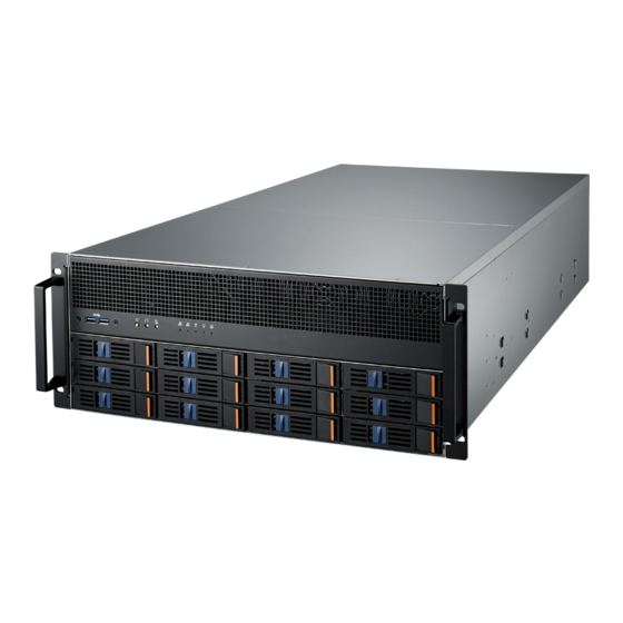
- Page 1 User Manual SKY-642 4U Rackmount Intel® Xeon® Scalable Series GPU Server, Supporting 10 x PCIe x16 Double-Deck Cards Plus 1 x PCIe x16 and 1 x PCIe x8 Single- Deck Cards...
- Page 2 No part of this manual may be reproduced, copied, translated or transmitted in any form or by any means without the prior written permission of Advantech Co., Ltd. Information provided in this manual is intended to be accurate and reliable. How- ever, Advantech Co., Ltd.
- Page 3 Whether your new Advantech equipment is destined for the labo- ratory or the factory floor, you can be assured that your product will provide the reliability and ease of operation for which the name Advantech has come to be known.
- Page 4 You must become familiar with the safety information in this guide before you install, operate, or service Advantech products. Machine Room Environment ...
- Page 5 Advantech, your authorized Advantech partner, or their agents. Equipment Modifications Do not make mechanical modifications to the system. Advantech is not respon- sible for the regulatory compliance of Advantech equipment that has been mod- ified. Equipment Repairs and Servicing ...
- Page 6 Xeon Gold 6136 CPU @ 3.00 Intel 150W GHz/24.75M/12Cores Xeon Gold 6140/2.3GHz/ Intel 140W 24.75M/18Cores Xeon Gold 6142/2.60 GHz/22M/ Intel 150W 16Cores Xeon Gold 6142M/2.6GHz/22M/ Intel 150W 16Cores Xeon Platinum 8158/24.75M/ Intel 150W 12cores Xeon Platinum 8160M/33M/ Intel 150W 24cores SKY-642 User Manual...
- Page 7 3.5" HDD 10TB A10TE MG07AC Toshiba 3.5" HDD 14TB A14TE TS128G Transcend 2.5" SSD 720 SSD720 SQF-S25M8-64G- Advantech 2.5" SSD 64GB Flash 64GB Heatsink I-Skylake-EP S-165W 1960081155N101 CoolJag Heatsink 107.75x78.0x25.5-SC Power 96PSRM- 1600W CRPS Module supply A1K6WCRP SKY-642 User Manual...
- Page 8 MSASH-1 MINI-SAS 1M at top side Cable RAID card M cable SAS 36P/SAS 36P 1700025065-01 Advantech cable out 85cm at rear side Intel XXV710-DA2 Intel XXV710-DA1 Intel XL710-QDA2 LAN Card Intel XL710-QA2 96NIC-1G2P-PE-IN3 Intel I350-T2 SKY-642 User Manual viii...
- Page 9 It should be free of marks and scratches and in perfect working order upon receipt. When unpacking the SKY-642, check it for signs of ship- ping damage. (For example, damaged box, scratches, dents, etc.) If it is damaged or it fails to meet the specifications, notify our service department or local sales repre- sentative immediately.
- Page 10 SKY-642 User Manual...
-
Page 11: Table Of Contents
3.2.5 Server Management ..............63 3.2.6 Security ..................67 3.2.7 Boot..................... 67 3.2.8 Save & Exit ................. 68 Chapter Chipset Software Installation Utility Before You Begin ..................70 Introduction ..................... 70 Windows OS Driver Setup ..............71 SKY-642 User Manual... - Page 12 PCIE SLOT7 ................... 85 Appendix C OEM Command for BMC IPMI tool . 87 Advantech OEM Commands ..............88 C.1.1 BMC Lock/Unclock Command............ 88 C.1.2 SYS LED Control Command ............88 C.1.3 GPU Power Brake Command............. 89 SKY-642 User Manual...
-
Page 13: Chapter 1 Overview
Chapter Overview... -
Page 14: Introduction
High reliability and outstanding performance makes SKY-642 the ideal platform for industrial server applications. SKY-642 uses the Intel C622 chipset and offers a variety of features such as 12 x SATA/SAS hot swappable bays, SAS optional by RAID card, Intel RSTe (Rapid Stor- age Technology Enterprise), RAID 0, 1, 5, 10 (Windows only*), 1 x 2280 connector (B + M Key) for OS installation and cache, 7 x USB 3.0 (4 x in rear, 1 x internal Type A... -
Page 15: System Specifications
1000 W @ 100 ~ 127 V 1600 W @ 200 ~ 240 V Power Connector Expansion 10 x CPU-8P 12V power connector for expansion card. Card power Cable optional, depends on the expansion card type. Expansion Slots SKY-642 User Manual... - Page 16 RoHS Compliant Operating Temperature: 0 to 35° C Non-operating Temperature: -40 to 60° C Environmental Spec. Operating Relative Humidity: 95% @ 40° C (non-condensing) Non-operating Relative Humidity: 95% @ 60° C (non-condens- ing) SKY-642 User Manual...
-
Page 17: System Layout, Led, Jumpers And Connectors
Connectors on the SKY-642 are linked to external devices such as hard disk drives. In addition, SKY-642 has a jumper that are used to clean CMOS for BIOS. The tables below list the functions of each jumper and connector. Later sections in this chapter give instructions for setting jumpers. -
Page 18: Led Definitions
No driver present or power disconnected No activity Driver present Access activity Blinking HDD fail* Identify (locate the HDD)* 4 Hz Blinking 4 Hz SATA/SAS RAID rebuild* 1 Hz Blinking Hot-spare* * Fail, Identify, Rebuild, Hot-spare only work under RAID mode. SKY-642 User Manual... -
Page 19: Jumpers
Green Power supply DC output ON and OK No AC power to all power modules 1.4.2 Jumpers Label Function Default JCMOS1 CMOS clear JME1 ME update Keep CMOS data / Disable ME update Clear CMOS data / Enable ME update SKY-642 User Manual... -
Page 20: Connectors
BP P1 ~ P3 5V power output connector for HDD back plane LAN3_USB1_2, USB3_4 USB port 1, 2, 3, 4 (rear USB3.0) USB7 USB port 7 (internal type-A, horizontal) USB5_6 USB port 5, 6 (front panel USB3.0) SKY-642 User Manual... -
Page 21: Block Diagram
10 * FAN Conn. SPI SKT System Memory SKY-642 has 24 x 288-pin memory slots for DDR4 2133/2400/2666 MHz memory modules/ Intel Optane DC Persistent Memory with maximum capacity of 6TB (Maxi- mum 64 GB for each DIMM). SKY-642 supports registered DIMMs only. -
Page 22: Memory Installation Procedures
5, 7, 9, 10, 11 DIMMs are not recommended DIMM population. When dual CPUs are required, then you need to consider both CPU0 and CPU1 configurations. For example, if CPU0 and CPU1 both need 2 DIMMs, the location will be DIMMA1, DIMMB1, DIMMG1 and DIMMH1. SKY-642 User Manual... -
Page 23: Chapter 2 Setting Up
Chapter Setting up... -
Page 24: Before You Begin
Components and electronic circuit boards can be damaged by discharges of static electricity. Working on a system that is connected to a power supply can be extremely dangerous. Follow the guidelines below to avoid damage to SKY-642 or injury to yourself. -
Page 25: Installing Motherboard Components
This section describes how to install components on to the mainboard, including CPUs, memory modules and add on cards. 2.2.1 Removing the Chassis Cover and CPU Duct Follow these instructions to remove SKY-642 chassis cover. Unscrew the rear top cover as shown. Remove chassis support. SKY-642 User Manual... -
Page 26: Installing The Cpu And Heatsink
Remove CPU air duct. 2.2.2 Installing the CPU and Heatsink Follow the steps below to install CPUs and CPU heatsinks. Locate the CPU sockets - you must install in the CPU0 socket first. CPU 0 CPU 1 SKY-642 User Manual... - Page 27 Remove CPU dust cover from the CPU socket. Assemble the CPU with CPU clip and align the triangle mark on both CPU and the clip, make sure both notch A and B on the CPU is carefully aligned with CPU clip. SKY-642 User Manual...
- Page 28 Carefully align the triangle mark on the CPU against the triangle mark on the CPU socket then place the CPU with heatsink into the CPU socket. Use a T30 Torx screwdriver for tighten the screws in the order of 1,2 -> 3,4 with a torque of 12lbf. SKY-642 User Manual...
-
Page 29: Installing The Memory
Installing the Memory Follow these instructions to install the memory modules onto the motherboard. Locate the memory slots on the motherboard. Press the memory slot locking levers in the direction of the arrows as shown in the following illustration. SKY-642 User Manual... - Page 30 Align the memory module with the slot. When inserted properly, the memory slot locking levers lock automatically onto the indentations at the ends of the mod- ule. Follow the recommended memory population table to install the other mem- ory modules. SKY-642 User Manual...
-
Page 31: Installing Hard Drives
2.2.4 Installing Hard Drives The SKY-642 supports two 2.5” hard drives. Follow these instructions to install a hard drive. Press the locking lever latch and pull the locking lever open and Slide the HDD tray out. Place a hard drive into the drive tray, then use the screws to secure the HDD, then insert the HDD tray into the chassis and press the locking lever to secure the tray. -
Page 32: Instruction For Expansion Board
Below pictures give you instructions to install Expansion Board Make sure the guide pins are well inserted. Push down the Expansion Board until the riser cards are firmly in place. Fasten the screws with 5 (Kg.cm) and nuts with 10 (Kg.cm) with icon Guide SKY-642 User Manual... -
Page 33: Instruction For Optional External Fan Module
Remove the semi-punch at the left side of chassis. Follow below instructions to screw the fan module. Remove Semi-punch Follow below instructions to install 98R16420400 Remove the semi-punch at the right side of chassis. Follow below instructions to screw the fan module. Remove semi-punch SKY-642 User Manual... -
Page 34: Rack Mounting
Rack Mounting After installing the necessary components, the SKY-642 can be mounted in a rack using the supplied rack mounting kit. We strongly recommend that the minimum depth of cabinets is 1100 mm. Rack mounting kit Sliding Rails x 2 ... - Page 35 The 180lb-grade SB tool-less is not designed to be screw mounted.You must mount the slides with the bayonet fitting pre-formed on the chassis. After installation or maintenance is finished, you may secure the server by putting a screw through the center hole on bracket. SKY-642 User Manual...
- Page 36 Step 1. Remove the chassis (inner) member. Pull the slide open then press the trig- ger down as shown on the drawing, and pull the chassis (inner) member out. MIN=725 0±3 MAX=985 0±3 EXT=260MM **Extendable front bracket only applies to some tool less models SKY-642 User Manual...
- Page 37 ELA rail from the back of rail. Push the safety lock forward to secure the bracket. It is important to check if the safety lock is in unlocked position before mounting the brackets. SKY-642 User Manual...
- Page 38 While you are pushing chassis back to the cabinet, you need to release the slide from locking position by pressing the trigger down. Warning! Requires at least 2 people to install the SKY-642 chassis for safety pur- poses. SKY-642 User Manual...
- Page 39 Fiabilité de la mise - Fiable mise à la terre de l'équipement monté en rack doit être maintenue. Une attention particulière devrait être accordée à fournir connexions autres que les connexions directes sur le circuit de branche (par exemple l'utilisation de multiprises). SKY-642 User Manual...
- Page 40 SKY-642 User Manual...
-
Page 41: Chapter 3 Ami Bios
Chapter AMI BIOS... -
Page 42: Introduction
The Setup program uses a number of menus for making changes and turning the special features on or off. This chapter describes the basic navigation of the SKY-642 setup screens. AMI's BIOS ROM has a built-in setup program that allows users to modify the basic system configuration. -
Page 43: Bios Setup
System Date using the <Arrow> keys. Enter new values through the keyboard. Press the <Tab> key or the <Arrow> keys to move between fields. The date must be entered in MM/DD/YY format. The time must be entered in HH:MM:SS format. SKY-642 User Manual... -
Page 44: Advanced Bios Features Setup
3.2.2 Advanced BIOS Features Setup Select the Advanced tab from the SKY-642 setup screen to enter the Advanced BIOS setup screen. You can select any of the items in the left frame of the screen, such as CPU configuration, to go to the sub menu for that item. You can display an Advanced BIOS Setup option by highlighting it using the <Arrow>... - Page 45 3.2.2.1 Trusted Computing Security Device Support Enables or disables BIOS support for security devices. Note! Purchase Advantech LPC TPM module to enable TPM function. P/N: PCATPM-00A1E. SKY-642 User Manual...
- Page 46 3.2.2.2 ACPI Settings Enable Hibernation Enable or Disable Hibernation. Lock Legacy Resources Enable or Disable Lock Legacy Resources. Power on by Modem Enable or Disable Power On by Modem SKY-642 User Manual...
- Page 47 3.2.2.3 ITE8528 Super IO Configuration Serial Port 1 Configuration – Serial Port Enable or Disable Serial Port 1. SKY-642 User Manual...
- Page 48 Change Settings To select an optimal setting for serial port 1. Serial Port 2 Configuration – Serial Port Enable or Disable Serial Port 2. – Change Settings To select an optimal setting for Serial Port 2. SKY-642 User Manual...
- Page 49 ACPI OS to pro- tect the system from overheat damage. CPU Warning Temperature Set the CPU warning temperature threshold. When the system reaches the warning temperature, the speaker will beep. SKY-642 User Manual...
- Page 50 System Fan Zone 2 controls SYSFAN 4/5 System Fan Zone 3 controls SYSFAN 6/8 System Fan Zone 4 controls SYSFAN 7/9 SYSFAN6(R) SYSFAN7(L) SYSFAN8(L) SYSFAN9(R) Zone3 Zone4 SYSFAN6/8 SYSFAN7/9 SYSFAN1 SYSFAN3 SYSFAN5 Zone2 Zone0 SYSFAN4/5 SYSFAN0/1 SYSFAN4 SYSFAN0 SYSFAN2 Zone1 SUSFAN2/3 SKY-642 User Manual...
- Page 51 3.2.2.5 Serial Port Console Redirection Console Redirection To “Enable or disable” console redirection feature. Console Redirection Settings SKY-642 User Manual...
- Page 52 SKY-642 User Manual...
- Page 53 'stop' signal can be sent to stop the data flow. Once the buffers are empty, a 'start' signal can be sent to re-start the flow. Hard- ware flow control uses two wires to send start/stop signals. Options available: None/Hardware RTS/CTS. Recorder Mode SKY-642 User Manual...
- Page 54 Select function key and keypad on putty. 3.2.2.6 PCI Subsystem Settings Above 4G Decoding Enable or disable 64-bit capable devices to be decoded in above 4G address space. This setting is available only if system supports 64-bit decoding. SKY-642 User Manual...
- Page 55 Set display mode for Option ROM. HDD Connection Order. Boot option filter Controls and filter the option ROM in UEFI or legacy mode or both. Option ROM Execution Controls the execution of UEFI and Legacy OpROM for each device. SKY-642 User Manual...
- Page 56 Selects the USB transfer time-out value. [1,5,10,20sec]. Device Reset Time-out Selects the USB device reset time-out value. [10,20,30,40 sec]. Device Power-up Delay This item appears only when device power-up delay item is set to [manual]. SKY-642 User Manual...
-
Page 57: Platform Configuration
3.2.3 Platform Configuration 3.2.3.1 PCH Configuration SKY-642 User Manual... - Page 58 Select active video type as on board device or PCIE device. Default auto is PCIE device priority higher than on board device. – RTC wake system from S4/S5 Enable or Disable system wake on alarm event. When enabled, system will wake on the day and time specified. SKY-642 User Manual...
- Page 59 PCIe M.2 Slot Configuration – PCIe M.2 Slot Enable/Disable PCIe M.2 Slot. – PCIe Speed Configure PCIe M.2 speed, default is auto. SKY-642 User Manual...
- Page 60 PCH SATA/sSATA M.2 Configuration – SATA/sSATA M.2 Controller Enables/Disables sSATA controller. – Configure SATA/sSATA as Configured as AHCI/RAID mode. – Supports ALPM SKY-642 User Manual...
- Page 61 Enable/Disable on board LAN1/LAN2 from Intel X557AT2 Controller support. – LAN1 PXE OpROM Enable/Disable Legacy Boot option for LAN1 from Intel X557AT2 controller. – LAN2 PXE OpROM Enable/Disable Legacy Boot option for LAN2 from Intel X557AT2 controller. SKY-642 User Manual...
-
Page 62: Socket Configuration
3.2.3.2 Server ME Configuration This page show the operating ME firmware version and state. 3.2.4 Socket Configuration SKY-642 User Manual... - Page 63 Set to enable or disable. DCU Streamer Prefetch Enable prefetch of next L1 data line based upon multiple loads in same cache line. DCU IP Prefetcher Enable prefetch of next L1 line based upon sequential load history. SKY-642 User Manual...
- Page 64 DCU Mode MSR 31h Bit[0] - A write of 1 selects the DCU mode as 16KB 4-way with ECC. AES-NI Enable/disable AES-NI support. SKY-642 User Manual...
- Page 65 Core Disable Bitmap (Hex) Hex value for CPU Core disable, default value 0 is enable all cores. 3.2.4.2 UPI Configuration SKY-642 User Manual...
- Page 66 Select the QPI link speed as either the POR speed (Fast) or default speed (Slow). – Link Frequency Select Allows for selecting the QPI Link frequency. – Link L0p Enable Enable/Disable QPI Link0p. – Link L1 Enable Enable/Disable QPI L1. SKY-642 User Manual...
- Page 67 3.2.4.3 Memory Configuration NUMA Enable/Disable Non-uniform Memory Access (NUMA). Memory Topology SKY-642 User Manual...
- Page 68 3.2.4.4 IIO Configuration PCI-E ASPM Support (Global) Enable or disable the Active State Power Management for all PCI-Express slots. SKY-642 User Manual...
- Page 69 Socket 0 Configuration SKY-642 User Manual...
- Page 70 IOU0 (PCIE X8 Slot7) IOU1 (PCIE X16 Slot8-12) IOU2 (PCIE X16 Slot1-5) – Link Speed Select target link speed as Gen1, Gen2, Gen3. Socket 1 Configuration SKY-642 User Manual...
- Page 71 Select target link speed as Gen1, Gen2, Gen3. Intel VT for Direct I/O (VT-d) – Intel VT for Direct I/O (VT-d) Enable or disable Intel Virtualization Technology for directed I/O (VT-d) by reporting the I/O device assignment to VMM through DMAR ACPI tables. SKY-642 User Manual...
- Page 72 3.2.4.5 Advanced Power Management Configuration SKY-642 User Manual...
- Page 73 Select the performance state that BIOS will set before OS hand off. Turbo Mode Turbo mode allows a CPU logical processor to execute a higher frequency when enough power is available not exceeding CPU defined limits. SKY-642 User Manual...
- Page 74 Enable or disable autonomous C-State control for CPU cores. Default is disable. CPU C6 report Enable or disable CPU C6 report. Default is disable. Enhanced Halt State (C1E) Enable or disable C1E for lower power consumption, default is disable. SKY-642 User Manual...
-
Page 75: Server Management
After that, the normal BIOS post screen will be displayed. – If disabled, the motherboard will not wait for BMC module's response. Wait for BMC counter Wait for BMC counter for initialize host to BMC interfaces. The MB beeps per 5 seconds to check it. SKY-642 User Manual... - Page 76 – When SEL is Full Choose options for reactions to a full SEL. – Log EFI Status Codes Disable the logging of EFI status codes, or log only error codes, or only prog- ress codes, or both. SKY-642 User Manual...
- Page 77 BMC Self Test Log – Erase Log Erase log options. – When Log is Full Select the action to be taken when the log is full. SKY-642 User Manual...
- Page 78 BMC Network Configuration – Configuration Address Source Select to configure LAN channel parameters statically or dynamically (by BMC). Unspecified option will not modify any BMC network parameters dur- ing BIOS phase. SKY-642 User Manual...
-
Page 79: Security
3.2.6 Security 3.2.7 Boot Setup Prompt Timeout Number of seconds to wait for setup activation key. 16 (0x10) means indefinite waiting. SKY-642 User Manual... -
Page 80: Save & Exit
Restore Defaults Restore/Load default values for all the setup options. Save as User Defaults Save the changes done so far as user defaults. Restore User Defaults Restore the user defaults to all the setup options. SKY-642 User Manual... -
Page 81: Chapter 4 Chipset Software Installation Utility
Chapter Chipset Software Installation Utility... -
Page 82: Before You Begin
Before You Begin To facilitate the installation of the enhanced display drivers and utility software, read the instructions in this chapter carefully. Please visit Advantech website or scan the QR code below for quick access to download the driver for SKY-642. -
Page 83: Windows Os Driver Setup
Windows OS Driver Setup Download the Chipset driver as below picture shown, the file downloaded is compressed, unzip the folder then install the Chipset driver by running the Set- upChipset.exe SKY-642 User Manual... - Page 84 SKY-642 User Manual...
-
Page 85: Vga Setup
Chapter VGA Setup... -
Page 86: Introduction
Download the Graphic driver as shown below, the file downloaded is compressed, unzip the folder then install the Graphic driver. Note! If SKY-642 carries an additional graphics card for VGA output, please set this additional graphic card as "major output" under the "Display properties" of OS. -
Page 87: Lan Configuration / Sata Raid & Ahci / Usb
Chapter LAN Configuration / SATA RAID & AHCI / USB 3.0 Setup... -
Page 88: Lan Configuration
LAN Configuration 6.1.1 Introduction The SKY-642 has two 10G Base-T Ethernet LAN 1/2 connections - Intel X557 PHY. They eliminate bottlenecks in network data flow when incorporating Gigabit Ethernet at 10Gbps. 6.1.2 Features 1G & 10G Base-T Ethernet controller ... -
Page 89: Ahci & Sata Raid
Software User's Guide" file download. For the hotfix file download, please visit the Microsoft website. 6.2.2 Windows Series Driver Setup Download the RSTe driver as shown below, the file downloaded is compressed, unzip the folder then install the RSTe driver. SKY-642 User Manual... -
Page 90: Usb3.0
USB3.0 6.3.1 Introduction SKY-642 offers seven USB 3.0 ports, four in rear side, two at front side and one via internal type A connector. The USB 3.0 provides bandwidth up to 500MB/s to shorter the time for data transmis- sion. -
Page 91: Appendix A Programming The Watchdog Timer
Appendix Programming the Watchdog Timer... -
Page 92: Watchdog Timer Overview
The SKY-642’s watchdog timer can be used to monitor system software operation and take corrective action if the software fails to function within the programmed period. This section describes the operation of the watchdog timer and how to pro- gram it. - Page 93 0x29A, BIT1, = 0 Write 0x28 to 0x29A Start watchdog Wait 1 ~ 9 Wait IBF clear 0x29A, BIT1, = 0 Write 0x29 to 0x29A Stop watchdog Wait IBF clear 0x29A, BIT1, = 0 Go to Step 07 SKY-642 User Manual...
- Page 94 SKY-642 User Manual...
-
Page 95: On Board Dip Switch Setting For Pci
Appendix On Board DIP Switch Setting for PCI Express Driving... -
Page 96: U1 - Pex8796
SKY-642 equips twenty DIP switches to regulate PCI-Express driving for CN1 to CN5, below sections illustrates the default setting for each switch which is optimized for qualified GPU cards listed in the peripheral compatibility list. For each DIP switch, there are six bits to configure the high and low status, if the DIP switch is set to "ON", then the corresponding bit is set to high (1), on the contrary, the... -
Page 97: Pcie Slot7
PCIE SLOT7 bit1 bit2 bit3 bit4 bit5 bit6 RPT13_SW1 RPT13_SW2 RPT14_SW1 RPT14_SW2 SKY-642 User Manual... - Page 98 SKY-642 User Manual...
-
Page 99: Oem Command For Bmc Ipmi Tool
Appendix OEM Command for BMC IPMI tool... -
Page 100: Advantech Oem Commands
This command is to lock/unlock the Power button and Reset button on the front panel. Byte Data Field Customer OEM NetFn = 0x38 Customer OEM Sub-Command ID = 0x01 Advantech NetFn = 0x00 Request Data Advantech Sub-Command = 0x01 Operation Selection 00h: Read BMC lock/unlock state 01h: Change BMC lock/unlock state... -
Page 101: Gpu Power Brake Command
GPUs : 10 the overheating temperature : 83°C Byte Data Field Customer OEM NetFn = 0x38 Customer OEM Sub-Command ID = 0x01 Advantech NetFn = 0x06 Advantech Sub-Command = 0x04 Operation Selection Request Data 00h: Get the condition 01h: Set the condition... - Page 102 No part of this publication may be reproduced in any form or by any means, electronic, photocopying, recording or otherwise, without prior written permis- sion of the publisher. All brand and product names are trademarks or registered trademarks of their respective companies. © Advantech Co., Ltd. 2019...
Need help?
Do you have a question about the SKY-642 and is the answer not in the manual?
Questions and answers