
Related Manuals for Advantech ECU-579 Series


Summary of Contents for Advantech ECU-579 Series
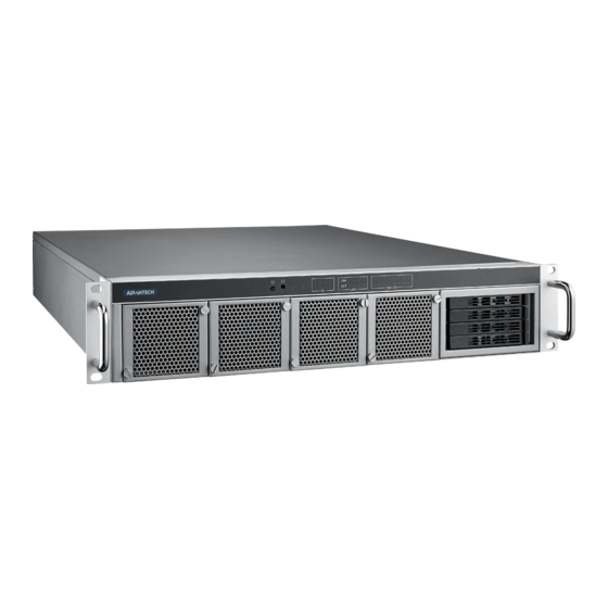
- Page 1 User Manual ECU-579 Series IEC-61850 Power Substation 2U Rackmount Server with ® ® Intel Xeon Scalable Processor...
- Page 2 No part of this manual may be reproduced, copied, translated, or transmitted in any form or by any means without the prior written permission of Advantech Co., Ltd. The information provided in this manual is intended to be accurate and reliable.
- Page 3 Product Warranty (2 years) Advantech warrants the original purchaser that each of its products will be free from defects in materials and workmanship for two years from the date of purchase. This warranty does not apply to any products that have been repaired or altered by persons other than repair personnel authorized by Advantech, or products that have been subject to misuse, abuse, accident, or improper installation.
- Page 4 This product has passed the CE test for environmental specifications when shielded cables are used for external wiring. We recommend the use of shielded cables. This type of cable is available from Advantech. Please contact your local supplier for ordering information.
- Page 5 IEC 704-1:1982 should be no more than 70 dB (A). DISCLAIMER: This set of instructions is given according to IEC 704-1. Advantech disclaims all responsibility for the accuracy of any statements contained herein.
- Page 6 ECU-579 User Manual...
-
Page 7: Table Of Contents
System Hardware ................. 3 1.2.3 I/O Interface .................. 3 1.2.4 Environment.................. 3 Function Block Diagram ................4 Figure 1.1 ECU-579 Series Product Function Block....4 Safety Precautions ..................4 Chassis Dimensions.................. 5 Figure 1.2 ECU-579 Chassis Dimensions ........5 Packing List....................5 Chapter Hardware Specifications .....7... - Page 8 Table 2.9: Tested Intel® Xeon® Scalable Series CPU List..21 2.10 Memory ....................22 2.10.1 Configurations with a Single CPU..........22 Table 2.10:DIMM Configurations..........22 2.10.2 Validated Memory............... 23 Table 2.11:DIMM Configurations with a Single CPU....23 2.11 TPM ......................24 2.12 Platform Feature Description ..............
-
Page 9: Chapter 1 Overview
Chapter Overview This chapter provides an overview of the ECU-579 Series specifica- tions. Sections include: Introduction Hardware Specifications Safety Precautions Function Block Diagram Chassis Dimensions Packing List... -
Page 10: Introduction
To fulfill the per- formance requirements of modern distributed software applications which require fast processing, Advantech offers ECU-579 which is targeted at advanced server-level data concentrators and protocol converters in scenarios like substation automation, energy management, secondary communication and control, etc. -
Page 11: Hardware Specifications
Hardware Specifications 1.2.1 General Certifications: CE, FCC Class A, IEC61850-3, IEEE 1613 Dimensions (W x D x H): 440 x 460 x 88 mm Enclosure: SECC & Aluminum Mounting: 2U 19” Rackmount Power Requirements: – Power 1: 100 ~ 240 V (50 ~ 60 Hz) –... -
Page 12: Function Block Diagram
Caution! Always ground yourself to remove any static electric charge before touching the ECU-579 series. Modern electronic devices are very sensi- tive to static electric charges. Use a grounding wrist strap at all times. -
Page 13: Chassis Dimensions
Chassis Dimensions Figure 1.2 ECU-579 Chassis Dimensions Packing List The package of the ECU-579 Series contains the following items: The main ECU-579 unit Accessory box (screws, jumpers, 1 x Startup Manual) 1 x warranty card 1 x ROHS LIST ... - Page 14 ECU-579 User Manual...
-
Page 15: Chapter 2 Hardware Specifications
Chapter Hardware Specifications Sections include: Overview Front Elements (LED, FAN, SATA Slots) Power Input Ethernet Interface (On-Board) Display Interface USB Expansion Functions Storage (SATA, M.2) Processors Memory TPM Platform Features Description ... -
Page 16: Overview
Overview 2.1.1 ECU-579 LED and Interface Figure 2.1 ECU-579 Front Panel Figure 2.2 ECU-579 Rear Panel Front Elements 2.2.1 LED Indicators The LEDs on the front panel can be divided into 4 groups. 2.2.1.1 System Status Indicators SATA Table 2.1: Definition of System Status Indicators Status Description Green... - Page 17 2.2.1.3 Programmable LED The ECU-579 Series products provide 8 programmable LED indicators which are convenient for users to control the programmable LED state (green, off) using API programming. They can be used to indicate and edit the machine’s operating status.
- Page 18 2.2.1.4 Slot LED The Slot LED is different according to the corresponding expansion card. Here, we take the LED definition of UNOP-1514RE/PE as an example to show how it is defined. Other LEDs are defined according to the description of the relevant expan- sion card and manual.
-
Page 19: Fan Modules
2.2.2 Fan Modules The ECU-579 has four hot-swappable fan modules at the front. Each of the fan mod- ules carries a high performance fan for optimized air flow. Each fan module is secured by two thumbscrews. We have a unique patent design to ensure no loss of fan air volume, even if one of the fan modules is broken. -
Page 20: Disk Bay
2.2.3 Disk Bay ECU-579 supports four hot-swappable 2.5” HDDs/SSDs at the front. Follow these steps below to install an HDD: Remove the baffle on the right of the front panel, and pull out the disk tray. Figure 2.4 Removing the SATA Baffle ECU-579 User Manual... - Page 21 Fix the SATA disk onto the tray and push it back into the disk bay. Then attach the baffle in front of the SATA bay. Figure 2.5 Fixing the SATA Disk onto the Disk Tray ECU-579 User Manual...
-
Page 22: Power Input
Power Input The ECU-579 Series products support redundant power input for both A/C and D/C. Table 2.5: Power Input Item AC/DC Voltage Range Power Rating Installation 100-240 V 10-5 A 50-60 Hz Plug-in D/C (Only for ECU- 100-240 V 10-5 A 579-SSDB) Figure 2.6 Power Installation Position... -
Page 23: Ethernet Interface
Ethernet Interface The ECU-579 Series products are equipped with Intel® 4 x Giga LAN. LAN1 port is shared with the IPMI function. 2.4.1 MAC Address You can identify MAC addresses according to the labels placed on Ethernet connec- tors as shown below. -
Page 24: Display Interface
Display Interface ECU-579 is configured with dual DVI connectors and one VGA connector. You can set up the display through BIOS. Note! “Onboard device” is the option for VGA output. “PCIe device” is the option for DVI output. Figure 2.7 Display Position The first time getting started with a bare sever, the operating system needs to be installed. -
Page 25: Expansion Slots
Through the interface card, the ECU-579 Series can also use standard PCI cards, PCIe cards, mini-PCI cards, as well as PCI-104 cards. Due to the ECU-579 Series being an embedded system, the power provided for the expansion slot is limited. -
Page 26: Pcie Expansion Cards
2.7.1.2 Proprietary PCI/PCIe Card List Below is the list of proprietary cards compatible with ECU-579: Table 2.8: Proprietary PCI/PCIe Card List ECU Standard P/N Description ECU-P1618D-AE 8-port RS-232/422/485 serial port card ECU-P1628D-AE 8-port isolated RS-232/422/485 serial port card ECU-P1524PE-GAE 2-port SFP Gigabit Ethernet Card with HSR/PRP ECU-P1761A-AE 4-ch Digital input 4-ch relay output card with IRIG-B UNOP-1624D-AE... - Page 27 Part Number Description Quad Port Copper Gigabit Ethernet PCI Express Server Adapter PCIE-1130PS-00A1E ® with Intel I350 (Advantech Form Factor) Quad Port Fiber Gigabit Ethernet PCI Express Server Adapter with PCIE-2130NP-00A1E ® Intel I350 Quad Port Fiber 10GbE Ethernet PCI Express Server Adapter with PCIE-2230NP-00A1E ®...
-
Page 28: Storage (Sata, M.2)
Storage (SATA, M.2) 2.8.1 SATA Disks ECU-579 provides 4 slots for 2.5” SATA disks which support RAID 0, 1, 5, 10. 2.8.2 M.2 Storage The M.2 2280 connector supports both SATA and PCIe SSD devices for higher read/ write speeds. M2_2280_1 Figure 2.11 M.2 Connector Position on the Main Board ECU-579 User Manual... -
Page 29: Processors
Processors 2.9.1 Compatible with Intel® Xeon® Scalable Series CPU ECU-579 is equipped with one CPU socket to support Intel® Xeon® Platinum/Gold/ Silver/Bronze Scalable series processors with up to 28 cores. Table 2.9: Tested Intel® Xeon® Scalable Series CPU List Test Item Description Result Remark Number... -
Page 30: Memory
2.10 Memory ECU-579 has 12 x 288-pin memory slots for DDR4 2133/2400/2666 MHz memory modules with a maximum total capacity of 768 GB (maximum 64 GB for each DIMM). ECU-579 supports registered DIMM memory modules. 2.10.1 Configurations with a Single CPU A total of 12 DDR4 DIMMs are supported on the ECU-579 equally spread over one processor socket with a total capacity of up to 768 GB. -
Page 31: Validated Memory
DIMMF1 DIMMC2 DIMMC1 2.10.2 Validated Memory Advantech has tested a list of RAM for your reference, and these are verified as com- patible with ECU-579 under our test. Table 2.11: DIMM Configurations with a Single CPU Test Item Description Result Remark... -
Page 32: Tpm
Table 2.11: DIMM Configurations with a Single CPU XECU- Advantech 4 GB 2666 DDR4 Y 2400 D4U4GR26- PASS SGTR 2.11 ECU-579 supports Trusted Platform Module (TPM 2.0) technology. TPM is designed to provide hardware-based security-related functions. TPM is a microchip designed to provide basic security-related functions primarily involving encryption keys. -
Page 33: Watchdog
To get the driver and test case for Windows and Linux operating systems, you can visit the official Advantech website on the ECU-579 product page to download the driver with the test sample. - Page 34 Figure 2.13 BMC Position To enable the IPMI function, you need to set it up in BIOS. First, enter the IP of the ECU-579 LAN1 you are using or use DHCP mode to get the IP address automati- cally. Then enter the IP address to initialize the IPMI network interface to start remote control.
-
Page 35: Available Accessories
Figure 2.14 IPMI Interface Note! If you need to remotely operate the BIOS, only VGA display mode sup- ports this function. 2.13 Available Accessories 2.13.1 Spare Parts The following spare parts are available for ordering: Table 2.12: Spare Parts Order Part Number Description XECU-FSP800-20FN Power module... - Page 36 ECU-579 User Manual...
-
Page 37: Chapter 3 Initial Setup And Configuration
Chapter Initial Setup and Configuration Sections include: Jumper Indication BIOS Setup and System Assign- ments Installing Components (CPU, RAM, SATA, PCIe Cards) Replacing Components... -
Page 38: Jumper Positions
Jumper Positions ECU-579 has 7 jumpers in case you need to implement certain functions. Table 3.1: Jumper List Jumper Position Name Function PSON1 AX mode: 1-2 short / ATX mode: 2-3 short (default) JTHR_SEL1 Thermal sensor on board (default): 1-2 short / external: 2-3 short JWDT1 Watchdog enable: 1-2 short (default) / disable: 2-3 short JCMOS1... -
Page 39: Bios Setup And System Assignments
BIOS Setup and System Assignments 3.2.1 System Date / System Time Use this option to change the system time and date. Highlight System Time or Sys- tem Date using the <Arrow> keys. Enter new values through the keyboard. Press the <Tab>... -
Page 40: Trusted Computing
3.2.3 Trusted Computing Security Device Support Enables or disables BIOS support for security devices. ECU-579 is equipped with Advantech’s LPC TPM 2.0 module to enable the trusted computing function. ECU-579 User Manual... -
Page 41: Platform Configuration
3.2.4 Platform Configuration 3.2.5 Socket Configuration ECU-579 User Manual... -
Page 42: Server Management
3.2.6 Server Management 3.2.7 Security ECU-579 User Manual... -
Page 43: Boot Options
3.2.8 Boot Options ECU-579 User Manual... -
Page 44: Installing Components
Installing Components When starting with ECU-579, basic components like the CPU and RAM are neces- sary to be installed first. In this chapter, we will show pictures with indications to guide you through the steps of installing components. Firstly, you need to open the chassis by unscrewing at the points shown in the picture below. -
Page 45: Installing The Cpu
3.3.1 Installing the CPU To install the CPU, you need to take off the wind scooper and unscrew the cooling fin. Figure 3.3 Taking Off the Wind Scooper ECU-579 User Manual... - Page 46 Figure 3.4 Taking Off the Cooling Fin Pay attention to ensure the orientation of the CPU is consistent with that of the CPU bracket and the cooling fin. Install the CPU into the CPU bracket and then re-attach the cooling fin. Then install the CPU bracket back to the main board. ECU-579 User Manual...
- Page 47 Figure 3.5 Fixing the CPU into the Bracket ECU-579 User Manual...
-
Page 48: Installing Ram
3.3.2 Installing RAM Memory performance is affected by different DIMM configurations. For optimal mem- ory interleaving, be sure to install identical DIMM types with the same size, speed, and number of ranks on the memory slots corresponding to the correct processor. RAM Installation Position Note! If only one RAM card is installed into a slot, it should be installed in the... - Page 49 Figure 3.6 Full Quantity of Memory Installed ECU-579 User Manual...
-
Page 50: Installing Storage Disks Using Sata And M.2
3.3.3 Installing Storage Disks Using SATA and M.2 First remove the baffle as shown in the picture below. Pull out the disk tray. Figure 3.7 Removing the HDD Baffle Use the screws in the accessory box to fix the hard disk onto the tray, and push it into the disk drawer. - Page 51 Figure 3.8 Attaching the Hard Disk You may add one M.2 hard disk in the position shown below. ECU-579 User Manual...
-
Page 52: Installing A Proprietary Pci/Pcie Card
Figure 3.9 Installing an M.2 Disk into Position 3.3.4 Installing a Proprietary PCI/PCIe Card You can install one proprietary PCI/PCIe card without opening the chassis on the back panel in the position shown below after removing the baffle. You can find the proprietary card list in Section 2.7.1. -
Page 53: Installing A Low-Profile Pcie Card
3.3.5 Installing a Low-Profile PCIe Card You can install 4 low-profile PCIe cards in most in the positions shown below. Figure 3.11 Low-Profile PCIe Card Installation Position ECU-579 User Manual... - Page 54 No part of this publication may be reproduced in any form or by any means, such as electronically, by photocopying, recording, or otherwise, without prior written permission from the publisher. All brand and product names are trademarks or registered trademarks of their respective companies. © Advantech Co., Ltd. 2022...
Need help?
Do you have a question about the ECU-579 Series and is the answer not in the manual?
Questions and answers