Table of Contents
Advertisement
Quick Links
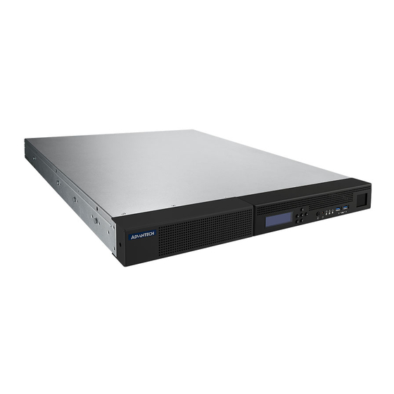
VEGA-7030
Author
Lori Yu
Status
Version 1.00
Document ID
History
Version
Date
V0.01
2024/1/10
V0.02
2024/4/9
V0.03
2024/5/21
V1.00
2024/6/11
Approved by
Date
Approved By
2024/6/17
Ian Tung
Platform User Guide
Handled by
Lori Yu
Thomas Lien
Lori Yu
Lori Yu
Page
Comments
Draft
Draft
Draft
Formal Release
1
of
62
Advertisement
Table of Contents

Related Manuals for Advantech VEGA-7030


Summary of Contents for Advantech VEGA-7030
- Page 1 VEGA-7030 Platform User Guide Author Lori Yu Status Version 1.00 Document ID History Version Date Handled by Comments V0.01 2024/1/10 Lori Yu Draft V0.02 2024/4/9 Thomas Lien Draft V0.03 2024/5/21 Lori Yu Draft V1.00 2024/6/11 Lori Yu Formal Release Approved by...
-
Page 2: Table Of Contents
Tools ............................12 2.1.3 Precautions ..........................13 Installing Motherboard Component ..................14 2.2.1 Removing the chassis cover Follow the instructions to remove VEGA-7030 chassis..14 2.2.2 Installing Memory Modules ..................... 15 2.2.3 Replace solid state drive ......................16 2.2.4 Install M.2 NVME SSD ...................... - Page 3 Server Management (Mgmt) Setup ..................50 3.9.1.1 BMC Network Configuration ....................51 3.9.1.2 BMC Self Test Log ........................52 3.9.1.3 System Event Log ........................52 BMC Setup ............................53 Overview ........................... 53 Confidence Monitor SDK Usage (OLED SDK) ................55 Files ............................
-
Page 4: Introduction
1. Introduction Overview Advantech high density 1U Rack-mount video server is designed for the multi-channel 4K acquisition with HEVC encode and also Video-over-IP solution. VEGA-7030 is a highly scalable and flexible video server platform for enabling multi-channel Ultra-HD, Full-HD and mobile video acquisition, processing, recording and streaming, VEGA-7030 delivers unprecedented superiority of broadcasting quality and channel-density within a standard IT 1U rack-mount system with low power budget. - Page 5 Onboard Ethernet Ports Traffic ports 4 LAN port on board Ethernet controller Intel I226 x3, I210 x1 System Storage HDD type (SAS, SATA….etc) SATA-III, RAID 0,1 (Intel software RAID) HDD form factor (3.5", 2.5" 2.5"…etc) NVME/m.2 slot Two m.2 NVME only: 2x 2280 LCM module Text/Graphic mode Text mode...
-
Page 6: System Layout, Led, Jumpers, Power And Connectors
System Layout, LED, Jumpers, Power and Connectors Connectors on the VEGA-7030 are linked to external devices such as SSD. In addition, VEGA-7030 has a jumper that is used to clean CMOS for BIOS. The tables below list the functions of each jumper and connector. Later sections in this chapter give instructions for setting jumpers. -
Page 7: Led Status
1.3.1 LED status State Color Description Green System in tuned on Power LED (Left) No power HW Fault LED by user programming (Middle) by user programming Alert by user programming Green by user programming (Right) by user programming Rear I/O LED Blinking Green LAN active... -
Page 8: Connectors
SATAIII x 2 connector PCIE Riser card 1 Riser Card #1 (2* PCIe x8 connector) PCIE Riser card 2 Riser Card #2 (2* PCIe x8 connector) 1.3.4 Power Input Rating for VEGA-7030 is 100-240V~, 8-4A , 50-60Hz. (Rating for each AC PSU) Page... -
Page 9: Block Diagram
Block diagram Figure 1 VEGA-7030 Block Diagram System Memory VEGA-7030 has two 288-pin memory slots for DDR5 memory modules with maximum capacity of 64GB (Maximum 32GB for each DIMM slot). VEGA-7030 supports W/ ECC or W/O ECC UDIMM only. Page... -
Page 10: Memory Installation Procedures
Memory installation procedures DIMM A0 DIMM B0 Page... -
Page 11: Hardware Setting Up
2. Hardware Setting up Before you Begin This chapter explains how to install DIMM, PCIE add-on cards, and SSD. Before removing the BMC, you must first enter the BIOS to modify the settings in order to boot without the BMC. 1. -
Page 12: Work Area
4. Turn off AC power & remove BMC module 2.1.1 Work Area Make sure you have a stable, clean working environment. Dust and dirt can get into components and cause malfunctions. Use containers to keep small components separated. Putting all small components in separate containers prevents them from becoming lost. Adequate lighting and proper tools can prevent you from accidentally damaging the internal components. -
Page 13: Precautions
Components and electronic circuit boards can be damaged by discharges of static electricity. Working on a system that is connected to a power supply can be extremely dangerous. Follow the guidelines below to avoid damage to VEGA-7030 or injury to yourself. ... -
Page 14: Installing Motherboard Component
This section describes how to install components on to the mainboard, including memory modules and add-on cards. Removing the chassis cover 2.2.1 Follow the instructions to remove VEGA-7030 chassis. 1. Unscrew the top cover from both sides and rear side of chassis. Figure 2.1... -
Page 15: Installing Memory Modules
2. Slide the rear top cover out. Figure 2.2 2.2.2 Installing Memory Modules Align the memory module with the slot. When inserted properly, the memory slot locking levers lock automatically onto the indentations at the ends of the module. Page... -
Page 16: Replace Solid State Drive
Figure 2.3 2.2.3 Replace solid state drive VEGA-7030 supports two 2.5” solid state drives. Follow these instructions to replace a drive. 1. Remove SATA power/data cables, and unscrew the SSD cage Figure 2.4 2. Unscrew SSD from the SSD cage... -
Page 17: Install M.2 Nvme Ssd
Figure 2.5 2.2.4 Install M.2 NVME SSD M.2 NVME SSD can be installed/removed by the screws. Figure 2.6 Page... -
Page 18: Install Riser Cards And Generic Pcie Cards
2.2.5 Install riser cards and generic PCIe cards 1. Loose thumbscrew. Figure 2.7 2. Loose screws on the back panel. Make sure the thumb screws are fully disengaged. Change Pic with empty slot. Figure 2.8 3. Take riser card cage out from the chassis Page... - Page 19 Figure 2.9 4. Install PCIe add-on card. Insert the PCIe card into the PCIe riser. Figure 2.10 5. Screw the I/O bracket Page...
- Page 20 Figure2.11 3. Install the riser card to the card cage. Figure 2.12 4. After inserting the riser card, then tighten thumbscrew. Page...
- Page 21 Figure 2.13 Page...
- Page 22 Install sliding rails (optional) Page...
-
Page 23: Ami Aptio Bios Setup
This section describes the AMI APTIO BIOS, UEFI compliant, which has been specifically adapted to the VEGA-7030. With the AMI APTIO BIOS Setup program, users can modify BIOS settings and control the special features of the VEGA-7030. The setup program uses a number of menus for making changes and turning special features on or off. - Page 24 Page...
-
Page 25: Main Setup
Main Setup When users first enter the BIOS Setup Utility, users will enter the Main setup screen. Users can always return to the Main setup screen by selecting the Main tab. Two main setup options are described in this section. The main BIOS setup screen is shown as below. The main BIOS setup menu screen has two main frames. -
Page 26: System Language
Megatrends Core Version X.YYY Display the BIOS Core version Compliancy UEFI X.Y Display the UEFI Platform Initialization PI W.Z version. Project VEGA-7030 Display BIOS version Version 7030000V0XX Build Date mm/dd/yyyy Display BIOS build date & time. and Time hh:mm:ss System English Display BIOS support language. -
Page 27: Platform Setup
Platform Setup Select the Platform tab from the VEGA-7030 setup screen to enter the Platform setup screen. Users can select any of the items in the left frame of the screen, such as Serial Console, to go to the sub menu for that item. Users can display the Platform setup option by highlighting it using the <Arrow>... -
Page 28: Serial Console
3.4.1 Serial Console Figure 3.4 Serial Console Settings Table 3.2 Serial Console Settings Feature Option Description Help text Console Enabled Enable or disable console Console redirection. redirection. Redirection Disabled Serial COM1 Configure serial port for console Select Console port. Console Port redirection. - Page 29 Space bit of the serial data for both 1's in the data bits is even. serial ports. Odd: parity bit is 0 if the number of 1's in the data bits is odd. Mark: parity bit is always 1. Space: Parity bit is always 0.
-
Page 30: Usb Configuration
Redirection The Settings specify if The Settings specify if Always Enable After BIOS BootLoader BootLoader is selected, then BootLoader is selected, then POST Legacy console redirection is Legacy console redirection is disabled before booting to disabled before booting to Legacy OS. Default value is Legacy OS. -
Page 31: Trusted Computing
3.4.3 Trusted Computing Figure 3.6 Trusted Computing Table 3.4 Trusted Computing Feature Option Description Help text Disable Security Enable or disable BIOS support for Enable or disable BIOS support for Enable Device security device. O.S. will not show security device. O.S. will not show Support Security Device. -
Page 32: Virtualization
Pending Select this None to prevent the Schedule an Operation for the None operation TPM Clear system from running any TPM Security Device. commands. Select TPM Clear to allow the system to run an TPM Clear command during the next boot. Platform Disabled Enable or disable Platform... - Page 33 Feature Option Description Help text Intel Enabled Enable or disable BIOS support Enable the Vanderpool Technology, Virtualiza Disabled for the Vanderpool Technology take effect after reboot. tion Technolo Intel(R) Enabled Enable or disable Intel Enable or disable Intel Virtualization VT-d Disabled Virtualization Technology for Technology for Directed I/O (VT-d)
-
Page 34: Platform Management
3.4.5 Platform Management Figure 3.8 Platform Management Table 3.6 Platform Management Feature Option Description Help text Intel speed Disabled Enable or disable processor Turbo Turbo mode allows a CPU logical step Enabled mode.Turbo mode allows a CPU processor to execute a higher logical processor to execute a frequency when enough power is higher frequency when enough... -
Page 35: Nct6126D Hw Monitor
3.4.6 NCT6126D HW Monitor System health information Figure 3.9 System health information Page... -
Page 36: Hardware Setup
Hardware Setup Select the chipset tab from the VEGA-7030 setup screen to enter the Hardware setup screen. Users can configure the parameters of CPU configuration, Northbridge and Southbridge, respectively. Figure 3.10 Hardware Settings Page... -
Page 37: Cpu Configuration
3.5.1 CPU configuration Figure 3.11 CPU Configuration Table 3.9 CPU Configuration Feature Option Description Help text Hardware Enabled Enable or disable Hardware To turn on/off the MLC streamer Prefetcher Disabled Prefetcher feature. prefetcher Adjacent Cache Enable or disable Adjacent To turn on/off prefetching of Enabled Line Prefetch Disabled... -
Page 38: Northbridge
3.5.2 Northbridge Users can set up all parameters related to the IOH function in the North Bridge page. Moreover, the VEGA-7030 BIOS allows users to configure the PCIe setting. Figure 3.12 Northbridge Configuration Table 3.10 Northbridge Configuration Feature Option Description... -
Page 39: Dimm Information
3.5.2.1 DIMM Information Figure 3.13 DIMM Information Page Page... -
Page 40: Graphic Configuration Information
3.5.2.2 Graphic Configuration Information Figure 3.14 Graphics Configuration Page Feature Option Description Help text Primary Display Auto Select Primary Display Select which of IGFX device IGFX/PEG/PCI Graphics PEG Slot device should be Primary Display Internal Graphics Auto Enable or Disable Internal Keep IGFX enabled based on Graphics controller Disabled... -
Page 41: Southbridge
Users can set up all parameters related to the PCH function in the South Bridge page. Also, users can configure (to enable or disable) three USB ports (2.0 and 3.0) supported on the VEGA-7030 in this page. Figure 3.15 Southbridge Configuration Table 3.13 Southbridge Configuration... - Page 42 2. BMC ESPI interface Disable > Enable 3. Save & Exit > Save Change and Reset Turn off AC power & remove BMC module Page...
-
Page 43: Sata Configuration
3.5.3.1 SATA Configuration Figure 3.16 SATA Configuration Page... - Page 44 Table 3.14 SATA Configuration Feature Option Description Help text SATA Disabled Enable or Disable SATA Controllers Enable/Disable SATA Controller Enabled SATA AHCI Determines how SATA Mode controller(s) operate. Selection Port 4 Disabled Enable or Disable SATA4 port Enable or Disable SATA4 port Enabled Hot Plug Disabled...
-
Page 45: Acpi Settings
3.5.3.2 ACPI Settings Figure 3.17 ACPI Settings Table 3.16 ACPI Settings Feature Option Description Help text Enable ACPI Enabled Enable or disable BIOS ACPI Enable or disable BIOS ACPI Auto Auto Disabled Auto Configuration. Configuration. Configuratio Page... -
Page 46: Boot Setup
Boot Setup The Post & Boot menu allows configuring POST behavior and boot options. Figure 3.18 Boot Configuration Table 3.19 Boot Configuration Feature Option Description Help text Setup 0 to 65535 Number of seconds to wait for Number of seconds to wait for setup Prompt setup activation key. - Page 47 Figure 3.19 Hard Disk Driver BBS Priorities Page Page...
-
Page 48: Security Setup
Security Setup The Security page allows enabling password protection and entering passwords. When logging at Administrator level, all configuration parameters can be modified. If Administrator password is enabled and Password Check is Setup, the BIOS will prompt the user for a password before entering the setup menu. If Administrator password is enabled and Password Check is Always, the BIOS will prompt the user for a password before entering the setup menu and entering OS. -
Page 49: Save & Exit Option
Save & Exit Option The Save & Exit page provides different options to exit the setup menu and to restore default values for all configuration parameters. Figure 3.21 Save & Exit Configuration Table 3.23 Save & Exit Configuration Feature Option Description Help text Save... -
Page 50: Server Management (Mgmt) Setup
Save Save modified settings into non- Reset the system after saving the Changes volatile memory and reboots the changes. and Reset system. Discard Discard modified settings, reverts to Reset system setup without saving Changes the state when setup was entered and any changes. -
Page 51: Bmc Network Configuration
Table 3.18 Server Mgmt Configuration Feature Option Description Help text BMC Self Test Show BMC Self-Test Status Status OS Watchdog Enabled Enable or disable OS If enabled, start a BIOS timer Timer watchdog Timer which can only be shut off by Disabled Intel Management Software after the OS loads. -
Page 52: Bmc Self Test Log
Figure 3.23 BMC Network Configuration Feature Option Description Help text Configuration Unspecified Configure BMC IP address Select to configure LAN Address source Static to static IP or DHCP channel parameters statically or DynamicBMCDhcp dynamically(by BIOS). Unspecified will not modify any BMC network parameter during BIOS. -
Page 53: Bmc Setup
4. BMC Setup Overview The IPMI functionality of VEGA-7030 is provided by Advantech BMC which is implemented on ASPEED AST2600. The implementation is intended to comply with IPMI 2.0. The IPMI function list of VEGA-7030 includes the following. - Page 54 Node Explorer UM: https://www.advantech.com/en/support/details/manual?id=1- 1MU1KB1&_gl=1*bj9y70*_ga*MTg3MzU5MDI5MS4xNjkyMTUzNjcx*_ga_LS3NMY5FLH* MTcxNTY1MDcwNi4yNS4wLjE3MTU2NTA3MDkuNTcuMC4w Page...
-
Page 55: Confidence Monitor Sdk Usage (Oled Sdk)
5. Confifence Monitor SDK (OLED SDK) Usage Files README fttest - test FT2xxx devices lsspi - list spi devices 262k - oled test program for RGB 666 color space - oled test program for RGB 565 color space ... -
Page 56: Usage
3. If running this demo project for the first time, please select 2896 panel $ sudo ./262k Please press 0 to select 2896 panel which is used in VEGA-7030. 4. If want to select new panel: remove .spioled file to select new panel or $ sudo ./262k -sel... - Page 57 ClearScreen F Pattren Red Color Green Color Blue Color Black Color White Color Other Patterns... Page...
- Page 58 $ sudo ./262k -h 7. The usage of 64k program is same as 262k 8. $ sudo ./movplayer ../Advantech.mp4 If you fail to run movplayer, it is probable cause of different ffmpeg version. Because the version of ffmpeg package install may be not same as movplayer used, to get rid of the issue you must rebuild movplayer with your system's ffmpeg library.
-
Page 59: Lcm Sdk Usage
6. LCM SDK Usage Files README bin/70xxlcm_test - LCM test program for vega70xx bin/70xxlcm_demo - LCM demo program for vega70xx bin/70xxlcm-setlogo - Set the LCM startup screen for vega70xx *.c *.h - source of lcm programs Installation 1. - Page 60 3. 70xxlcm_demo A. You need root privilege to run the test program $ sudo ./70xxlcm_demo Or use -p to select the actual device for the uart port $ sudo ./70xxlcm_demo -p /dev/ttyS1 The 70xxlcm_demo program is a demo code that provides a simple demonstration of showing and setting the iP address The default eth name of management port is "enp6s0".
-
Page 61: Troubleshooting
Usage: $ sudo ./70xxlcm-setlogo <OPTION> [-p <UART PORT>] <OPTION> : Set the startup screen to 'ADVANTECH' -c "STRING" : Set the startup screen to 'STRING' : Set the module mode to 16x2 : Test the LCM <UART PORT> The port is the actual device for the serial port. -
Page 62: Caution
7. Caution 1. The power supply cord(s) must be plugged into socket-outlet(s) that is / are provided with a suitable earth ground. Cet équipement doit être branché à une prise correctement reliée à la terre. 2. This product is not intended for use by children (this product is not a toy). This equipment is not suitable for use in locations where children are likely to be Presented.
Need help?
Do you have a question about the VEGA-7030 and is the answer not in the manual?
Questions and answers