Table of Contents
Advertisement
Quick Links
Advertisement
Table of Contents

Related Manuals for Advantech B+B SmartWorx Vlinx VESR424D


Summary of Contents for Advantech B+B SmartWorx Vlinx VESR424D
- Page 1 Vlinx™ Serial Server Model VESR424D USER MANUAL...
- Page 2 VESR424D Serial Server Advantech B+B SmartWorx - Americas 707 Dayton Road Ottawa, IL 61350 USA Phone (815) 433-5100 Fax (815) 433-5105 Advantech B+B SmartWorx - European Headquarters Westlink Commercial Park Oranmore, Co. Galway, Ireland Phone +353 91-792444 Fax +353 91-792445 www.advantech-bb.com support@advantech-bb.com...
-
Page 3: Table Of Contents
VESR424D Serial Server CONTENTS Chapter 1. INTRODUCTION ....................6 About VESR424D Serial Server ..................6 VESR424D ........................6 VESR424D Features ......................7 Vlinx Manager Configuration Software ................7 Chapter 2. VESR424D HARDWARE ................... 8 Package Checklist ......................8 LED Indicators ........................8 Power LED ........................ - Page 4 VESR424D Serial Server Serial Server Information Table ................... 21 Configuration Pane ...................... 22 Logging In ........................22 Navigating the Configuration Pages ................23 Setting Up the Serial Server Name and Password ............24 Changing the Serial Server’s Name ................24 Changing the Password: ....................
- Page 5 VESR424D Serial Server Advantech B+B SmartWorx Technical Support ..............58 Statements, Precautions ....................59 FCC Radio Frequency Interference Statement ............59 Electrostatic Discharge Precautions ................60 Disclaimer & Brand ...................... 60...
-
Page 6: Chapter 1. Introduction
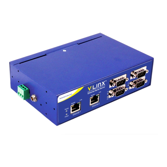
VESR424D Serial Server CHAPTER 1. INTRODUCTION Thank you for purchasing the VESR424D Serial Server product. This product has been manufactured to the highest standards of quality and performance to ensure your complete satisfaction. Figure 1. VESR424D Serial Server ABOUT VESR424D SERIAL SERVER Model VESR424D Serial Server connects serial devices (RS-232, RS-422 or RS-485) to Ethernet networks, allowing the serial device to become a node on the network. -
Page 7: Vesr424D Features
VESR424D Serial Server VESR424D FEATURES • Two Ethernet connectors • Ethernet pass through ports • Multi-interface serial ports (RS-232, RS-422, RS-485) • DB9 male serial port connector options • All serial ports are software selectable for RS-232, RS-422 or RS-485 2-wire and 4-wire communication •... -
Page 8: Chapter 2. Vesr424D Hardware
VESR424D Serial Server CHAPTER 2. VESR424D HARDWARE VESR424D Serial Server includes: • LED indicators • Power, Ethernet and Serial connectors • A recessed Reset (mode) switch PACKAGE CHECKLIST VESR424D Serial Server is shipped with the following items included: • VESR424x Serial Server Module •... -
Page 9: Ready Led
VESR424D Serial Server READY LED The Ready LED (green) illuminates continuously while the unit is initializing. It flashes once per second when the system is operating correctly. If the LED is not flashing, it indicates that something is wrong (e.g. another device on the network at the same IP address). ETHERNET SPEED LEDS (1 &... -
Page 10: Using The Reset Switch To Initiate A Hardware Reset
VESR424D Serial Server USING THE RESET SWITCH TO INITIATE A HARDWARE RESET Hold the Reset switch in for 0 to 2 seconds. The P1 LED illuminates while the switch is being held in. Release the switch in less than 2 seconds or else the serial server will enter Console Mode. -
Page 11: Serial Port Connectors
VESR424D Serial Server SERIAL PORT CONNECTORS Model VESR424D Serial Server features four serial ports and uses DB9M connectors for RS- 232, RS-422 and RS-485 connections. DB9M Serial Port Connector with Pinout (# VESR424D) NOTE: Refer to Appendix D for connector pinouts. POWER CONNECTOR The VESR424D serial server provides two power connectors. - Page 12 VESR424D Serial Server Each bracket is mounted using two 4-40 flat-head screws (included). The additional threaded holes on the side of the serial server allow the unit to be mounted in six different configurations. Figure 7. VESR424D Showing Panel Mount Bracket Options If extra mounting brackets are needed, they can be ordered from B+B SmartWorx (Kit PN# 9030).
-
Page 13: Chapter 3. Installation & Initial Setup
VESR424D Serial Server CHAPTER 3. INSTALLATION & INITIAL SETUP This section describes how to install the VESR424D Serial Server and configure the device. NOTE: In this section, devices to be connected to the serial server’s serial connections are referred to as the “serial device”. -
Page 14: Connecting Vesr424D Serial Server To A Network
VESR424D Serial Server RS-422 RS-422 connections support two signal pairs: TDA (-), TDB (+), RDA (-), RDB (+) and GND. The data lines are differential pairs (A & B) in which the B line is positive relative to the A line in the idle (mark) state. -
Page 15: Ethernet Pass-Through Port
VESR424D Serial Server ETHERNET PASS-THROUGH PORT Model VESR424D serial server is equipped with an additional RJ45 network port, also known as a “pass-through” port. This port can be used to connect additional Ethernet devices, such as a local workstation or second serial server to the network. Figure 11. -
Page 16: Configuring Via The Network Using A Browser
VESR424D Serial Server Figure 12. Network Setup CONFIGURING VIA THE NETWORK USING A BROWSER The VESR424D Serial Server can also be configured over the network using a standard internet browser such as Internet Explorer or Firefox running on a networked PC. To do so you must know the IP address of the serial server. -
Page 17: Vesr424D Serial Server Operational Connections
VESR424D Serial Server VESR424D SERIAL SERVER OPERATIONAL CONNECTIONS The VESR424x Serial ServerD can operate in Direct IP, Virtual COM Port and Paired Modes. In Direct IP Mode, applications can use TCP/IP socket connections or UDP/IP datagrams to communicate with the COM ports on the serial server. In this type of application, the serial server is configured as a TCP or UDP server. -
Page 18: Installing And Starting Vlinx Manager
VESR424D Serial Server Figure 15. Paired Mode Setup INSTALLING AND STARTING VLINX MANAGER Vlinx Manager is a Windows-based application used to configure serial servers. Install it on your PC from the included CD. Installation should launch automatically when the CD is placed in the CD-ROM drive. -
Page 19: Discovering Serial Servers
VESR424D Serial Server DISCOVERING SERIAL SERVERS If you are configuring the serial server via the network, select Network; if you are configuring it via the serial port, select Serial Port. If you already know the IP address of the serial server, click The device is at this IP address;... -
Page 20: Chapter 4. Configuring The Serial Server
VESR424D Serial Server CHAPTER 4. CONFIGURING THE SERIAL SERVER OVERVIEW OF THE VLINX MANAGER The Vlinx Manager Configuration window includes three areas: • Icons • Serial Server Information Table • Configuration Pane Figure 17. Vlinx Manager Configuration Window MANUAL NOTE: The screen shots shown in this manual refer to the VESR901 (a similar B+B SmartWorx serial server model). -
Page 21: Icons
VESR424D Serial Server ICONS Figure 18. Configuration Window Icons Open - Open a serial server configuration file. Save - Save the current serial server configuration to a file. Search - Initiate a search for serial server/s. Upgrade – Upgrade/upload firmware in a serial server - Add a Virtual COM Port to the host PC... -
Page 22: Configuration Pane
VESR424D Serial Server CONFIGURATION PANE The configuration pane is essentially a web browser. Figure 20. Configuration Pane It includes the following: Masthead with name and IP address of currently selected serial server Contents sidebar (on the left side) containing hyperlinks to the following configuration pages: General Network... -
Page 23: Navigating The Configuration Pages
VESR424D Serial Server Figure 21. Login Page 3. Click Login. The General Configuration page appears. NAVIGATING THE CONFIGURATION PAGES There are two ways to move from page to page in the Vlinx Manager software: by clicking a specific link, or by clicking Next Back to move through the pages sequentially. -
Page 24: Setting Up The Serial Server Name And Password
VESR424D Serial Server SETTING UP THE SERIAL SERVER NAME AND PASSWORD On the General Configuration page you can do the following: Change the name of the serial server. Initiate a login password change. Figure 22. General Configuration Page CHANGING THE SERIAL SERVER’S NAME 1. -
Page 25: Setting Up Ip Addressing
VESR424D Serial Server SETTING UP IP ADDRESSING On the Network Configuration page you can configure the serial server to use dynamic (DHCP) or static IP addressing on the network. Figure 24. Network Configuration Page SETTING UP DYNAMIC IP ADDRESSING 1. Select the I want to use DHCP to setup the network check box. -
Page 26: Setting Up Serial Ports
VESR424D Serial Server SETTING UP SERIAL PORTS On the Serial Port Configuration page you can configure the communications parameters of the current serial port. Parameters include the port mode, baud rate, data bits, parity, stop bits and type of flow control. Figure 26. -
Page 27: Setting Up Port Network Parameters
VESR424D Serial Server SETTING UP PORT NETWORK PARAMETERS On the Port Network Parameters Configuration page you can configure the port to use UDP, TCP. VCOM or Paired protocols in several different modes. TCP CONFIGURATION TCP (Transmission Control Protocol) provides reliable connection-oriented network communication with error checking. -
Page 28: Udp Configuration
VESR424D Serial Server SETTING THE SERIAL SERVER TO OPERATE AS A TCP CLIENT 1. Select protocol. 2. Select to initiate connections (client) 3. Type the IP address into the I want to connect to IP address: 4. Type the TCP port number of the server into the on TCP port number: box. - Page 29 VESR424D Serial Server All nodes at a specific UDP port number. (This is a broadcast message.) Specific IP addresses and UDP port numbers. (This is a unicast message.) A range of IP addresses and UDP port numbers. (This is a unicast range.) You can also configure the serial server to receive from nodes on the network using a similar list of configuration options.
- Page 30 VESR424D Serial Server only specific IP addresses (send unicast) - sends to specific network IP addresses (specified later) only a range of IP addresses (send unicast range) - sends to all IP addresses within a specified range (specified later) 3. Configure the Send IP addresses and port numbers: If you selected:...
-
Page 31: Setting Up Virtual Com (Vcom) Operation
VESR424D Serial Server SETTING UP VIRTUAL COM (VCOM) OPERATION When the Network Protocol is set to VCOM (Virtual COM Port), the serial server communicates over the network with a PC, acting as a remote COM port for the computer. Figure 30. VCOM Configuration NOTE: Both the serial server and the computer must be configured for VCOM operation. - Page 32 VESR424D Serial Server Figure 31. Paired Mode Configuration SETTING THE SERIAL SERVER TO OPERATE IN PAIRED MODE AS A CLIENT 1. Select Paired protocol. 2. Select to initiate connections (client). 3. Type the IP address and TCP port numbers of the server in the appropriate text boxes. 4.
- Page 33 VESR424D Serial Server 3. Type the TCP port number to be used in the I want to wait for connections on TCP port number box. 4. Select the number of connections in the and limit the number of connections to drop down box.
-
Page 34: Setting Up Advanced Network Settings
VESR424D Serial Server SETTING UP ADVANCED NETWORK SETTINGS On the Advanced Network Settings window, you can configure if network connections are automatically closed due to inactivity and when serial data is forwarded to the network. Data that is received by the serial port is normally buffered for a short period of time and then forwarded over the Ethernet to the remote device. -
Page 35: Configuring When Data Packets Are Sent
VESR424D Serial Server Figure 36. Advanced Configuration - Forcing Connections Closed TO CLOSE A NETWORK CONNECTION IF NO DATA IS RECEIVED FROM THE NETWORK FOR A PERIOD OF TIME 1. Select the I want to close a connection when data is not received on that connection for a period of time checkbox. - Page 36 VESR424D Serial Server Figure 37. Advanced Configuration - Configuring When Data Packets Are Sent TO WAIT UNTIL A SPECIFIC AMOUNT OF DATA IS RECEIVED ON THE SERIAL PORT BEFORE SENDING IT ACROSS THE NETWORK 1. Select: I want to wait for a specific amount of data to be received by the serial port before sending it in the Character Count...
- Page 37 VESR424D Serial Server TO FORCE THE SERIAL SERVER TO SEND BUFFERED DATA IF ANOTHER CHARACTER IS NOT RECEIVED WITHIN A CERTAIN PERIOD OF TIME 1. Select: I want to send data immediately when no more characters are received for in the Intercharacter Timeout box.
-
Page 38: Saving/Restoring The Configuration Settings
VESR424D Serial Server SAVING/RESTORING THE CONFIGURATION SETTINGS When all configuration windows are complete the Save Configuration page appears. Figure 38. Save Configuration Page TO SAVE THE CONFIGURATION TO THE SERIAL SERVER, AND RE-BOOT IT SO THAT THE CONFIGURATION SETTINGS WILL TAKE AFFECT. 1. -
Page 39: Removing Virtual Com Ports
VESR424D Serial Server 1. On the Vlinx Manager window, click the icon. Add Virtual COM Port dialog box appears. 2. Select the serial server you want to map the virtual COM port to. 3. Select the serial port number on the serial server. 4. -
Page 40: Chapter 5. Upgrading The Serial Server Firmware
VESR424D Serial Server CHAPTER 5. UPGRADING THE SERIAL SERVER FIRMWARE Occasionally, updated firmware may become available for your serial server. The firmware can be upgraded using the Vlinx Manager software. The following procedure describes the firmware updating process: 1. Click the Upgrade button to open the Firmware Upgrade... -
Page 41: Downloading Firmware Files
VESR424D Serial Server DOWNLOADING FIRMW ARE FILES Firmware File list (second box) displays all firmware files in the firmware installation folder. Only firmware that is compatible with the selected serial server is available in this list. TO DOWNLOAD THE LATEST FIRMW ARE FILES FROM AN FTP SITE ON THE INTERNET 1. -
Page 42: Chapter 6. Diagnostics
VESR424D Serial Server CHAPTER 6. DIAGNOSTICS Clicking the Diagnostics icon opens the Diagnostics dialog box and enables you to check the operation of connected serial servers and VCOM ports on the local computer. Computer Information box displays information about the type of network connections, the IP addresses, Subnet Masks and Default Gateways in use. -
Page 43: Testing A Virtual Com Port
VESR424D Serial Server Figure 43. Testing a Serial Server Connection TESTING A VIRTUAL COM PORT 1. Click the Diagnostics icon. The Diagnostics dialog box appears. 2. Select the option: a virtual communications port. 3. In the drop down box select the specific COM port you want to check. Start 4. -
Page 44: Chapter 7. Listing / Descriptions Of Serial Server Settings
VESR424D Serial Server CHAPTER 7. LISTING / DESCRIPTIONS OF SERIAL SERVER SETTINGS The following serial server properties are ordered alphabetically to assist you in finding the information you need. Baud Rate is the communication speed of the link between the serial server and the device attached to its serial port. - Page 45 VESR424D Serial Server How Delimiters Work. When only Delimiter 2 (the end delimiter) is enabled, characters received by the serial port are accumulated in a buffer. When the end delimiter is received on the serial port, the buffered characters, including the end delimiter, are sent to the network.
- Page 46 VESR424D Serial Server network packets, but decrease the amount of time to receive characters. The range is 1 through 65535. Inter-character Timeout controls the maximum duration between received characters before sending the characters to the network. Larger values may decrease the number of network packets, but increase the amount of time to receive characters.
- Page 47 VESR424D Serial Server Figure 46. TCP/IP Properties c. Use the Vlinx Manager Software to search for, discover, and configure the unit. 2. Method Two: Change the serial server’s network setting to match your PC using Console Mode d. Connect a null modem serial cable (cross-over cable) from any port on the serial server to an available COM port on your PC.
- Page 48 VESR424D Serial Server Configure the serial server to: IP Address = 192.168.0.50 Network Mask = 255.255.255.0 Default Gateway = 192.168.0.100 Save the settings and remove power from the serial server. Apply power to the serial server. Open the Vlinx™ Manager Software and select “Network” as the method to connect to the serial server.
- Page 49 VESR424D Serial Server Manager. The password is used to access the configuration pages from the Vlinx Manager Login page and can be changed from the General page. Serial Interface Modes. Four serial interface modes of operation are: RS-232 - Point-to-point serial communications connection used by PC COM ports and many other systems.
-
Page 50: Chapter 8. Appendices
VESR424D Serial Server For a Class C network (IP addresses 192.0.0.0 through 233.255.255.255) the default subnet mask is 255.255.255.0 For a Class D network (IP addresses 224.0.0.0 through 239.255.255.255) and Class E Networks (IP addresses 240.0.0.0 through 255.255.255.255) the subnet mask is ignored. VESR424x serial servers come from the factory with a default subnet mask value of: 255.255.255.0 TCP (Transmission Control Protocol) Mode provides reliable connection-oriented network communication with error checking. - Page 51 VESR424D Serial Server Setting Default Value Server Name VESR424D Serial Number Printed on side of unit. Password Password field is blank from factory. DHCP Enable BASED ON DHCP SERVER IP Address If a DHCP assignment is not available, the device will default to 169.254.102.39 Net Mask 255.255.255.0...
-
Page 52: Appendix B: Product Specifications
VESR424D Serial Server APPENDIX B: PRODUCT SPECIFICATIONS GENERAL SPECIFICATIONS Device Serial Server Hardware & CD with Vlinx Manager Software for: Windows 2000, XP (32/64 bit), Included 2003 Server (32/64 bit), Vista (32/64 bit), 2008 Server (32/64 bit), Accessories 2012 Server-r2 (32/64 bit), 7 (32/64 bit), 8 (32/64 bit), 10 (32/64 bit) Model# 232NM9 - Null Modem Crossover Cable, for DTE to DTE Cable connection... -
Page 53: Controls, Indicators And Connector Specifications
VESR424D Serial Server CONTROLS, INDICATORS AND CONNECTOR SPECIFICATIONS Switches Reset Button Hold in for 0 to 2 seconds for hardware reset. Hold in for 2 to 10 seconds for Console Mode (do a hardware reset or recycle power to exit Console Mode). Hold in for more than 10 seconds to reset to factory defaults. -
Page 54: Network Specifications
VESR424D Serial Server NETWORK SPECIFICATIONS Memory Serial Memory 8 KB per port 4 KB Network Memory I/P Port Addresses 5300 Heartbeat & Configuration setting in TCP Mode (i.e. Paired Mode) 8888 VESR424x update Network 10/100 Mbps auto-detecting 10BaseT or 100BaseTX Communications Network Physical Ethernet... - Page 55 VESR424D Serial Server 7000/tcp Always open for serial server This port is used for configuration and firmware upgrade of the device using the serial server manager. This port is configuration over TCP. always open, no matter how you configure the device. If you want to configure the serial server from outside of a firewall using the serial server manager, then the firewall must be configured to allow incoming connections on...
-
Page 56: Appendix C: Dimensional Diagram
VESR424D Serial Server APPENDIX C: DIMENSIONAL DIAGRAM Figure 47. Dimensional Diagram of VESR424D Serial Server. Units = inches [millimeters]... -
Page 57: Appendix D: Connector Pinouts
VESR424D Serial Server APPENDIX D: CONNECTOR PINOUTS DB9M CONNNECTOR DB9M Pin RS-232 Direction (RS-232) RS-422/485 4-Wire RS-485 2-Wire Input RDA (-) Input RDB (+) Output TDB (+) Data B (+) Output TDA (-) Data A (-) Input Output Input NOTE 1: In the RS-422 mode, TX lines are outputs and RX lines are inputs. Connect the serial server TXB(+) line to the RXB(+) line of the serial device, and the serial server TXA(-) to the RXA(-) of the serial device. -
Page 58: Standard Ethernet Cable Rj-45 Pinout
RJ45 Pin White-Green Green White-Orange Not used Blue Not used White-Blue Orange Not used White-Brown Not used Brown ADVANTECH B+B SMARTWORX TECHNICAL SUPPORT USA/Canada: 1 (800) 346-3119 (Ottawa IL USA) Europe: +353 91 792444 (Ireland / Europe) Email: support@advantech-bb.com Web: www.advantech-bb.com... -
Page 59: Statements, Precautions
VESR424D Serial Server STATEMENTS, PRECAUTIONS FCC RADIO FREQUENCY INTERFERENCE STATEMENT This equipment has been tested and found to comply with the limits for a Class A computing device, pursuant to Part 15 of the FCC Rules. These limits are designed to provide reasonable protection against harmful interference when the equipment is operated in a commercial environment. -
Page 60: Electrostatic Discharge Precautions
DISCLAIMER & BRAND © 2018 B+B SmartWorx – powered by Advantech. All rights reserved. The information in this document is subject to change without notice. B+B SmartWorx assumes no responsibility for any errors that may appear in this document. Ilinx VESR424D is a trademark of B+B SmartWorx. Other brands or product names may be trademarks and are the property of their respective companies.
Need help?
Do you have a question about the B+B SmartWorx Vlinx VESR424D and is the answer not in the manual?
Questions and answers