Advantech ADAM-4571 User Manual
1/2-port rs-232 serial device servers
Hide thumbs
Also See for ADAM-4571:
- User manual (72 pages) ,
- User manual (66 pages) ,
- User manual (74 pages)

Related Manuals for Advantech ADAM-4571


Summary of Contents for Advantech ADAM-4571
- Page 1 ADAM-4571/4570 1/2-port RS-232/422/485 Serial Device Servers ADAM-4571L/4570L 1/2-port RS-232 Serial Device Servers User Manual...
- Page 2 No part of this man- ual may be reproduced, copied, translated or transmitted in any form or by any means without the prior written permission of Advantech Co., Ltd. Information provided in this manual is intended to be accurate and reli- able.
- Page 3 Product Warranty (2 years) Advantech warrants to you, the original purchaser, that each of its prod- ucts will be free from defects in materials and workmanship for two years from the date of purchase. This warranty does not apply to any products which have been repaired or...
-
Page 4: Declaration Of Conformity
This product has passed the CE test for environmental specifications when shielded cables are used for external wiring. We recommend the use of shielded cables. This kind of cable is available from Advantech. Please contact your local supplier for ordering information. - Page 5 Safety Instructions Read these safety instructions carefully. Keep this User's Manual for later reference. Disconnect this equipment from any AC outlet before cleaning. Use a damp cloth. Do not use liquid or spray detergents for clean- ing. For plug-in equipment, the power outlet socket must be located near the equipment and must be easily accessible.
- Page 6 The sound pressure level at the operator's position according to IEC 704- 1:1982 is no more than 70 dB (A). DISCLAIMER: This set of instructions is given according to IEC 704-1. Advantech disclaims all responsibility for the accuracy of any statements contained herein. Safety Precaution - Static Electricity Follow these simple precautions to protect yourself from harm and the products from damage.
-
Page 7: Table Of Contents
Package Checklist ............. 5 1.4.1 ADAM-4571/4571L ............5 1.4.2 ADAM-4570/4570L ............5 Chapter 2 Getting Started ..........8 Understanding the Advantech ADAM-4570 Series..8 2.1.1 Network Architecture ............ 8 2.1.2 LED Indicators ............... 9 Table 2.1:ADAM-4570 Series LED Definition ..... 9 2.1.3 Dimensions (Unit: mm) .......... - Page 8 3.4.6 Advanced Settings ............42 Security Configuration ............ 43 3.5.1 Accessible Function ............. 43 3.5.2 Port Monitor ..............44 Fulfilling Administrator Functions........45 3.6.1 Import/Export Serial Port Setting ........ 45 3.6.2 Locate Serial Device ............ 46 3.6.3 Lock Device ..............46 3.6.4 Restore to Factory Default Settings ......
- Page 9 Overview...
-
Page 10: Chapter 1 Overview
Chapter 1 Overview 1.1 Introduction Advantech's ADAM-4570 series of Industrial Serial Device Servers are a robust, feature-rich, and cost effective way to network-enable equipment in an industrial automation environment. ADAM-4571/4570 provide one or two RS-232/422/485 serial ports, and ADAM-4571L/4570L provide one or two RS-232 serial ports. -
Page 11: Specifications
• Port Type: ADAM-4571/4570: RS-232/422/485 ADAM-4571L/4570L: RS-232 • No. of Ports: ADAM-4571/4571L: 1 ADAM-4570/4570L: 2 • Port Connector: ADAM-4571/4571L: DB9 male ADAM-4570/4570L: 10-pin RJ48 • Data Bits: 5, 6, 7, 8 • Stop Bits: 1, 1.5, 2 • Parity Bits: None, Odd, Even, Space, Mark •... - Page 12 • Dimensions (H x W x D):130 x 70 x 30 mm • Enclosure: ABS + PC with solid mounting hardware • Mounting: DIN-rail, panel mount, piggyback stack • Weight: ADAM-4571/4571L: 135g ADAM-4570/4570L: 160g General • LED Indicators: Power, System Status • LAN: Speed, Link/Active •...
-
Page 13: Package Checklist
1.4 Package Checklist 1.4.1 ADAM-4571/4571L • 1 x ADAM-4571/4571L Serial Device Server • CD-ROM for utility and manual • 1 x RS-232 loopback DB9 tester • Five stickers • DIN-rail mounting Adapter • Panel mounting bracket • Stand 1.4.2 ADAM-4570/4570L •... - Page 14 ADAM-4570 Series User Manual...
- Page 15 Getting Started...
-
Page 16: Chapter 2 Getting Started
In this chapter, you will be given an overview of the ADAM-4570 series hardware installation procedures. 2.1 Understanding the Advantech ADAM-4570 Series The ADAM-4570 series are advanced device servers. They extend tradi- tional COM ports of a PC with access over a TCP/IP network. Through networking, you can control and monitor remote serial devices either over a LAN or over the WAN.Since the ADAM-4570 series is connected... -
Page 17: Led Indicators
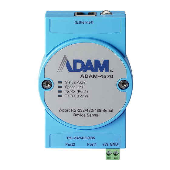
2.1.2 LED Indicators There are three or four LEDs located on the top panel of ADAM-4570 series, each with its own specific function. Table 2.1: ADAM-4570 Series LED Definition Color Status Description Heartbeat (1 time/sec) Not working Status/Power Power ON Green Power OFF 100 Mbps speed... -
Page 18: Dimensions (Unit: Mm)
2.1.3 Dimensions (Unit: mm) Figure 2.1: Top Panel Figure 2.2: Front Panel Figure 2.3: Back Panel ADAM-4570 Series User Manual... -
Page 19: Stickers
2.1.4 Stickers If you forgot the IP addresses of specific ADAM-4570 series or where the host PC is mapped to the ADAM-4570 series port, we have provided five stickers for you to note the IP addresses and place in a secure location. For example, 172.20.20.5: The IP address of specific ADAM-4570 series 160.59.20.89: The IP address of the specific host PC mapped to this port. -
Page 20: Figure 2.4:Panel Mounting
Panel Mounting The ADAM-4570 series can be attached to a wall using the included metal brackets. Each bracket comes with four screws; first attach the brackets to the bottom of the ADAM-4570 series. Next, screw each bracket to a wall. Figure 2.4: Panel Mounting ADAM-4570 Series User Manual... -
Page 21: Figure 2.5:Din-Rail Mounting
DIN-rail Mounting You can mount the ADAM-4570 series on a standard DIN-rail. First, using two screws, attach the metal plate to the DIN-rail bracket. Because the screw heads are beveled, the tops of the screws will be flush with the metal plate. -
Page 22: Figure 2.6:Piggyback Stack
Piggyback Stack ADAM-4570 series can be stacked as seen in the figure below. Figure 2.6: Piggyback Stack ADAM-4570 Series User Manual... -
Page 23: Network Connection
2.2.2 Network Connection There are two ways to use the 10/100Base-T Ethernet connector located on the ADAM-4570 series: 1. For Local Area Network (LAN) applications using the ADAM-4570 series, you will simply plug one end of your Ethernet cable into the 10/100Base-T connector, and the other end into the hub con- nected to your network. -
Page 24: Power Connection
2.2.3 Power Connection You should take the following steps to connect ADAM-4570 series power. 1. Connect the power cable to 2-pin connector 2. Connect power cable to power adapter Figure 2.8: Power Connection If the ADAM-4570 Series is working properly, the green power LED will light up, indicating that the ADAM-4570 Series is receiving power. - Page 25 RJ-48 PIN Name RTS CTS RI RJ-48 DB-9 Chapter 2...
-
Page 26: Configuration Utility Installation
Be sure that you have at least version 2.0 of the Note: Microsoft .NET Framework installed on your PC. 1. Insert the Advantech IEDG series driver utility CD-ROM into the drive (e.g. D:\) on the host PC. Change the host computer's default drive from C: to D: 2. - Page 27 4. Carefully read the Software License Agreement, and press "Yes" to continue. 5. The Setup program will specify a default installation path: Advantech eAutomation\Serial Device Server Configuration Utility\ 6. In this step, you may select a specific program folder or just use the default setting and press "Next".
- Page 28 7. After setup has copied all program files to your computer, click the <Finish> button to finish the installation. ADAM-4570 Series User Manual...
- Page 29 Configuration...
-
Page 30: Chapter 3 Configuration
PC to enhance network security. With this secure function enabled, other PCs will not have permission for configuration. After the installation program on the Advantech IEDG Series Driver Utility CD-ROM is finished, the serial device servers will be ready for use and configure. - Page 31 Area, the configuration page will display on the area. Quick Tool Bar: Useful management functions shortcut. Note: Please reserve TCP/UDP port 5048 and 5058 in your Ethernet network, configuration utility will use these ports to communicate with Advantech EKI-1000, EDG-4500, and ADAM-4570 serial device servers. Chapter 3...
-
Page 32: Discovering Your Serial Device Server
3.2 Discovering Your Serial Device Server 3.2.1 Auto Searching Advantech Serial Device Server Configuration Utility will automatically search all the EKI-1000, EDG-4500, and ADAM-4570 series device servers on the network and show them on the Serial Device Server List Area of the utility. The utility provides an auto-search function to show your device(s) by simply executing the configuration utility program from the Start Menu. - Page 33 Note When you run the Configuration Utility for the first time, the default device name is "MAC ID". In this case, the device name "ADAM-4571L-A6A1DB" means the device "MAC ID" is "00 D0 C9 A6 A1 DB". You can change the default device name in System Tab of Device Properties.
- Page 34 Click on each item, you will entry the configuration page to change the setting. The configuration will be introduced on following sections. ADAM-4570 Series User Manual...
-
Page 35: Clearing The Device List And Searching Again
3.2.2 Clearing the Device List and Searching Again You can click the button on the “Quick Tool Bar”; utility will clear all list device servers in the Serial Device Server List Area and re-search again. Don’t use this function frequently. The warning message will be pop-up when you double click this button. -
Page 36: Manual Appending
3.2.3 Manual Appending Using “Add IP address to Favorite” or “Search a Range of IP addresses” function, you are able to add one device or group of devices to “Favorites”. These devices can locate on local network domain or other network domain. -
Page 37: Setting Ethernet Parameters
IP Address, Subnet Mask, Default Gateway: The IP address identifies your Advantech serial device server on the glo- bal network. Each ADAM-4570 series has the same default IP address 10.0.0.1. Obtain these specific IP addresses from your network adminis- trator and then configure each Advantech serial device server with indi- vidual IP addresses, related Subnet Mask and Gateway Setting. -
Page 38: Setting Serial Parameters
Note When you have finished the configuration of these set- tings for each category, please press the “Apply” button in order to make these settings effective on the Serial Device Server. (Will reboot your Serial Device Server) Note ADAM-4570 series serial device severs do not support DHCP and Auto IP functions. -
Page 39: Basic Configuration
3.4.1 Basic Configuration Description: You can give a more detailed description on the function of the port for easier management and maintenance. Descriptions have a limit of 128 characters. Baud Rate: The ADAM-4570 series supports baud rate from 50 to 921.6Kbps. While setting the baud rate, please note that the value should conform to the cur- rent transmission speeds of connected devices. - Page 40 Data Bits: The ADAM-4570 series provides four options: 5, 6, 7 and 8. Stop Bits: The ADAM-4570 series provides three options: 1, 1.5 and 2. Flow Control: The ADAM-4570 series provides four options: None, XOn/XOff, RTS/ CTS, and DTR/DSR. ADAM-4570 Series User Manual...
-
Page 41: Operation Mode Configuration
Window 2000/XP/Vista(X86) systems. The driver establishes a transparent connection between host and serial device by mapping the IP of Advantech serial device server serial port to a local COM port on the host computer. The ADAM-4570 series provides Multi-access function through Ethernet connection path. - Page 42 Host Idle Timeout (10 to 255 seconds): The "Host Idle Timeout" setting monitors the connection between the host and the device. If the "Host Idle Timeout" setting time is reached, the device server will release the resources allocated to the port mapping. This prevents a stalled host from affecting the connective device.
-
Page 43: Data Mode (Usdg Mode)
3.4.3 Data Mode (USDG Mode) (Only ADAM-4571 and ADAM-4570 support this function) The ADAM-4571/4570 can be Data Server or Data Client either. Both operations support TCP and UDP protocol. The ADAM-4571/4570 makes your serial devices behave just like networking devices. You can issue commands or transmit data from serial devices, which connected to the ADAM-4571/4570, to any devices that are connected to the Internet. - Page 44 Telnet connections. There are also custom sockets that users and develop- ers define for their specific needs. The default TCP/UDP port of the ADAM-4571/4570 is 5300. The example initial 5300 is System Port, and 5301 is Data Port. But users can adjust them by one's preference or appli- cation.
- Page 45 The default is 60 seconds. If you want to keep connection continually, you can disable the Data Idle Timeout. Data idle Time is the time period in which the device waits for data. If the ADAM-4571/4570 does not receive data over an established idle time, the ADAM-4571/4570 will disconnect temporarily.
- Page 46 Frame Break function, the ADAM-4571/4570 will wait “Response Time- out” period, whether the device have transmitted the data. During this period, the commands from hosts will be queued and the ADAM-4571/ 4570 just processes this command. Enabling “Frame Break”, if the serial port idle is longer than the “Frame Break”...
-
Page 47: Control Mode (Usdg Mode)
The “Control mode” provides three kinds of modem AT-style commands. The serial devices can use these commands to control the ADAM-4571/ 4570 to connect/disconnect to remote networking device. Thus, intelli- gent serial devices such as standalone PLC will send /receive data to/from devices one by one via Ethernet. - Page 48 Hangup Character The default character is “+”. After you have connected to another serial device via ADAM-4571/4570, you may need to disconnect. Then you can use the command "+++" to disconnect. To do this leaves your keyboard idle (don't press any keys) for at least several seconds, then press "+"...
-
Page 49: At Command List
ATDT<IP “Forms a TCP connection to the specified host. address> Ex: ATDT 192.0.55.22:5201 <TCP port> In above example, the ADAM-4571/4570 serial <CR> device server forms a raw TCP connection to the networking device (192.0.55.22). The TCP port is 5301.” ATA <CR>... -
Page 50: Advanced Settings
3.4.6 Advanced Settings The serial device server provides the advanced settings for some special applications which need critical time requirements. In normal applica- tions, these settings are recommended not to be set to avoid the unusual action happened. Delay Time (ms) When enabled, the serial port will postpone the received data for the time interval you set, and then send the received data to the TCP/IP network. -
Page 51: Security Configuration
3.5 Security Configuration 3.5.1 Accessible Function Allow any IP to access: The default option, any host PC can communicate with this serial device server. Specified IP which can access: Type the IP address in the column and click “Add” or “Delete” button to make the accessible IP address list. -
Page 52: Port Monitor
3.5.2 Port Monitor Configuration utility provides an excellent function that allows monitor- ing the serial ports’ status. It will present each serial port’s operation mode and status. The IP address of Host PC which is communicating with serial port will be list on the right window. Click “Refresh” button, the status will be refresh once. -
Page 53: Fulfilling Administrator Functions
3.6 Fulfilling Administrator Functions The configuration utility provides several administrator settings for easy management and configuration. Right click the mouse on the device name in the sub-tree of Serial Device Sever List Area, and select these administrator settings. 3.6.1 Import/Export Serial Port Setting The utility allows importing or exporting the serial port setting including “Basic Setting”... -
Page 54: Locate Serial Device
3.6.2 Locate Serial Device If there are many serial device servers need your management, you may need to identify which unit is correct to configuration on utility. Click “Locate” to make that unit’s “Status” LED be steady on until you click “Stop Locate”. -
Page 55: Restore To Factory Default Settings
If you want to disable this function or change the password, click “Change Password” to change the password to default “None” (leave the new password and confirm new password columns blank) to disable this function or other password you want to change. Be sure to click “Reset Device”... -
Page 56: Upgrading The Firmware
3.6.5 Upgrading the Firmware Advantech continually upgrades its firmware to keep up with the ever- expanding world of computing. You can use the update firmware function in the utility to carry out the upgrade procedure. Please access Advantech’s Website at... - Page 57 Select the firmware you want to update. After downloading the firmware completely, click on the “OK” button. The serial device server will restart automatically. Note: Be sure that the host PC Ethernet network domain is as same as the ADAM-4570 series device server while doing the updating firmware process.
- Page 58 ADAM-4570 Series User Manual...
- Page 59 Setting the COM Redirector...
-
Page 60: Chapter 4 Setting The Com Redirector
Windows COM ports. 4.1 Setting COM Redirector (Virtual COM port) Advantech COM port mapping software is a serial COM port redirector that creates virtual COM ports and provides access to serial devices con- nected to Advantech serial device servers. Your serial device applications can communicate with serial devices connected to Advantech serial device servers without software changes. - Page 61 The serial ports that can be assigned to virtual COM will be shown in this window. Select the serial ports you wish to map or click the <Select All> button and press <Map Selected Ports> button. The selected serial ports will be mapped to virtual COM ports in sequential order.
-
Page 62: Manual Mapping
4.1.2 Manual Mapping Right click the serial device name on the sub-tree of Device Server List area and select the “Manual Mapping” function. ADAM-4570 series have only one IP address. You select the serial port on the device server and the host COM that you want to set. Press <Map it>... -
Page 63: Manual Direct Mapping Virtual Com Port
Sometimes, the connection between Advantech serial device server and HOST is interrupted by network traffic or powered-off by accident. In such a situation, the host has to reconnect to Advantech serial device server. The function "Auto Reconnect" is for this purpose, if the Advantech serial device server loses the connection to its host, the COM redirector will try to re-establish the connection while the host’s AP... -
Page 64: Remove The Virtual Com Port
4.1.4 Remove the Virtual COM Port If you want to remove the virtual COM port, you can remove them one by one or group remove ports. Individually Remove Right click on COM port you have mapped before and select “Remove This Port”. -
Page 65: Running Diagnostic Test
4.2 Running Diagnostic Test The purpose of this test is to make sure the communication from host PC to ADAM-4570 series is OK. If there is still an error, you can check the communication from the ADAM-4570 series to the devices. If the test is selected, an external test will be done to check that the connection signals for each port are working properly. - Page 66 Click “Simple Serial Test” on the Tools menu. Select which COM port you want to run diagnostic test, and then press “Test” button to process the testing. ADAM-4570 Series User Manual...
- Page 67 Signal Test • RTS -> CTS check the RTS and CTS signal between two ports • DTR -> RI check the DTR and RI signal between two ports • DTR -> DSR check the DTR and DSR signal between two ports •...
- Page 68 ADAM-4570 Series User Manual...
- Page 69 Pin Assignments...
-
Page 70: Appendix A Pin Assignments
Appendix A Pin Assignments A.1 RS-232 Pin Assignments A.2 RJ-48 Cable PIN Assignment A.2.1 1. RS-422 Pin No. Description A.2.2 2. RS-485 Pin No. Description Data- Data+ ADAM-4570 Series User Manual...
Need help?
Do you have a question about the ADAM-4571 and is the answer not in the manual?
Questions and answers