Advertisement
Quick Links
Download this manual
See also:
Service Manual
Advertisement

Related Manuals for Fargo hdp8500


Summary of Contents for Fargo hdp8500
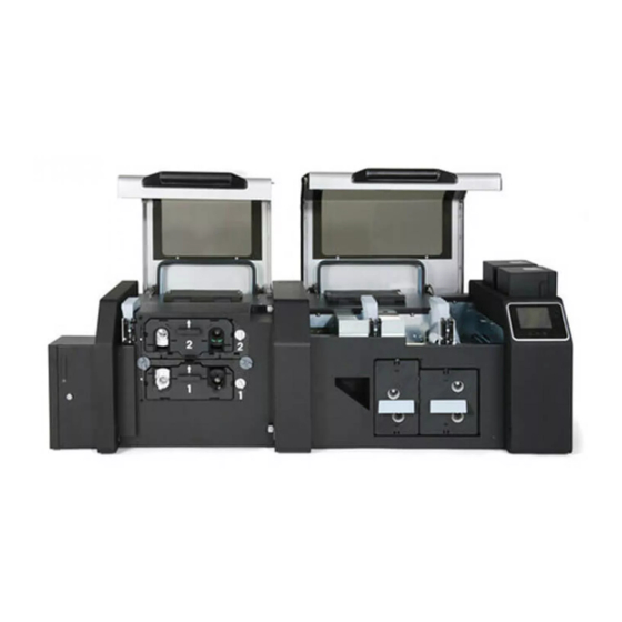
- Page 1 15370 Barranca Parkway Irvine, CA 92618 FARGO ® HDP8500 Card Printer PRINTHEAD REPLACEMENT GUIDE PLT-01638, 1.1 November 2013 © 2013 HID Global Corporation/ASSA ABLOY AB. All rights reserved.
-
Page 2: Liability Statement
HID Global Corporation without notice. Trademarks HID GLOBAL, HID, the HID logo, HDP and FARGO are the trademarks or registered trademarks of HID Global Corporation or its licensors in the U.S. and other countries. - Page 3 HDP8500 Printhead Replacement Guide L001638 rev 1.1 User Contacts North America Europe, Middle East and Africa 15370 Barranca Parkway Phoenix Road Irvine, CA 92618 Haverhill, Suffolk CB9 7AE England Phone: 800 237 7769 Phone: +44 1440 714 850 Fax: 949 732 2120...
-
Page 4: Safety Messages (Review Carefully)
HDP8500 Printhead Replacement Guide L001638 rev 1.1 User Safety Messages (review carefully) The purpose of this section is to provide the User with specific replacement procedures for the Card Printer. Please review standard precautions (to take) while performing these replacement procedures. -
Page 5: Installing The Printhead
HDP8500 Printhead Replacement Guide L001638 rev 1.1 User Installing the Printhead Kit Part Number: 088934 Tools needed: T10 (Torx )Driver Estimated Repair Time: 30 minutes Important: This procedure can only be performed by authorized service personnel. Step Procedure Caution: Power off the Printer by unplugging the power cord from the Printer. - Page 6 HDP8500 Printhead Replacement Guide L001638 rev 1.1 User Step Procedure Unplug the RTD Wire Cable, Heater Wire Cable, and Interconnect Cable ( with small com board D940171) from the Auxiliary Board (A920221-10). Remove the 3 screws holding the Auxiliary Board (A920221-10) to the frame.
- Page 7 HDP8500 Printhead Replacement Guide L001638 rev 1.1 User Step Procedure Remove the Ethernet/USB box. Remove two screws from the BOX base. Pull the box forward and slide to the RIGHT then OUT. Doing this will release the box from the PCB board (Ethernet/ USB Connection ) directly behind the box.
- Page 8 HDP8500 Printhead Replacement Guide L001638 rev 1.1 User Step Procedure Gently pull the hoses from the Printer. Disconnect the 2 Fan Cable from the Fan Box. Disconnect the MAG wires from the back of the Fan Box. © 2013 HID Global Corporation/ASSA ABLOY AB. All rights reserved.
- Page 9 HDP8500 Printhead Replacement Guide L001638 rev 1.1 User Step Procedure Disconnect the wires from the tie wrap on the Fan Box. Disconnect the Ribbon Cable from the D000445 Board ( attached to the Fan Box Riser) Set aside the Fan Box and Fan Box Riser.
- Page 10 HDP8500 Printhead Replacement Guide L001638 rev 1.1 User Step Procedure The Printhead Motor Mount (D910052) is now accessible. Remove the Printhead Motor Mount (D910052). Remove the one (1) screw that holds the Motor Mount to the Frame, as shown below. (Note: The Mount should be “flush” with the Frame when properly fitted.)
- Page 11 HDP8500 Printhead Replacement Guide L001638 rev 1.1 User Step Procedure Remove the ground strap of the Printhead. Unplug the Printhead Motor Mount Connectors. © 2013 HID Global Corporation/ASSA ABLOY AB. All rights reserved.
- Page 12 HDP8500 Printhead Replacement Guide L001638 rev 1.1 User Step Procedure Lift out the Printhead Motor Mount assembly. Carefully lift out the complete Printhead Assembly (D910515). © 2013 HID Global Corporation/ASSA ABLOY AB. All rights reserved.
- Page 13 HDP8500 Printhead Replacement Guide L001638 rev 1.1 User Step Procedure Complete the replacement by doing the following steps. See below for details. a. Replace the complete Printhead Assembly. IMPORTANT NOTE: Locate the Printhead Resistance value stamped on the printhead BEFORE installing. This VALUE is needed for step 26 b.
- Page 14 HDP8500 Printhead Replacement Guide L001638 rev 1.1 User Note how the Print Platen Roller Slot would fit properly onto the Roller bushing, as shown from the back side (below). © 2013 HID Global Corporation/ASSA ABLOY AB. All rights reserved.
- Page 15 HDP8500 Printhead Replacement Guide L001638 rev 1.1 User Step Procedure Careful when replacing the Printhead Motor Mount (D910052) Replace Fan Box and all cables, Ethernet/USB Box, and Auxiliary Board. Replace Covers in reverse assembly. You have completed this procedure. Open the Driver Toolbox then Advanced Settings. Change/verify the Printhead Resistance value.
Need help?
Do you have a question about the hdp8500 and is the answer not in the manual?
Questions and answers