Table of Contents
Advertisement
Quick Links
WARNING:
If the information in these instructions is not followed exactly, a fire or explosion may result
causing property damage, personal injury or loss of life.
•
DO NOT PLACE ARTICLES ON OR AGAINST THIS APPLIANCE.
•
DO NOT USE OR STORE FLAMMABLE MATERIALS NEAR THIS APPLIANCE.
•
DO NOT SPRAY AEROSOLS IN THE VICINITY OF THIS APPLIANCE WHILE IT IS IN OPERATION.
•
DO NOT MODIFY THIS APPLIANCE.
-
Do not store or use gasoline or other flammable vapors and liquids in the vicinity of this or any other appliance.
WHAT TO DO IF YOU SMELL GAS
• Do not try to light any appliance.
• Do not touch any electrical switch; do not use any phone in your building.
• Immediately call gas supplier from a neighbor's phone. Follow the gas supplier's instructions.
• If you cannot reach your gas supplier, call the fire department.
-
Installation and service must be performed by a qualified installer, service agency or the gas supplier.
This appliance may be installed in
an aftermarket permanently
located, manufactured home (USA
only) or mobile home, where not
prohibited by local codes.
This appliance is only for use
with the type(s) of gas indicated
on the rating plate. A conversion
kit is supplied with the appliance.
Installation Manual
Installer:
After installation give this manual to the home-
owner and explain operation of this heater.
Copyright 2018, T.I.
42 & 54 Linear GSB2
$10.00
100-01474
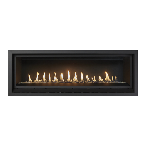
ProBuilder
• Direct Vent Fireplace
• Natural Gas or Propane
• Vent Horizontally or Vertically
• Standard Residential
• Mobile Home Approved
Listed by
AS/NZS 5263.1.3
GMK10166
IAPMO-R&T OCEANA
Dragon Wholesaling Pty. Ltd.
Unit 4, 16 Lexington Drive
Bella Vista NSW
3/13/18
Australia 2153
Advertisement
Table of Contents

Related Manuals for Travis Industries ProBuilder 42


Summary of Contents for Travis Industries ProBuilder 42
- Page 1 ProBuilder 42 & 54 Linear GSB2 • Direct Vent Fireplace • Natural Gas or Propane • Vent Horizontally or Vertically • Standard Residential • Mobile Home Approved Listed by AS/NZS 5263.1.3 GMK10166 IAPMO-R&T OCEANA WARNING: If the information in these instructions is not followed exactly, a fire or explosion may result causing property damage, personal injury or loss of life.
-
Page 2: O Verview
Introduction O verview This manual details the installation requirements for the ProBuilder Linear fireplace. For operating and maintenance instructions, refer to the ProBuilder Linear Owner's Manual. S afety Label © Travis Industries 3/13/18 - 1474 42 & 54PB GSB2 Aust. -
Page 3: Table Of Contents
Vent Configuration: Vertical Termination for 42 PB ONLY ................30 Vent Configuration: Horizontal Termination with Vertical Rise for 42 PB ONLY ..........31 Vent Configurations for 54 PB ONLY For 42 PB see page 29 ............... 32 © Travis Industries 3/13/18 - 1474 42 & 54PB GSB2 Aust. -
Page 4: Safety Warnings
Do not operate if any portion of the heater was submerged in water or if any corrosion occurs. Immediately call a qualified service technician to inspect the appliance and to replace any part of the control system and any gas control which has been under water. © Travis Industries 3/13/18 - 1474 42 & 54PB GSB2 Aust. - Page 5 It is imperative that control compartments, burners, and circulating air passageways of the appliance be kept clean. • Travis Industries, Inc. grants no warranty, implied or stated, for the installation or maintenance of your heater, and assumes no responsibility of any consequential damage(s). SAFETY WARNINGS: •...
-
Page 6: Installation Options
Approximate Heating Capacity (in square meters)* Up to 154 Up to 154 54 ProBuilder Maximum Input Per Hour (MJ/h) 34.81 34.81 Heating capacity will vary with floor plan, insulation, and outside temperature. Dimensions © Travis Industries 3/13/18 - 1474 42 & 54PB GSB2 Aust. -
Page 7: Packing List
• Install the drywall. • Install the hearth (if applicable). • Install the facing (if applicable). • Install the mantel (if applicable). • Finalize the installation (see page 42). © Travis Industries 3/13/18 - 1474 42 & 54PB GSB2 Aust. -
Page 8: Fireplace Placement Requirements
The top of the control door (firebox opening) is approximately 8-3/4” (223mm) above the base of the fireplace. For a typical raised fireplace of 36” (915mm), place the fireplace on a platform 27.25” (693mm) tall. © Travis Industries 3/13/18 - 1474 42 & 54PB GSB2 Aust. -
Page 9: Televisions Placed Above The Fireplace
The homeowner must understand that Travis Industries does not take responsibility for any negative impact to televisions placed near this fireplace. -
Page 10: Using A Buildout Above Fireplace And Television
The homeowner must understand that Travis Industries does not take responsibility for any negative impact to televisions placed near this fireplace. -
Page 11: Using A Buildout Below A Television
The homeowner must understand that Travis Industries does not take responsibility for any negative impact to televisions placed near this fireplace. -
Page 12: Minimum Framing Dimensions
Installation (for qualified installers only) Minimum Framing Dimensions The fireplace enclosure must be a minimum 45-1/4” (1150mm) tall. Do not build into the fireplace enclosure. © Travis Industries 3/13/18 - 1474 42 & 54PB GSB2 Aust. -
Page 13: Standoff Assembly
These standoffs, when properly constructed, provide a guide for the required 1/2" clearance. NOTE: The rear standoffs are bent around the rear corners of the fireplace as shown below to the right. © Travis Industries 3/13/18 - 1474 42 & 54PB GSB2 Aust. -
Page 14: Nailing Brackets
Use shims to insure the fireplace is square. NOTE: The nailing brackets have two positions: standard and extended. See the section “Facing Requirements” for details on which position is best for your installation. © Travis Industries 3/13/18 - 1474 42 & 54PB GSB2 Aust. -
Page 15: Standard Vs. Extended Position
If the unit is being installed in the extended position, the standoff/heat shield assembly must be repositioned back ½” (see illustration below). NOTE: see pages 14 & 38.for additional details about standard vs. extended installations. © Travis Industries 3/13/18 - 1474 42 & 54PB GSB2 Aust. -
Page 16: Header And Pipe Shield Installation
At each of the perforations, bend the sides of the pipe shield backwards 90° as shown below. NOTE: The bottom flanges should be facing outward Tabs face out. Bend at perforations © Travis Industries 3/13/18 - 1474 42 & 54PB GSB2 Aust. - Page 17 Remove the (4) screws, (2) from each side of the starter collar. Line up the holes on the pipe shield tabs with the holes from the screws you just removed. Use the screws to attach the pipe shield to the top of the fireplace. Remove screws © Travis Industries 3/13/18 - 1474 42 & 54PB GSB2 Aust.
- Page 18 Bend the legs at the perforations as shown below and attach the foot of the standoff to the top of the fireplace using the screw removed earlier in this step. Remove screw © Travis Industries 3/13/18 - 1474 42 & 54PB GSB2 Aust.
- Page 19 Bend tabs down 90° Align holes When finished the fireplace should be configured like the picture below. © Travis Industries 3/13/18 - 1474 42 & 54PB GSB2 Aust.
-
Page 20: Corner Installations
A typical 45° installation uses the framing dimensions shown in the illustration below (NOTE: all clearances still apply). 42PB 54PB (a) Corner to Wall (minimum) 53-1/2” 1359mm 63-3/4” 1619mm (b) Corner to Center of Flue (typical) 20-3/4” 528mm 25” 635mm © Travis Industries 3/13/18 - 1474 42 & 54PB GSB2 Aust. -
Page 21: Removing The Front Panel
To remove the front cover (a) Remove the center wingnuts. (b) Loosen the two outer screws. (c) Rotate the front panel down. (d) Remove the front cover. © Travis Industries 3/13/18 - 1474 42 & 54PB GSB2 Aust. -
Page 22: Gas Line Requirements
The supply regulator (the regulator that attaches directly to the residence inlet or to the propane tank) should supply gas at the suggested input pressure listed above. Contact the local gas supplier if the regulator is at an improper pressure. © Travis Industries 3/13/18 - 1474 42 & 54PB GSB2 Aust. -
Page 23: Gas Line Location
Remove the knock-out in the desired location (you may wish to remove both knockouts if routing electrical through the base as well). Route the flex gas line (with shutoff valve) to the desired location. © Travis Industries 3/13/18 - 1474 42 & 54PB GSB2 Aust. -
Page 24: Electrical Connection
Attach the junction box to the baseplate (make sure all wiring is kept from contacting hot or moving components). Attach the cover plate to the left side. © Travis Industries 3/13/18 - 1474 42 & 54PB GSB2 Aust. -
Page 25: Optional Wall Switch Or Thermostat Installation
Heater is OFF Heater is OFF Switch OFF External Switch OFF To wire the heater in parallel, follow the directions below: To wire the heater in series, follow the directions below: © Travis Industries 3/13/18 - 1474 42 & 54PB GSB2 Aust. -
Page 26: Vent Requirements
• Horizontal sections require a 1/4" (6mm) rise every 12" (305mm) of travel. • Horizontal sections require non-combustible support every three feet (e.g.: plumbing strap). © Travis Industries 3/13/18 - 1474 42 & 54PB GSB2 Aust. -
Page 27: Approved Vent Configurations
An exhaust restrictor is built into the appliance to adjust the flow rate of exhaust gases. Depending upon the vent configuration, you may be required to adjust the restrictor position. The charts for vent configurations detail the correct restrictor position. © Travis Industries 3/13/18 - 1474 42 & 54PB GSB2 Aust. -
Page 28: Diffuser
A diffuser is built into the appliance to adjust the flow rate of exhaust gases. Depending upon the vent configuration, you may be required to adjust the diffuser to the open position (see illustration below). The charts for vent configurations detail the correct diffuser position. © Travis Industries 3/13/18 - 1474 42 & 54PB GSB2 Aust. -
Page 29: Vent Configurations For 42 Pb Only For 54 Pb
• The termination must fall within the shaded area shown in the chart. Use the indicated restrictor positions. • One 45° elbow may be used on the horizontal run. • HINT: Use minimum vent kit “H” (96200332) from Travis Industries (additional vent may be required). Use the included wall thimble when penetrating a wall. -
Page 30: Vent Configuration: Vertical Termination For 42 Pb Only
• The termination must fall within the shaded area shown in the chart. Use the indicated restrictor positions. • Up to four elbows (45° or 90°) may be used. Only one horizontal elbow may be used. © Travis Industries 3/13/18 - 1474 42 & 54PB GSB2 Aust. -
Page 31: Vent Configuration: Horizontal Termination With Vertical Rise For 42 Pb Only
• The termination must fall within the shaded area shown in the chart. Use the indicated restrictor positions. • Up to four elbows (45° or 90°) may be used. Only one horizontal elbow may be used. © Travis Industries 3/13/18 - 1474 42 & 54PB GSB2 Aust. -
Page 32: Vent Configurations For 54 Pb Only For 42 Pb
• The termination must fall within the shaded area shown in the chart. Use the indicated restrictor positions. • One 45° elbow may be used on the horizontal run. • HINT: Use minimum vent kit “H” (96200332) from Travis Industries (additional vent may be required). Use the included wall thimble when penetrating a wall. -
Page 33: Vent Configuration: Vertical Termination For 54 Pb Only
• The termination must fall within the shaded area shown in the chart. Use the indicated restrictor positions. • Up to four elbows (45° or 90°) may be used. Only one horizontal elbow may be used. © Travis Industries 3/13/18 - 1474 42 & 54PB GSB2 Aust. -
Page 34: Vent Configuration: Horizontal Termination With Vertical Rise For 54 Pb Only
• The termination must fall within the shaded area shown in the chart. Use the indicated restrictor positions. • Up to four elbows (45° or 90°) may be used. Only one horizontal elbow may be used. © Travis Industries 3/13/18 - 1474 42 & 54PB GSB2 Aust. -
Page 35: Termination Requirements
NOTE: Clearance in accordance with local installation codes and the requirements of the gas supplier. Minimum 12” (305mm) above the roof line (for vertical terminations) Minimum 24” (610mm) horizontal clearance to any surface (such as an exterior wall) – for vertical terminations © Travis Industries 3/13/18 - 1474 42 & 54PB GSB2 Aust. -
Page 36: Hearth Requirements
• A non-combustible hearth may be constructed in front of the fireplace (see illustration below). © Travis Industries 3/13/18 - 1474 42 & 54PB GSB2 Aust. -
Page 37: Facing Requirements
NOTE: Screws may be used to secure cement board or tile backer to the fireplace. Do not penetrate the fireplace more than 1/2” (13mm). © Travis Industries 3/13/18 - 1474 42 & 54PB GSB2 Aust. -
Page 38: Standard Vs. Extended Position
(the header shield is also moved). Most installations use the standard nailing bracket position. If using a facing that does not use a backing board (e.g. marble), you may wish to use the extended position. © Travis Industries 3/13/18 - 1474 42 & 54PB GSB2 Aust. -
Page 39: Facing Thicker Than 1-1/2" (38Mm)
1/8” (3.2mm) gap to the sides and below. UNIFORM GAP 3/4" (19mm) 7/8” (22.5mm) 5/8” (16mm) This provides 3/8” (9.5mm) gap around all sides of the screen assembly. © Travis Industries 3/13/18 - 1474 42 & 54PB GSB2 Aust. -
Page 40: Screen Assembly Mounts
To adjust the mounts, loosen the screws, slide the mounts to the desired position, then tighten the screws. Position edge of mount flush with finish material © Travis Industries 3/13/18 - 1474 42 & 54PB GSB2 Aust. -
Page 41: Do Not Drill Or Screw Zone
“DO NOT DRILL” shading. Make sure screws penetrate no more than ½” (13mm) into the fireplace. Do not drill or screw in the marked area © Travis Industries 3/13/18 - 1474 42 & 54PB GSB2 Aust. -
Page 42: Mantel Requirements
Combustible mantel columns (legs) require a 0” (0mm) clearance to the side of the fireplace (they must be to the side of the fireplace). • Non-combustible mantel columns do not have a minimum clearance. © Travis Industries 3/13/18 - 1474 42 & 54PB GSB2 Aust. -
Page 43: Mantel Clearances
The facing must be non-combustible and extend to the header (or mantel, whichever is greater). The facing must also span the entire width of the mantel. • See the illustration below for additional requirements. © Travis Industries 3/13/18 - 1474 42 & 54PB GSB2 Aust. -
Page 44: Finalizing The Installation
Pilot Hood Sensing Spark electrode Electrode 4. Replace the glass. 5. Start the main burner and verify the burner ignites correctly. 6. Leak test all gas joints. © Travis Industries 3/13/18 - 1474 42 & 54PB GSB2 Aust. -
Page 45: Air Shutter Adjustment
ACID WASH WARNING: Make sure any masonry that has been treated with acid wash has been properly neutralized (this is used primarily with brick faces). Acid wash (muriatic acid) is used to remove excess mortar. © Travis Industries 3/13/18 - 1474... -
Page 46: Location Of Controls
There is a door on the lower portion of the screen assembly to provide access to the manual controls on the fireplace. The door is held closed by two magnets. Open the door by gently pulling outward on the upper portion of the lower trim. © Travis Industries 3/13/18 - 1474 42 & 54PB GSB2 Aust. -
Page 47: Glass Frame Removal And Installation
Bottom Corner Top Corner Top hook engages Bottom hook this slot in bracket engages this slot in bracket Replacement Barrier Part # 42 ProBuilder 250-04494 54 ProBuilder 270-01993 © Travis Industries 3/13/18 - 1474 42 & 54PB GSB2 Aust. - Page 48 NOTE: Make sure the glass frame is all the way in place – It should be parallel with the front of the fireplace when installed. Replacement Glass Frame Part # 42 ProBuilder 250-04491 54 ProBuilder 270-01994 © Travis Industries 3/13/18 - 1474 42 & 54PB GSB2 Aust.
- Page 49 The latch can come loose from glass frame anchor. This occurs when it is turned 1/4 turn when it is disengaged. Follow the directions below to re-install the latch if it becomes loose. © Travis Industries 3/13/18 - 1474 42 & 54PB GSB2 Aust.
-
Page 50: Crushed Glass Installation
2 layers thick on the media tray. Make sure no glass is in the pilot area indicated in the picture below. No glass in this area. © Travis Industries 3/15/18 - 1474 42 & 54PB GSB2 Aust. - Page 51 Make sure the glass is only 1 layer deep on the burner. Only one layer thick on burner Remove the pilot shield to uncover the pilot once you are finished placing the glass. © Travis Industries 3/13/18 - 1474 42 & 54PB GSB2 Aust.
-
Page 52: Lp Conversion Instructions
2. Remove the burner skirt by lifting the front edge up and sliding the skirt forward. 3. Remove the media tray. Remove the 9 screws holding it in place (1/4” nutdriver). NOTE: The 54PB has 11 screws to remove, © Travis Industries 3/13/18 - 1474 42 & 54PB GSB2 Aust. - Page 53 4. Remove the burner. It is held in place with 8 screws (1/4” nutdriver). 5. Remove the air shutter retainer as shown below. It is held in place with 2 screws (1/4” nutdriver). © Travis Industries 3/13/18 - 1474 42 & 54PB GSB2 Aust.
- Page 54 6. Follow the directions below to replace the orifice. 7. Reinstall the orifice gasket that was removed in step 6. The longer portion of the gasket should be at the bottom. © Travis Industries 3/13/18 - 1474 42 & 54PB GSB2 Aust.
- Page 55 (b) Remove and discard the Natural Gas (NG) orifice. Place the LP orifice in the pilot assembly then replace the pilot hood, tightening the pilot hood until it is snug (do not over-tighten). © Travis Industries 3/13/18 - 1474 42 & 54PB GSB2 Aust.
- Page 56 There is a label on the base of the regulator knob indicating regulator type (NG or LP). Place the included label on the valve body where it can be easily seen to insure proper identification (“d”). © Travis Industries 3/13/18 - 1474 42 & 54PB GSB2 Aust.
-
Page 57: Wall Mount Remote Thermostat Installation
Remove the switch from the dashboard by depressing the tabs on the top and the bottom of the switch housing while pressing the back of the switch forward through the hole in the dashboard. Replace the switch with the included switch blank (see pictures below). © Travis Industries 3/13/18 - 1474 42 & 54PB GSB2 Aust. - Page 58 Discard the battery holder. Disconnect Run the end of the included wire harness with (4) wires to the control module. Insert the connector into the “X8 User Interface” location on the module. © Travis Industries 3/13/18 - 1474 42 & 54PB GSB2 Aust.
- Page 59 12 Align the two holes on the bottom of the receiver assembly with the studs and secure the assembly to the bracket using the two wing nuts removed in the previous step. © Travis Industries 3/13/18 - 1474 42 & 54PB GSB2 Aust.
- Page 60 16 Install the included (3) AAA batteries into the transmitter. 17 See operating instructions for instructions on how to synchronize the transmitter to the control module. 18 Return the appliance to the correct configuration. © Travis Industries 3/13/18 - 1474 42 & 54PB GSB2 Aust.
-
Page 61: Wiring Diagram - Gsb2 Version
Label all wires prior to disconnection when servicing controls. Wiring errors can cause improper and dangerous operation. 240 VAC Power In NOTE: IPI/CPI Switch may not be available in Australia © Travis Industries 3/13/18 - 1474 42 & 54PB GSB2 Aust. - Page 62 Installation Options ..........6 Vent Installation ..........26 Listing Details ............. 2 Vent Requirements .......... 26 Location of Controls ......... 46 Wiring Diagram ..........61 LP Conversion Instructions ......52 © Travis Industries 3/13/18 - 1474 42 & 54PB GSB2 Aust.
Need help?
Do you have a question about the ProBuilder 42 and is the answer not in the manual?
Questions and answers