Travis Industries 430 GSR2 Owner's Manual
With screen
Hide thumbs
Also See for 430 GSR2:
- Installation instructions manual (13 pages) ,
- Installation instructions manual (18 pages)
Table of Contents
Advertisement
WARNING:
If the information in these instructions is not followed exactly, a fire or explosion may result
causing property damage, personal injury or loss of life.
- Do not store or use gasoline or other flammable vapors and liquids in the vicinity of this or any
other appliance.
- WHAT TO DO IF YOU SMELL GAS
• Do not try to light any appliance.
• Do not touch any electrical switch; do not use any phone in your building.
• Immediately call your gas supplier from a neighbor's phone. Follow the gas supplier's
instructions.
• If you cannot reach your gas supplier, call the fire department.
- Installation and service must be performed by a qualified installer, service agency or the gas supplier.
A barrier designed to reduce the risk of burns from
the hot viewing glass is provided with this appliance
and shall be installed for the protection of children
and other at-risk individuals.
This appliance may be installed in an aftermarket, permanently located, manufactured home
(USA only) or mobile home, where not prohibited by local codes.
This appliance is only for use with the type of gas indicated on the rating plate. A conversion
kit is supplied with the appliance.
INSTALLER: Leave this manual with the appliance.
CONSUMER: Retain this manual for future reference.
Travis Industries, Inc.
Copyright 2014, T.I.
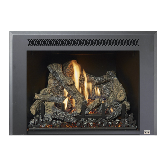
430 GSR2 Insert
(with screen)
Owner's Manual
HOT GLASS WILL CAUSE
BURNS
DO NOT TOUCH GLASS
UNTIL COOLED
NEVER ALLOW CHILDREN
TO TOUCH GLASS
12521 Harbour Reach Dr., Mukilteo, WA 98275
$10.00
Direct Vent Fireplace Insert
Masonry or Factory-Built
Residential or Mobile Home
4140811
Tested and Listed by
ANSI Z21.88-2014
CSA 2.33-2014
(Metal) Wood-Burning
Fireplace
www.travisproducts.com
100-01340
Advertisement
Table of Contents

Subscribe to Our Youtube Channel
Related Manuals for Travis Industries 430 GSR2


Summary of Contents for Travis Industries 430 GSR2
- Page 1 430 GSR2 Insert (with screen) Owner’s Manual WARNING: If the information in these instructions is not followed exactly, a fire or explosion may result causing property damage, personal injury or loss of life. - Do not store or use gasoline or other flammable vapors and liquids in the vicinity of this or any other appliance.
-
Page 2: Introduction
Introduction Introduction We welcome you as a new owner of a 430 GSR2 Insert. In purchasing this fireplace insert you have joined the growing ranks of concerned individuals whose selection of an energy system reflects both a concern for the environment and aesthetics. It is one of the finest home heaters the world over. This manual will explain the installation, operation, and maintenance of this heater. -
Page 3: Table Of Contents
Air Shutter Adjustment ........25 Burner Removal ..........26 IF WARRANTY SERVICE IS NEEDED: ..45 Before You Begin ........... 29 LP Conversion Instructions ......46 Remote Control Warnings ......29 © Travis Industries 4140811 100-01340... - Page 4 Do not operate if any portion of the heater was submerged in water or if any corrosion occurs. Immediately call a qualified service technician to inspect the appliance and to replace any part of the control system and any gas control which has been under water. © Travis Industries 4140811 100-01340...
- Page 5 Travis Industries, Inc. grants no warranty, implied or stated, for the installation or maintenance of your heater, and assumes no responsibility of any consequential damage(s).
-
Page 6: Features
This heater is shipped in natural gas (NG) configuration but may be converted to propane (LP) using the LP Conversion Kit (included) and the LP stepper motor (SKU 94400999, sold separately). The sticker on top of the gas control valve will verify the correct fuel. © Travis Industries 4140811 100-01340... -
Page 7: Installation Warnings
7. Replace the burner. 8. Install the media (logs, stones - see instructions included with the media). 9. Install the surround panel (see instructions included with surround panel). 10. Follow the instructions under “Finalizing the Installation.” © Travis Industries 4140811 100-01340... -
Page 8: Fireplace Requirements
You may wish to place it in a location where it will be covered by the surround panels. Fireplace Clearances to Gas Insert Side of Insert to Inside of Fireplace ½” (13mm) Back of Insert to Inside of Fireplace ½” (13mm) Top of Insert to Inside of Fireplace 3/4” (19mm) © Travis Industries 4140811 100-01340... -
Page 9: Factory-Built (Metal) Wood-Burning Fireplace Requirements
½” of non-combustible material must extend 1.75” (45mm) in front of the insert for the full width of the unit (29.5” / 750mm). RAISED INSERTS: If the insert is raised a minimum of 16” above the flooring (or other combustible material), a non-combustible hearth is not required in front of the insert. © Travis Industries 4140811 100-01340... -
Page 10: Leveling Bolts
1. Remove the cover and gasket to access the rear leveling bolt. Replace after adjustment. Electrical Requirements Travis Industries manufactures a wiring kit specifically for inserts (sku 97200315). This kit allows installers to wire 120 volt AC power into a fireplace directly to the insert, eliminating the need for an external power cord. -
Page 11: Clearances
If it does, it is considered a mantel and must meet the mantel requirements listed in this manual. Maximum Mantel Depth 35"(889mm) 34"(864mm) 33"(839mm) Mantel Height 32"(813mm) Above B as e of Ins ert (n) 31"(788mm) © Travis Industries 4140811 100-01340... -
Page 12: Gas Line Requirements
5/16” i.d. rubber or plastic tubing over the tapered test port. Connect the tubing to the test gauge. WARNING: The brass screw must be tightened after testing to prevent gas leakage. Output pressure Input pressure © Travis Industries 4140811 100-01340... -
Page 13: Gas Line Installation
3. Attach the included gas shutoff valve to the end of the flex tube and gas inlet as shown below. Position so the valve handle is on the right as shown. Leak-test all gas line connections. © Travis Industries 4140811 100-01340... -
Page 14: Vent Requirements
Installation (for qualified installers only) Vent Requirements Travis Industries manufactures a vent kit specifically for this insert (sku 96200330). It includes 30’ (10M) of vent, hose clamps, and a prairie cap. The flashing on the cap is 18” (458mm) by 18” (458mm). -
Page 15: Exhaust Restrictor
Restrictor Settings Traditional Logs Natural Gas Short Vent (25’ or less) #3 (stock position) Natural Gas Tall Vent (25’ or more) Propane Short Vent (25’ or less) Propane Tall Vent (25’ or more) # 3 (stock) © Travis Industries 4140811 100-01340... -
Page 16: Adjusting The Exhaust Restrictor
Slide the restrictor plate to the correct position (b). Once in place, tighten the screws to secure the restrictor plate in position (c). In the example pictured, the restrictor is in position # 4. © Travis Industries 4140811 100-01340... -
Page 17: Diffuser Adjustment
The diffuser must be adjusted before attaching the vent (it is attached to the vent connector and is concealed once the vent is installed). Use a screwdriver or pliers to bend the diffuser to a vertical position. Diffuser Open Diffuser Closed (stock) © Travis Industries 4140811 100-01340... -
Page 18: Vent Installation
Block-Off Plate (non-combustible materials) Inlet Mas onry F ireplac e Z.C . (Metal) Wood-B urning F ireplac e NOTE: You may use either re-line configuration with a masonry or zero-clearance fireplace. © Travis Industries 4140811 100-01340... -
Page 19: Vent Attachment - Tight Installations
4. Slide the insert into place, guiding the vent connector into the guides on top of the insert. 5. Attach the vent connector to the appliance (see the following page for details). 6. Remove any excess slack in the flex line and attach the vent termination. © Travis Industries 4140811 100-01340... -
Page 20: Vent Connector Attachment
Finalizing the Installation Vent Connector Attachment 1. Remove the exhaust restrictor to access the vent connector. 2. Remove these 2 nuts using a 3/8” nutdriver. 3. Tilt and remove the vent connector. © Travis Industries 4140811 100-01340... - Page 21 4. Make sure the gasket remains in place. Use silicone, if necessary, to secure the gasket. 5. Attach the 3” exhaust vent to the connector and secure with at least 3 screws. 6. Attach the 3” intake vent to the connector and secure with at least 3 screws. © Travis Industries 4140811 100-01340...
- Page 22 3 above for additional photos). Continue to pull down on the connector until it is fully seated. 9. Re-attach the nuts removed in step 2 to secure the vent connector. 10. Replace the exhaust restrictor. Make sure it is in the correct position (see “Exhaust Restrictor” on page 15 for details). © Travis Industries 4140811 100-01340...
-
Page 23: Glass Frame Removal And Installation
NOTE: Replace the tool in this location after removing the glass frame. 2. Remove the glass frame as shown below. The glass frame is held in place with three tabs inserted into three slots at the bottom of the insert. © Travis Industries 4140811 100-01340... -
Page 24: Steps For Finalizing The Installation
The flames should burn off of each burner hole. If the heater does not work correctly, contact your Travis dealer for a remedy. 12. Give this manual to the home owner for future reference and fully explain operation of this heater. © Travis Industries 4140811 100-01340... -
Page 25: Air Shutter Adjustment
Flames should be blue at the If the flames are too tall or sooty on the If the flames are all blue and base, yellow-orange on the top. ends, open the air shutter. short, close the air shutter. © Travis Industries 4140811 100-01340... -
Page 26: Burner Removal
Burner Removal 1. Remove the burner attachment screws (there are 2 in the front and 1 in the rear) using a ¼” nutdriver. 2. Remove the rear burner. 3. Remove the front burner as shown below. © Travis Industries 4140811 100-01340... - Page 27 Finalizing the Installation 4. Install the firebacks (see the instructions included with the firebacks for details). The side fireback clip has a keyhole slot. It can be removed by loosening the screw and sliding the clip out. © Travis Industries 4140811 100-01340...
- Page 28 5. Replace the front burner as shown. 6. Replace the rear burner as shown. The two tabs on the rear burner rest on top of the front burner. 7. Re-attach the burner attachment screws (see step 1). © Travis Industries 4140811 100-01340...
-
Page 29: Before You Begin
The transmitter and IFC are radio frequency devices. Placing the transmitter in or near metal may severely reduce the signal range. Turn off the main gas supply to the appliance during appliance installation, maintenance, or in case of remote control malfunction. © Travis Industries 4140811 100-01340... -
Page 30: Remote Set-Up
PRG (Program) button for 10 seconds. The pilot will start to spark repeatedly, signifying all system memory has been cleared. The system will return to its original configuration: a remote will need to be synchronized; and, the system will operate under continuous pilot mode. © Travis Industries 4140811 100-01340... -
Page 31: Starting The Heater For The First Time
Control) will remain in the same state as before the switch was moved (i.e.: the IFC “remembers” the last setting). If you wish to adjust the mode settings use the transmitter mode button to adjust the settings. The thermostat and burner on/off operating functions will not work on the transmitter. © Travis Industries 4140811 100-01340... -
Page 32: Continuous/Intermittent Pilot Switch
IPI/CPI. NOTE: This icon appears when the appliance is in CPI mode. Press the "UP" button Press the "DOWN" button to activate CPI mode. to activate IPI mode. Figure 4 © Travis Industries 4140811 100-01340... -
Page 33: Remote Operation
NOTE: When the batteries start to get low, the IFC will beep twice whenever a button is pressed. When the batteries are nearly depleted, the IFC will no longer beep. See “IFC Batteries” on page 37). © Travis Industries 4140811... -
Page 34: Manual On-Off / Smart Thermostat / Standard Thermostat
Use the up or appear here. down buttons to adjust the target temperature. Figure 9 NOTE: If the transmitter batteries go dead while in thermostat setting (standard or smart), the appliance will shut off after approximately 24 hours. © Travis Industries 4140811 100-01340... -
Page 35: Mode Controls
When in Manual Mode the blower will remain on, even if the burner is turned off and the heater cools. Either manually turn the blower off, or turn off the heater by pressing the On/Off button. © Travis Industries 4140811... -
Page 36: Mode Controls (Continued)
(2 settings). darkened. Figure 14 Display Fahrenheit or Celsius With the system in the “OFF” position, press both the MODE and THERMOSTAT buttons simultaneously to toggle between Fahrenheit (F) and Celsius (C). Figure 15 © Travis Industries 4140811 100-01340... -
Page 37: Low Battery Indicator
Figure 17 Power Outages The remote will work if household current (AC power) is disconnected. The batteries inside the battery box will continue to power the heater but the accent light and blower will not operate. © Travis Industries 4140811 100-01340... -
Page 38: Child-Proof Feature
This appliance has several areas that reach high temperatures. Dust or other particles on these areas may burn and create an odor. This is normal during start-up. You may notice the smell is more acute if the appliance was left idle for a long period. © Travis Industries 4140811 100-01340... -
Page 39: Maintaining Your Heater's Appearance
The lower accent lights are located at the back of the firebox behind the light deflector as shown below. They can be removed by pulling them out. Upper Accent Lights The upper accent light can be accessed by removing the 4 screws with a ¼” nutdriver, as shown below. © Travis Industries 4140811 100-01340... - Page 40 Tighten the screws until the bulb is secure (do not over-tighten, as this may damage the electrical contacts on the bulb). Do not loosen these screws Micro (1/16") Standard (they hold the wires in place). or Philips Screwdriver © Travis Industries 4140811 100-01340...
-
Page 41: Yearly Service Procedure
Monitor blower operation. 8. Remove any debris or vegetation near the vent termination. Contact your dealer if any sooting or deterioration is found near the vent termination. Venting system should be examined by a qualified agency. © Travis Industries 4140811 100-01340... -
Page 42: Troubleshooting Table
See “Accent Light Replacement” on page 39. Accent Light Does The accent light fuse may be blown..... Replace the fuse. See fuse location below. Not Work Location of fuses (3 amp) in lower right corner of firebox: Lights © Travis Industries 4140811 100-01340... -
Page 43: Wiring Diagram
On/Off) Replacement Parts Caution: Use only Travis Industries replacement parts. Do not use substitute materials. Warning: Do not operate appliance with the glass front removed, cracked, or broken. Replacement of the glass should be done by a licensed or qualified service person. -
Page 44: Safety Label
Safety Label Safety Label The safety (listing) label is attached to the operating tag (chained to the heater near the gas control valve). A copy is shown below. © Travis Industries 4140811 100-01340... -
Page 45: Conditions & Exclusions
2. Travis Industries has the option of either repairing or replacing the defective component. 3. If your dealer is unable to repair your appliance’s defect, he may process a warranty claim through TRAVIS INDUSTRIES, INC., including the name of the dealership where you purchased the appliance, a copy of your receipt showing the date of the appliance’s purchase, and the serial number on your appliance. -
Page 46: Lp Conversion Instructions
(regulator), torx wrench, and pilot orifice. The burner orifices and burner gaskets are shipped with the appliance. 1. Access the firebox. 2. Remove the burners (see “Burner Removal”). 3. When using LP, remove and discard the two existing orifice gaskets (see below). © Travis Industries 4140811 100-01340... - Page 47 Stock Seal Plate LP Seal Plate 5. Install the LP (propane) orifices. ORIFICE SIZE (ID) Natural Gas LP (Propane) Front Burner Orifice #48 DMS 1.2mm DMS Rear Burner Orifice #50 DMS 1.2mm DMS Rear Orifice Front Orifice © Travis Industries 4140811 100-01340...
- Page 48 25 Lb-inches. Leak test this area after installation to verify proper installation. Re-attach the wiring. 9. Restore the appliance to the correct configuration. Make the gas line connection, bleed the gas line (if applicable), start the heater and thoroughly leak-test all gas connections and the gas control valve. © Travis Industries 4140811 100-01340...
- Page 49 Optional Equipment (for qualified installers only) © Travis Industries 4140811 100-01340...
- Page 50 Troubleshooting Table ........42 Hearth Requirements ......... 9 Vent Installation ..........18 Heating Specifications ........6 Vent Requirements .......... 14 Important Information ......... 2 Wiring Diagram ..........43 Installation Options ..........6 Yearly Service Procedure ........ 41 © Travis Industries 4140811 100-01340...
Need help?
Do you have a question about the 430 GSR2 and is the answer not in the manual?
Questions and answers