Advertisement
Quick Links
Introduction
This guide covers the basic installation and configuration of
your IOLAN. It is intended for systems administrators.
The following are the steps needed to setup the IOLAN.
1. Verify that you have all the required parts
2. Setup the hardware
3. Power on the IOLAN
4. Configure the IOLAN
For detailed information, please refer to the IOLAN User's
Guide for your model.
Components
What's In the Box
•
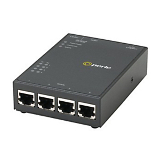
The IOLAN
•
External power supply*
•
A Quick Start Guide (this document)
•
Warranty Card
•
RJ45 - DB9 adapter (RJ45 models only excluding TS2
model)
•
A CD-ROM containing documentation and firmware
required to configure and operate the IOLAN
*Not included when purchasing Power over Ethernet models,
HL models and models with a screw terminal connector.
What You Need to Supply
•
Serial cable(s) to connect your serial devices to the IOLAN
•
An Ethernet 10/100BASE-T cable to connect the IOLAN
to the network
Hardware Setup
Connecting Serial Devices
Please refer to the pin-out table and ensure you have the
appropriate cable for connecting your serial device to one of
the RJ45 serial ports on the IOLAN.
NOTE: The STS8-D model uses the 8 pin connector (pins 2
through 9) and only supports EIA-232.
EIA-485
EIA-485
Pinout EIA-232
EIA-422
Full Duplex
Half Duplex
1
Power In
Power In
Power In
Power In
2 (in)
DCD
3 (out) RTS
TxD+
TxD
TxD+/RxD+
4 (in)
DSR
5 (out) TxD
TxD-
TxD-
TxD-/RxD-
6 (in)
RxD
RxD+
RxD+
7
GND
GND
GND
GND
8 (in)
CTS
RxD-
RxD-
9 (out) DTR
10
Power Out Power Out Power Out
Power Out
Power Out, Pin 10, is only available on STS4-D and SDS
models.
Connecting the LAN
•
Connect the IOLAN to the HUB or Switch that will
provide the network connectivity.
Setting the Dip Switch
•
The dip switch on the IOLAN is set in the factory to serial.
Unless you plan to attach a console to the IOLAN, leave
the dip switch in the serial position.
Connecting the Power
Models with a barrel connector
•
Plug the power adapter into a power socket and connect
the barrel connector end into the IOLAN. A solid green
LED indicates the unit is powered up.
Models with a terminal block
1. Ensure power is NOT applied to the wires prior to
connection.
2. On each end wire, remove the insulation from the copper
wire 5 mm (3/16 of an inch).
Note:
For I/O models the Terminal Block is pluggable.
3. Loosen the left screw on the top of the terminal connector
block, then insert your positive (+) wire into the left
terminal and screw it down tight. Loosen the right screw on
the top of the terminal connector block, then insert your
negative (-) wire into the right terminal and screw it down
tight.
-
+
Left
Right
4. Plug the power supply into the electrical outlet.
5. A solid green LED indicates the unit is powered up.
Input Voltage Range: (9-30v DC).
Typical Power Consumption @ 12v DC;
IOLAN SDS4 HL —2.4 Watts
IOLAN SDS3 M — 2.1 Watts
Powering On Cycle
When the power is connected to the IOLAN, the Power/Ready
LED will cycle through several sequences and will end in a
solid green once the unit is fully booted and ready to be
configured.
If the LED is not solid green after two minutes, refer to the
User's Guide for help identifying the reason.
LED Guide
Power/Ready—(Green/Yellow/Red)
•
Green—
•
Solid = System Ready
•
Flashing = System is booting or dip switch is in
console mode
•
Yellow—
•
Flashing = Booting
•
Red—Error condition (refer to the User's Guide for
details)
Link/10/100
•
Green—10 Mbits
•
Yellow—100 Mbits
•
Off—No LAN connection
Activity—Flashes for LAN RX/TX activity
Tx—Flashes with transmit serial activity
Rx—Flashes with receive serial activity
Configuring the Unit
The CD_ROM provided with your IOLAN includes software
for configuring the unit. This software is designed for use on a
Windows Operating System. For other Operating Systems,
please refer to the IOLAN User's Guide for methods of
configuring the IOLAN.
1. Insert the CD-ROM into the PC.
It should launch automatically. If it does not launch, open
Windows Explorer and point to the CD-ROM Drive.
Double click on the index file to launch the main page.
2. From the main page, select the Easy Config Wizard to
launch the configuration wizard or alternatively, install the
DeviceManager software and use it to configure the
IOLAN.
Default admin Password
You will be prompted by the software for the admin user
password before being allowed to configure the IOLAN.
The factory default password for the admin user is:
superuser (case sensitive)
You should change the admin password to restrict
unauthorized access to the IOLAN.
For additional methods of configuring your IOLAN (i.e.,
HTTP, Telnet, SNMP), please refer to the IOLAN User's
Guide.
Advertisement

Related Manuals for Perle IOLAN SDS4 HL


Summary of Contents for Perle IOLAN SDS4 HL
- Page 1 Input Voltage Range: (9-30v DC). • An Ethernet 10/100BASE-T cable to connect the IOLAN to the network Typical Power Consumption @ 12v DC; IOLAN SDS4 HL —2.4 Watts IOLAN SDS3 M — 2.1 Watts...
-
Page 2: Quick Start Guide
The SDS4 HL is suitable for use in Class I, Division 2 Desktop groups A,B,C,D or unclassified locations. Perle offers free technical support to Perle Authorised Distributors and Registered Perle Resellers. To access technical support, please visit the Perle WARNING - EXPLOSION HAZARD - DO NOT website at www.perle.com/support.
Need help?
Do you have a question about the IOLAN SDS4 HL and is the answer not in the manual?
Questions and answers