Perle IOLAN DS1 User Manual
Hide thumbs
Also See for IOLAN DS1:
- User manual (224 pages) ,
- Cli reference manual (93 pages) ,
- Manual (12 pages)
Table of Contents
Advertisement
Quick Links
Advertisement
Table of Contents

Related Manuals for Perle IOLAN DS1


Summary of Contents for Perle IOLAN DS1
- Page 1 IOLAN DS1/TS2 User’s Guide Version 4.3 Part #5500162-43 January 2012...
- Page 2 Markham, ON Canada L3R 0E1 Perle reserves the right to make changes without further notice, to any products to improve reliability, function, or design. Perle, the Perle logo, and IOLAN are trademarks of Perle Systems Limited. Microsoft, Windows 98, Windows NT, Windows 2000/Vista, Windows Server 2003, Windows XP, Server 2008 and Internet Explorer are trademarks of Microsoft Corporation.
-
Page 3: Table Of Contents
General Features ................22 Security ....................22 Chapter 2 Hardware and Connectivity ......24 Introduction ................24 IOLAN Components..............24 What’s Included ..................24 What You Need to Supply..............24 Available Accessories................24 Power Supply Specifications............ 25 IOLAN DS1/TS2 User’s Guide, Version 4.3... - Page 4 Table of Contents Desktop Models ..................25 Serial Only Models ................25 I/O Models ..................25 Getting to Know Your IOLAN ............25 Overview ....................25 DS1 ......................26 TS2 ......................26 I/O ......................27 Top View..................... 27 End View .................... 27 Console/Serial Switch ................
- Page 5 Table of Contents Features....................36 Connecting to the IOLAN Using WebManager ........36 Using WebManager ................38 Command Line Interface ............39 Overview....................39 Access Platforms ................... 39 Features....................39 Connecting to the IOLAN Using the CLI..........39 Through the Network................39 Through the Serial Port ..............
- Page 6 Table of Contents Setting Up the Network ..............47 Using DeviceManager................47 Using WebManager................. 48 Using a Direct Serial Connection to Specify an IP Address ....48 Using a Direct Serial Connection to Enable BOOTP/DHCP....49 Using ARP-Ping ..................50 For an IPv6 Network ................50 Setting Up the Serial Port(s)............51 Setting Up Users.................53 Chapter 5 Using DeviceManager and WebManager..54...
- Page 7 Table of Contents Functionality ................... 62 Editing a Serial Port ................63 Resetting a Serial Port ............... 64 Serial Port Profiles..............65 Common Tabs..................65 Overview .................... 65 Hardware Tab Field Descriptions............65 Packet Forwarding Tab Field Descriptions ........67 Console Management Profile ..............
- Page 8 Table of Contents General Tab Field Descriptions ............97 Advanced Tab Field Descriptions............98 Virtual Modem Profile ................99 Overview..................... 99 Functionality ..................99 General Tab Field Descriptions ............100 Advanced Tab Field Descriptions............. 101 Phone Number to Host Mapping ............103 VModem Phone Number Entry............
- Page 9 Table of Contents Overview ..................119 Field Descriptions................119 IPv6 Settings ..................120 Overview ..................120 Field Descriptions................120 Adding/Editing a Custom IPv6 Address..........121 Field Descriptions................121 Advanced ....................122 Overview ..................122 Field Descriptions................122 Advanced.................. 123 Host Table ..................... 123 Overview ..................
- Page 10 Table of Contents Overview................... 131 Field Descriptions ................131 Sessions Tab..................132 Overview................... 132 Functionality ..................132 Field Descriptions ................133 Serial Port Access Tab ................. 134 Overview................... 134 Field Descriptions ................134 Chapter 9 Configuring Security ........136 Introduction................136 Services..................136 Overview ....................136 Functionality..................
- Page 11 Table of Contents Analog ....................145 Overview ..................145 Field Descriptions................146 Digital Input................... 147 Overview ..................147 Functionality ..................147 Field Descriptions................148 Digital Output..................150 Overview ..................150 Functionality ..................150 Field Descriptions................151 Relay ...................... 153 Overview ..................153 Field Descriptions................
- Page 12 Table of Contents Serial Port Coil/Register Descriptions ..........171 A4/T4 Registers..................171 A4D2/A4R2 Registers ................172 D4/D2R2 Registers................173 Serial Pin Signals..................173 TruePort I/O................174 TruePort/Modbus Combination ............174 API Over TruePort Only................ 175 Accessing I/O Data Via TruePort..........176 Introduction ................... 176 Setup ......................
- Page 13 Table of Contents SNMP Traps Tab Field Descriptions..........184 Custom App/Plugin ................185 Overview ..................185 Field Description ................185 Advanced ....................186 Overview ..................186 Login Tab Field Descriptions............186 Bootup Files Tab Field Descriptions ..........187 Message of the Day (MOTD) Tab Field Descriptions ...... 188 TFTP Tab Field Descriptions ............
- Page 14 Table of Contents Setting the IOLAN’s Date and Time........200 Rebooting the IOLAN............... 200 Resetting the IOLAN to Factory Defaults ......200 Language Support ..............201 Loading a Supplied Language ............201 Translation Guidance................202 Software Upgrades and Language Files ..........202 Downloading Terminal Definitions.........
- Page 15 Table of Contents Introduction ................216 1-Port IOLAN ..................216 IOLAN DB25 Male/Female............... 216 IOLAN RJ45 ..................217 IOLAN DB9 ..................217 2-Port IOLAN ..................218 Digital I/O Module ................. 219 Analog Input Module ................220 Appendix D I/O Wiring Diagrams ........222 Wiring I/O Diagrams..............
- Page 16 Contacting Technical Support..........246 Making a Technical Support Query ............ 246 Who To Contact ................246 Have Your Product Information Ready ..........246 Making a support query via the Perle web page ......246 Repair Procedure.................. 247 Feedback on this Manual..............247...
- Page 17 Table of Contents Appendix H Data Logging ..........248 Introduction ................248 Trueport Profile ................ 248 TCP Socket Profile..............248 Appendix I Modbus Remapping........249 Configuring the Modbus UID Translation Feature ....249 Glossary ................251 Index .................253...
-
Page 18: Preface
IOLAN 2-4-Port Quick Start Guide IOLAN I/O Quick Start Guide IOLAN DS1/TS2 User’s Guide IOLAN DS1/TS2 Command Line Reference Guide TruePort User’s Guide TruePort Installation and Configuration Guide for Windows NT Online Help in the DeviceManager (automatically installed with the DeviceManager application) Link to knowledge base IOLAN DS1/TS2 User’s Guide, Version 4.3... -
Page 19: Typeface Conventions
Typeface Conventions Typeface Conventions Most text is presented in the typeface used in this paragraph. Other typefaces are used to help you identify certain types of information. The other typefaces are: Typeface Example Usage At the C: prompt, type: This typeface is used for code examples and system- generated output. -
Page 20: Chapter 1 Introduction
IOLAN feature set in addition to the general IOLAN functionality. Hardware on page 21 for information about the hardware specifications for your IOLAN model. Software on page 22 for a list of the basic and advanced software features. IOLAN DS1/TS2 User’s Guide, Version 4.3... -
Page 21: Iolan Features
Serial Power In Pin RJ45 DB25F DB25M Serial Power Out Pin RJ45 Auto Sensing 10/100 Ethernet Interface 10/100/1000 PCI Interface I/O Interface Power over Ethernet External AC Power Supply Internal AC Dedicated Console Port IOLAN DS1/TS2 User’s Guide, Version 4.3... -
Page 22: Software
Support for TCP/IP and UDP protocols including telnet and raw connections. Printer support via LPD and RCP. Virtual modem emulation. ‘Fixed tty’ support for several operating systems using Perle’s TruePort utility. DHCP/BOOTP for automated network-based setup. Dynamic statistics and line status information for fast problem diagnosis. - Page 23 IOLAN Features IOLAN DS1/TS2 User’s Guide, Version 4.3...
-
Page 24: Chapter 2 Hardware And Connectivity
RJ45 to DB25 DTE Male adapter RJ45 to DB25 DCE Male adapter RJ45 to DB25 DTE Female adapter RJ45 to DB9 Male DTE adapter RJ45 to DB9 Female DTE adapter Contact your distributor for details. IOLAN DS1/TS2 User’s Guide, Version 4.3... -
Page 25: Power Supply Specifications
2 is not used. Reset—The inset RESET button will reboot the IOLAN if pushed in and released quickly. It will reset the IOLAN to factory defaults if pushed in and held for more than three seconds. IOLAN DS1/TS2 User’s Guide, Version 4.3... -
Page 26: Ds1
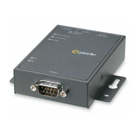
Activity (LAN) Serial Activity Serial Port The IOLAN DS1 has one serial connection that is one of the following connectors: DB25 male, DB25 female, RJ45, or DB9 male. This section describes the components found on the IOLAN TS2 model. Console/Serial... -
Page 27: I/O
The IOLAN I/O model shown is an A4D2. Different IOLAN I/O models have different I/O connector configurations. I/O connectors I/O connectors External Power Supply Reset Console/Serial Serial Port Ethernet Switch All IOLAN I/O models have a DB9M serial connector. IOLAN DS1/TS2 User’s Guide, Version 4.3... -
Page 28: Console/Serial Switch
Getting to Know Your IOLAN Console/Serial Switch Located at the back of the desktop IOLAN models is a switch that controls whether serial port 1 is in Console or Serial mode. Look at your model to verify the direction of the ON switch position. ON indicates that serial port 1 is in Console mode;... -
Page 29: Powering Up The Iolan
Before you start to configure the IOLAN, you should set the IOLAN jumpers for Digital I/O (see Digital I/O Module on page 219) or Analog Input (Analog Input Module on page 220) channels. IOLAN DS1/TS2 User’s Guide, Version 4.3... -
Page 30: Chapter 3 Configuration Methods
Once an IP address is assigned to the IOLAN, you can use any of the configuration methods to: Configure users. Configure IOLAN system parameters. Configure serial port parameters. Configure network parameters. Configure time parameters. Reboot the IOLAN. Manage I/O channels (when applicable). View statistics while connected to the IOLAN. IOLAN DS1/TS2 User’s Guide, Version 4.3... -
Page 31: Configuration Methods Overview
Requires a Configured IP Address The following configuration methods require that an IP address already be assigned to the IOLAN. WebManager—WebManager is a fully functional, browser-based configuration method. IOLAN DS1/TS2 User’s Guide, Version 4.3... -
Page 32: Easy Config Wizard
Printer (not supported on DS1/TS2 models) Serial Tunneling You can launch the Easy Config Wizard from the Perle website or from the installation CD-ROM. The Easy Config Wizard has been designed to walk you through the configuration process for any of the available configuration options shown on the Welcome window. -
Page 33: Devicemanager
Connecting to the IOLAN Using DeviceManager Before you can use DeviceManager, you need to install it on your Windows operating system from the IOLAN CD-ROM or you can download it from the Perle website. After the DeviceManager application is installed, click... - Page 34 DeviceManager All discovered IOLAN will be displayed on the list along with their name and IP address. When a new IOLAN is discovered on the network, that has not yet been assigned an IP address, it will be displayed with an IP Address of Not Configured. To configure the IP address, click on the IOLAN and then click the Assign IP button.
-
Page 35: Using Devicemanager
), the tree displays the same Serial options that appear as buttons in the display area, as shown below. This gives you the choice of using the navigation tree or buttons to navigate the options. IOLAN DS1/TS2 User’s Guide, Version 4.3... -
Page 36: Downloading The Configuration
WebManager Downloading the Configuration When you have completed all your configuration changes, click the button Download All Changes to download the configuration to the IOLAN. You must reboot the IOLAN for your configuration changes to take effect. WebManager Overview The WebManager is a web browser-based method of configuring/managing the IOLAN. It follows the same design as the DeviceManager, so it is easy to switch between the WebManager and DeviceManager when configuring your IOLAN. - Page 37 WebManager If you are accessing the IOLAN in non-secure HTTP, just type in the admin password (the factory default password is superuser IOLAN DS1/TS2 User’s Guide, Version 4.3...
-
Page 38: Using Webmanager
WebManager Using WebManager After you have successfully logged into WebManager, you will see the following: Navigation Tree System Information You navigate through the different configuration windows by selecting an option in the left-hand navigation tree. If click on option that is next to a folder, more navigation are displayed when you click on it: Navigation Tabs Network... -
Page 39: Command Line Interface
If the login is successful, you will get a prompt that displays the IOLAN model and number of ports: Login: admin Password: DS1# You will see a prompt that displays the model and number of the IOLAN. You are now ready to start configuring/managing your IOLAN using the CLI. IOLAN DS1/TS2 User’s Guide, Version 4.3... -
Page 40: Through The Serial Port
Menu Through the Serial Port To connect to the IOLAN through the serial port to configure/manage it using the CLI (or Menu), see Using a Direct Serial Connection to Specify an IP Address on page After you have established a connection to the IOLAN, you will get a Login: prompt. -
Page 41: Using The Menu
(lowercase L) to get a list of options, use the Space Bar up/down arrows to highlight the option you want, and then press to select it. Enter IOLAN DS1/TS2 User’s Guide, Version 4.3... -
Page 42: Dhcp/Bootp
DHCP/BOOTP DHCP/BOOTP Overview Several IOLAN parameters can be configured through a DHCP/BOOTP server during the IOLAN bootup. This is particularly useful for configuring multiple IOLANs. Not all configuration parameters are supported in the DHCP/BOOTP configuration (see DHCP/BOOTP Parameters on page 43 for supported configuration parameters), so you will need to use another configuration method, such as DeviceManager, WebManager or CLI, to complete the configuration. -
Page 43: Dhcp/Bootp Parameters
For example, 192.101.34.211 /accounting/Iolan_ds_german.txt. EXTRA_TERM1—(EXTRA_TERM2, EXTRA_TERM3) The full path, pre-fixed by a hostname/IP address (IPv4 or IPv6), and file name of a termcap file for a specific terminal type. IOLAN DS1/TS2 User’s Guide, Version 4.3... -
Page 44: Snmp
To connect to the IOLAN through an SNMP Management tool or MIB browser, do the following: Load the file from the IOLAN CD-ROM or Perle website into your SNMP perle-ds.MIB manager (this MIB works for all DS1 and TS2 models). -
Page 45: Using The Snmp Mib
If you want to save all the changes that have been submitted to the IOLAN, you need to expand the adminInfo container folder and adminFunction to write to FLASH. To make the configuration changes take effect, to reboot the IOLAN. adminFunction IOLAN DS1/TS2 User’s Guide, Version 4.3... -
Page 46: Chapter 4 Getting Started
The Easy Config Wizard quickly sets up the IOLAN’s network configuration and all serial ports to one of the following: Console Management—Allows users on the network to connect to a serial device that is connected to a serial port on the IOLAN. IOLAN DS1/TS2 User’s Guide, Version 4.3... -
Page 47: Setting Up The Network
Setting Up the Network TruePort (Virtual COM Port)—Allows a networked system to communicate with your serial device through a virtual COM or TTY port, using the Perle TruePort software. TCP Sockets (Raw TCP)—Allows hosts on the network to communicate with a serial device that requires raw data throughput (such as a printer or card reader) connected to the IOLAN serial port. -
Page 48: Using Webmanager
Setting Up the Network Expand the Server Configuration folder and select Server . Verify the IP address configuration. You should also enter a name in the field to make the IOLAN easily identifiable. Server Name To make your edits take effect, you need to download the new configuration file and then reboot the IOLAN. -
Page 49: Using A Direct Serial Connection To Enable Bootp/Dhcp
IOLAN on the console port and reboot it or push the Reset to Factory button to access the IOLAN. You are now ready to configure the IOLAN. See Chapter 3, Configuration Methods on page 30 information on the different IOLAN configuration methods. IOLAN DS1/TS2 User’s Guide, Version 4.3... -
Page 50: Using Arp-Ping
Setting Up the Network Using ARP-Ping You can use the ARP-Ping (Address Resolution Protocol) method to temporarily assign an IP address and connect to your IOLAN to assign a permanent IP address. To use ARP-Ping to temporarily assign an IP address: From a local UNIX/Linux host, type the following at the system command shell prompt: arp -s a.b.c.d aa:bb:cc:dd:ee:ff ®... -
Page 51: Setting Up The Serial Port(S)
When the serial device connected to the IOLAN initiates a modem connection, the IOLAN starts up a TCP connection to another IOLAN configured with a Virtual Modem serial port or to a host running a TCP application. IOLAN DS1/TS2 User’s Guide, Version 4.3... - Page 52 Setting Up the Serial Port(s) Control Signal I/O—The Control Signal I/O profile enables the use of the EIA-232 serial port signal pins to be used as assigned Digital Inputs or Digital Outputs. Modbus Gateway—The Modbus Gateway profile configures a serial port to act as a Modbus Master Gateway or a Modbus Slave Gateway.
-
Page 53: Setting Up Users
To quickly add a user, fill out the field in the General tab and click Chapter 8, Configuring Users on page 126 for more information about the other user parameters you can configure. IOLAN DS1/TS2 User’s Guide, Version 4.3... -
Page 54: Chapter 5 Using Devicemanager And Webmanager
In DeviceManager, you must download your configuration changes to the IOLAN either periodically or after you are done with the configuration changes. From both managers you must reboot the IOLAN in order for you configuration changes to take effect. IOLAN DS1/TS2 User’s Guide, Version 4.3... -
Page 55: Navigating Devicemanager/Webmanager
See Using DeviceManager on page 35 for more information on how to navigate the pages of DeviceManager. Menu/Quick Access Buttons Navigation Tree Display Area IOLAN DS1/TS2 User’s Guide, Version 4.3... -
Page 56: Webmanager
Navigating DeviceManager/WebManager WebManager The WebManager uses an expandable/collapsible buttons with folders and pages for the navigation tree. You can expand the buttons to view the folders and pages to see the available configuration options. When you access a configuration page, you can often navigate the tabs in the configuration area to access all of the configuration options. -
Page 57: Using Devicemanager To Connect To The Iolan
IOLAN’s IP address; this field supports IPv4 and IPv6 addresses. Click the button when you have completed adding all the manual entries. Select Close the manually added server to connect to it. IOLAN DS1/TS2 User’s Guide, Version 4.3... -
Page 58: Assigning A Temporary Ip Address To A New Iolan
Using DeviceManager to Connect to the IOLAN Assigning a Temporary IP Address to a New IOLAN You can temporarily assign an IP address to the IOLAN that is connected to your local network segment, for the purpose of connecting to it and downloading a configuration file (containing a permanent IP address). -
Page 59: Adding/Deleting Iolans Manually
DeviceManager can communicate with the IOLAN’s IP Address. If the ping times out, then you might need to set up a Gateway in your IOLAN or verify that your network is communicating correctly. IOLAN DS1/TS2 User’s Guide, Version 4.3... -
Page 60: Using Webmanager To Connect To The Iolan
Using WebManager to Connect to the IOLAN Using WebManager to Connect to the IOLAN WebManager can only connect to IOLANs that already have an assigned IP address. To connect to the IOLAN, type the IP address of the IOLAN into the field as such: Address http://10.10.234.34... -
Page 61: Opening An Existing Configuration File
Most of the management tasks, such as setting the time/date, downloading keys/certificates, downloading firmware, downloading custom files, resetting serial ports, etc., are found under the menu option in the DeviceManager and under in WebManager. Tools Administration IOLAN DS1/TS2 User’s Guide, Version 4.3... -
Page 62: Chapter 6 Configuring Serial Ports
Serial Ports on your IOLAN. As you configure the serial ports, the information for each serial port is displayed. To configure/change a serial port, click the Edit button. IOLAN DS1/TS2 User’s Guide, Version 4.3... -
Page 63: Editing A Serial Port
Serial Ports Editing a Serial Port In the Serial Port Settings window, click on a serial port and then click the button, the Edit following window is displayed: IOLAN DS1/TS2 User’s Guide, Version 4.3... -
Page 64: Resetting A Serial Port
Serial Ports Click the Change Profile button to select a different serial port profile if you don’t want the displayed profile: As you select the different serial port profiles, a short description and a picture representing a typical application of the profile is displayed. When you have selected the appropriate profile for the serial port, click and those serial port profile configuration options will be displayed. -
Page 65: Serial Port Profiles
The exact baud rate calculated can be viewed in the Serial Ports statistics. Range: 50-230400, custom supports 50-1843200 Default: 9600 Data Bits Specifies the number of bits in a transmitted character. Default: 8 IOLAN DS1/TS2 User’s Guide, Version 4.3... - Page 66 Serial Port Profiles Parity Specifies the type of parity being used for the data communication on the serial port. If you want to force a parity type, you can specify for 1or Mark Space Data Options: Even, Odd, Mark, Space, None Default: None Stop Bits Specifies the number of stop bits that follow a byte.
-
Page 67: Packet Forwarding Tab Field Descriptions
IOLAN. Range: 0-65535 Default: 250 ms Custom Packet This option allows you to define the packet forwarding rules based on the Forwarding packet definition or the frame definition. Default: Disabled IOLAN DS1/TS2 User’s Guide, Version 4.3... - Page 68 Serial Port Profiles Packet Definition When enabled, this group of parameters allows you to set a variety of packet definition options. The first criteria that is met causes the packet to be transmitted. For example, if you set a ms and a Force Transmit Timer 1000 bytes, whichever criteria is met first is what will cause the...
-
Page 69: Console Management Profile
TCP socket that will listen for a Telnet connection from the network. Functionality Use the Console Management profile when you are configuring users who need to access a serial console port from the network. IOLAN DS1/TS2 User’s Guide, Version 4.3... -
Page 70: General Tab Field Descriptions
Serial Port Profiles General Tab Field Descriptions tab configures how the serial port will be accessed by the user Console Management General through the network. Configure the following parameters: Protocol Specify the connection method that users will use to communicate with a serial device connected to the IOLAN through the network. -
Page 71: Advanced Tab Field Descriptions
Use this timer to close a connection because of inactivity. When the Idle expires, the IOLAN will end the connection. Timeout Default: seconds so the port will never timeout Range: 0-4294967 seconds (about 49 days) IOLAN DS1/TS2 User’s Guide, Version 4.3... - Page 72 Serial Port Profiles Session Timeout Use this timer to forcibly close the session/connection when the Session expires. Timeout Default: seconds so the port will never timeout Range: 0-4294967 seconds (about 49 days) Break Handling Specifies how a break is interpreted. Data Range: None—The IOLAN ignores the break key completely and it is not passed through to the host.
-
Page 73: Trueport Profile
See the TruePort User’s Guide for more details about the TruePort client software. General Tab Field Descriptions tab determines how the TruePort connection is initiated and then sets up the TruePort General appropriate connection parameters. IOLAN DS1/TS2 User’s Guide, Version 4.3... - Page 74 Serial Port Profiles Configure the following parameters: Connect to remote When enabled, the IOLAN initiates communication to the TruePort client. system Default: Enabled Host Name The configured host that the IOLAN will connect to (must be running TruePort). Default: None TCP Port The TCP Port that the IOLAN will use to communicate through to the TruePort client.
-
Page 75: Adding/Editing Additional Trueport Hosts
Once connected to the backup, the IOLAN will attempt to re-establish a connection to the Primary host, once this is successfully done, it gracefully shuts down the backup connection. Default: Disabled IOLAN DS1/TS2 User’s Guide, Version 4.3... -
Page 76: Adding/Editing A Multihost Entry
Serial Port Profiles Primary Host Specify a preconfigured host that the serial device will communicate to through the IOLAN. Default: None TCP Port Specify the TCP port that the IOLAN will use to communicate to the Primary Host Default: 0 Backup Host Specify a preconfigured host that the serial device will communicate to through the IOLAN if the IOLAN cannot communicate with the... -
Page 77: Advanced Tab Field Descriptions
"testing" the connection. It should be noted that if a network connection is accidentally dropped, it can take as long as the specified interval before anyone can reconnect to the serial port. Default: Disabled IOLAN DS1/TS2 User’s Guide, Version 4.3... - Page 78 Serial Port Profiles Enable Data When enabled, serial data will be buffered if the TCP connection is lost. When Logging the TCP connection is re-established, the buffered serial data will be sent to its destination. Only valid in Trueport LITE mode. Not valid when using [Trueport Lite Trueport in Full Mode.
- Page 79 The number of times the IOLAN will attempt to re-establish a connection with a remote modem. Range: 0-99 Default: 2 Modem The name of the predefined modem that is used on this line. Phone The phone number to use when is enabled. Dial Out IOLAN DS1/TS2 User’s Guide, Version 4.3...
-
Page 80: Tcp Sockets Profile
Serial Port Profiles TCP Sockets Profile Overview The TCP Socket profile allows for a serial device to communicate over a TCP network. The TCP connection can be initiated from a host on the network and/or a serial device. This is typically used with an application on a Workstation or Server that communicates to a device using a specific TCP socket. - Page 81 Default: Disabled Permit When this option is enabled, you can select both checkbox options "listen for Connections in connection" and "connect to". Both Directions Default: Disabled IOLAN DS1/TS2 User’s Guide, Version 4.3...
-
Page 82: Adding/Editing Additional Hosts
Serial Port Profiles Adding/Editing Additional Hosts You can define a list of hosts that the serial device will communicate to or a primary/backup host. Configure the following parameters: Define additional When this option is enabled, you can define up to 49 hosts that the serial device hosts to connect to connected to this serial port will attempt communicate to. -
Page 83: Adding/Editing A Multihost Entry
Configure the following parameters: Host Name Specify the preconfigured host that will be in the multihost list. Default: None TCP Port Specify the TCP port that the IOLAN will use to communicate to the Host Default: 0 IOLAN DS1/TS2 User’s Guide, Version 4.3... -
Page 84: Advanced Tab Field Descriptions
Serial Port Profiles Advanced Tab Field Descriptions Configure the following parameters: Authenticate User Enables/disables login/password authentication for users connecting from the network. Default: Disabled Enable TCP Enables a per-connection TCP keepalive feature. After the configured number Keepalive of seconds, the connection will send a gratuitous ACK to the network peer, thus either ensuring the connection stays active OR causing a dropped connection condition to be recognized. - Page 85 The number of times the IOLAN will attempt to re-establish a connection with a remote modem. Range: 0-99 Default: 2 Modem The name of the predefined modem that is used on this line. Phone The phone number to use when Dial Out is enabled. IOLAN DS1/TS2 User’s Guide, Version 4.3...
-
Page 86: Udp Sockets Profile
Serial Port Profiles UDP Sockets Profile Overview The UDP profile configures a serial port to send or receive data to/from the LAN using the UDP protocol. Functionality You can use UDP profile in the following two basic modes. The first is to send data coming from the serial device to one or more UDP listeners on the LAN. - Page 87 LAN will be sent to this UDP port. Until the port is learned, data from the serial port intended to be sent to the LAN will be discarded. IOLAN DS1/TS2 User’s Guide, Version 4.3...
- Page 88 Serial Port Profiles Port - Serial data being forwarded to the LAN from the serial device will sent to this UDP port. Only data originating from the UDP port configured here (as well as originating from a host in the IP range defined for this entry) will be forwarded to the serial device. Special values for "Start IP address"...
-
Page 89: General Tab Field Descriptions
Port—The port that the IOLAN will use to relay messages to servers/hosts. This option works with any except . The Direction Disabled IOLAN will listen for UDP packets on the port configured by the Listen parameter. for connections on UDP port Default: Auto Learn IOLAN DS1/TS2 User’s Guide, Version 4.3... -
Page 90: Advanced Tab Field Descriptions
Serial Port Profiles Port The UDP port to use. Default: 0 (zero) Advanced Tab Field Descriptions Configure the following parameters: Controls the sending of ASCII strings to serial devices at session start as Session Strings follows; Send at Start—If configured, this string will be sent to the serial device on power-up of the IOLAN or when a kill line command is issued on the serial port. -
Page 91: General Tab Field Descriptions
User Service parameter for locally configured users parameter for users who are externally Default User Service authenticated User Service Settings on page 94 for field descriptions of the various User Service Settings. IOLAN DS1/TS2 User’s Guide, Version 4.3... -
Page 92: Advanced Tab Field Descriptions
Serial Port Profiles Connect to Remote When the serial port is started, the IOLAN will initiate a connection to the System specified host using the specified protocol. With this option, user authentication will not be performed by the IOLAN. Default: Disabled Protocol Specify the protocol that will be used to connect to the specified host. - Page 93 Default: 10 ms Dial Timeout The number of seconds the IOLAN will wait to establish a connection to a remote modem. Range: 1-99 Default: 45 seconds IOLAN DS1/TS2 User’s Guide, Version 4.3...
-
Page 94: User Service Settings
Serial Port Profiles Dial Retry The number of times the IOLAN will attempt to re-establish a connection with a remote modem. Range: 0-99 Default: 2 Dial In If the device is remote and will be dialing in via modem or ISDN TA, enable this parameter. -
Page 95: Telnet Settings
Echo Defines the echo character. When , typing the echo character Line Mode echoes the text locally and sends only completed lines to the host. This value is in hexadecimal. Default: 5 (ASCII value IOLAN DS1/TS2 User’s Guide, Version 4.3... -
Page 96: Serial Tunneling Profile
Serial Port Profiles Escape Defines the escape character. Returns you to the command line mode. This value is in hexadecimal. Default: 1d (ASCII value Serial Tunneling Profile Overview The Serial Tunneling profile allows two IOLANs to be connected back-to-back over the network to establish a virtual link between two serial ports based on RFC 2217. -
Page 97: General Tab Field Descriptions
A preconfigured host name that is associated with the IP address of the Tunnel Server. TCP Port The TCP port that the IOLAN will use to connect to the Tunnel Server. Default: 10000+serial port number; so serial port 5 is 10005. IOLAN DS1/TS2 User’s Guide, Version 4.3... -
Page 98: Advanced Tab Field Descriptions
Serial Port Profiles Advanced Tab Field Descriptions Configure the following parameters: Break Length When the IOLAN receives a command from its peer to issue a break signal, this paramters defines the length of time the break condition will be asserted on the serial port Default: 1000ms (1 second) Delay After Break... -
Page 99: Virtual Modem Profile
For example, or you can use ATD123.34.23.43,10001 , without any punctuation (although you do need to add zeros where there ATD12303402304310001 are not three digits presents, so that the IP address is 12 digits long). IOLAN DS1/TS2 User’s Guide, Version 4.3... -
Page 100: General Tab Field Descriptions
Serial Port Profiles General Tab Field Descriptions Configure the following parameters: Listen on TCP Port The IOLAN TCP port that the IOLAN will listen on. Default: 10000 + serial port number (for example, serial port 12 defaults to 10012) Connect When enabled, automatically establishes the virtual modem connection when Automatically At the serial port becomes active. -
Page 101: Advanced Tab Field Descriptions
Specify this option to make the DTR signal always act as a RI signal. Default: Disabled RTS Signal Always Specify this option to make the RTS signal always act as a RTS signal. Default: Enabled IOLAN DS1/TS2 User’s Guide, Version 4.3... - Page 102 Serial Port Profiles RTS Signal Acts as Specify this option to make the RTS signal always act as a DCD signal. Default: Disabled RTS Signal Acts as Specify this option to make the RTS signal always act as a RI signal. Default: Disabled DCD Signal Always When you configure the DTR or RTS signal pin to act as a DCD signal, enable...
-
Page 103: Phone Number To Host Mapping
Click on a phone number entry and click the Delete button to remove it from the phone number list. VModem Phone Number Entry Create an entry in the Phone Number to Host Mapping window. Configure the following parameters: IOLAN DS1/TS2 User’s Guide, Version 4.3... -
Page 104: Control Signal I/O Profile
Serial Port Profiles Phone Number Specify the phone number your modem application sends to the modem. Note: The IOLAN does not validate the phone number, so it must be entered in the exact way the application will send it. For example, if you enter 555-1212 in this table and the application sends 5551212, the IOLAN will not match the two numbers. -
Page 105: Input Signal Field Descriptions
When enabled, automatically clears the alarm when the trigger condition changes; for example, if the and the alarm is triggered, once Trigger Inactive the input becomes active again, the alarm will automatically be cleared Default: Enabled IOLAN DS1/TS2 User’s Guide, Version 4.3... -
Page 106: Output Signal Field Descriptions
Serial Port Profiles Manual Clear When enabled, a triggered alarm must be manually cleared. Mode Default: Disabled Syslog When enabled, sends a message to syslog when an alarm is triggered or cleared. The syslog entry includes the severity level and the value that caused the alarm to trigger or clear. -
Page 107: Modbus Gateway Profile
Access on page 169 for more information on using the Modbus protocol to access I/O data. Functionality The Modbus Gateway profile configures a serial port to act as a Modbus Master Gateway or a Modbus Slave Gateway. IOLAN DS1/TS2 User’s Guide, Version 4.3... -
Page 108: General Tab Field Descriptions
Serial Port Profiles General Tab Field Descriptions Configure the following parameters: Mode Specify how the Modbus Gateway is defined on the serial port. Data Options: Modbus Master—Typically, the Modbus Master is connected to the Serial Port and is communicating to Modbus Slaves on the network. Modbus Slave—Typically, the Modbus Master is accessing the IOLAN through the network to communicated to Modbus Slaves connected to the IOLAN’s Serial Ports. -
Page 109: Advanced Field Descriptions
Delay after Send—If configured, will inset a delay after the string is sent to the device. This delay can be used to provide the serial device with time to process the string before the session is initiated or terminated. Default: 10 ms IOLAN DS1/TS2 User’s Guide, Version 4.3... -
Page 110: Modbus Slave Ip Settings Field Descriptions
Serial Port Profiles Modbus Slave IP Settings Field Descriptions This window is used to configure the Modbus Slaves. The following buttons are available: Add Button Adds an entry into the Modbus Destination Slave IP Settings table. Edit Button Edits an entry in the Modbus Destination Slave IP Settings table. Delete Button Deletes an entry from the Modbus Destination Slave IP Settings table. - Page 111 Specify the protocol that is used between the Modbus Master and Modbus Slave(s). Data Options: TCP or UDP Default: TCP UDP/TCP Port The destination port of the remote Modbus TCP Slave that the IOLAN will connect to. Range: 0-65535 Default: 502 IOLAN DS1/TS2 User’s Guide, Version 4.3...
-
Page 112: Modbus Slave Advanced Settings Field Descriptions
Serial Port Profiles Modbus Slave Advanced Settings Field Descriptions Configure the following parameters: TCP/UDP Port The network port number that the Slave Gateway will listen on for both TCP and UDP messages. Default: 502 Next Request Delay A delay, in milliseconds, to allow serial slave(s) to re-enable receivers before issuing next Modbus Master request. -
Page 113: Custom Application Profile
Custom App/Plugin profile is used in conjunction with custom applications created for the IOLAN by using the Perle SDK. See the SDK Programmer’s Guide (the SDK and guide are accessible via a request form located on the Perle website at ) for information about the functions that www.perle.com/supportfiles/SDK_Request.shtml... -
Page 114: Advanced
Advanced Advanced Advanced Serial Settings Tab Overview Advanced serial port settings apply to all serial ports. Field Descriptions Configure the following parameters: Process Break Enables/disables the Telnet break signal and the out-of-band break signals for Signals TruePort. Default: Disabled Flush Data Before When enabled, deletes any pending data when a port is closed. -
Page 115: Modems Tab
When you click on the tab, you will see the following: Modems If any modems have been configured, they will be displayed. Adding/Editing a Modem You can add new modems or edit existing modems through the following window: IOLAN DS1/TS2 User’s Guide, Version 4.3... - Page 116 Advanced Configure the following parameters: Name The name of the modem. Restrictions: Do not use spaces. Initialization String The initialization string of the modem; see your modem’s documentation.
-
Page 117: Trueport Baud Rate Tab
Field Definitions Configure the following parameter: Actual Baud Rate The actual baud rate that runs between the IOLAN and the connected serial device. Range: 50-230400, you can also specify a custom baud rate IOLAN DS1/TS2 User’s Guide, Version 4.3... -
Page 118: Chapter 7 Network Settings
IPv6 address, and Ethernet information. See IP Settings on page 119 for more information. Advanced—This window configures hosts that the IOLAN will be communicating with and routes. See Advanced on page 123 for more information on these options. IOLAN DS1/TS2 User’s Guide, Version 4.3... -
Page 119: Ip Settings
IP Settings IP Settings IPv4 Settings Overview The parameters in IPv4 settings are used to access the IOLAN and are how the IOLAN accesses the network. Field Descriptions Configure the following parameters: System Name System Name is used for informational purposes by such tools as the DeviceManager and is also used in conjunction with the Domain field to construct a fully qualified domain name (FQDN). -
Page 120: Ipv6 Settings
IP Settings Subnet Mask The network subnet mask. For example, 255.255.0.0. Default Gateway Specify the gateway IP address that will provide general access beyond the local network. Field Options: IPv4 address Default Gateway When DHCP/BOOTP is enabled, you can enable this option to have the Obtain IOLAN receive the Default Gateway IP address from the DHCP/BOOTP Automatically... -
Page 121: Adding/Editing A Custom Ipv6 Address
IP Settings Custom IPv6 List Displays the list of custom configured IPv6 addresses. Add Button Adds a custom IPv6 address. Edit Button Edits an existing IPv6 address. Delete Button Deletes an IPv6 address from the Custom IPv6 address list. Default Gateway Specify the gateway IP address that will provide general access beyond the local network. -
Page 122: Advanced
IP Settings Use the following Enable this option when you want to enter a specific IPv6 address. IPv6 address Default: Disabled IPv6 Address Specify the complete IPv6 address. Field Format: IPv6 address IPv6 Address IPv6 Specify the network prefix bits for the IPv6 address. Prefix Bits Range: 0-128 Default: 64... -
Page 123: Advanced
Advanced Advanced Host Table Overview The Host table contains the list of hosts that will be accessed by an IP address from the IOLAN. This table will contain a symbolic name for the host as well as its IP address. When a host entry is required elsewhere in the configuration, the symbolic name will be used. -
Page 124: Route List
Advanced Host Name The name of the host. This is used only for the IOLAN configuration. Text Characteristics: Up to 14 characters, no spaces. IP Address The host’s IP address. Text Characteristics: IPv4 or IPv6 Address Route List Overview Entering routes in the routing list enables the identification of gateways to be used for accessing specific hosts or external networks from the IOLAN's local network. - Page 125 Advanced Configure the appropriate parameters: Type Specify the type of route you want to configure. Data Options: Host—A route defined for accessing a specific host external to your local network. Network—A route defined for accessing a specific network external to your local network.
-
Page 126: Chapter 8 Configuring Users
When users are connecting to the IOLAN from a network connection, the user database can be used Authenticate users prior to providing access to a serially attached console port (such as a Unix server or router). IOLAN DS1/TS2 User’s Guide, Version 4.3... -
Page 127: User Settings
The Users window displays the users who have been configured. You can add users, edit existing users, or delete users from this window. See Adding/Editing Users on page 128 for information on the parameters available when adding or editing a user. IOLAN DS1/TS2 User’s Guide, Version 4.3... -
Page 128: Adding/Editing Users
Adding/Editing Users Adding/Editing Users General Tab Overview The General tab configures the basic user information. Functionality You must, minimally, provide a User Name Level for a user. Field Descriptions Configure the following parameters: User Name The name of the user. Restrictions: Do not use spaces. - Page 129 Host IP address 127.0.0.0 (local loop back). When the user connects to that serial port a Telnet session will be established to the IOLAN and the user will appear to have connected from the network. IOLAN DS1/TS2 User’s Guide, Version 4.3...
-
Page 130: Services Tab
Adding/Editing Users Services Tab Overview tab configures the connection parameters for a user. Any connection parameters Services configured in this window will override the serial port connection parameters. Functionality When a Terminal profile is set for the serial port and Require Login has been selected, user’s accessing the IOLAN through the serial port will be authenticated. -
Page 131: Advanced Tab
Menu or CLI. The IOLAN supports one custom language that must be downloaded to the IOLAN. Default: English Language Support on page 201 for more information about Custom Languages. IOLAN DS1/TS2 User’s Guide, Version 4.3... -
Page 132: Sessions Tab
Adding/Editing Users Hotkey Prefix The prefix that a user types to control the current session. Data Options: ^a number —To switch from one session to another, press (Ctrl-a) and then the required session number. For example, ^a 2 would switch you to session 2. -
Page 133: Field Descriptions
The host that the user will connect to in this predefined session. Default: None TCP Port The TCP port that the IOLAN will use to connect to the host in this predefined session. Default: 23 IOLAN DS1/TS2 User’s Guide, Version 4.3... -
Page 134: Serial Port Access Tab
Adding/Editing Users Serial Port Access Tab Overview tab controls the user’s read/write access on any given IOLAN serial port. Serial Port Access This pertains to users that are connecting from the network to a serial device over a Console Management type session. This can be useful when you have multiple users connecting to the same serial device and you wish to control the viewing and/or the write to and from the device. - Page 135 Adding/Editing Users IOLAN DS1/TS2 User’s Guide, Version 4.3...
-
Page 136: Chapter 9 Configuring Security
IOLAN. If you do not want to allow users to Telnet to the IOLAN, you can disable the Telnet Server service; therefore, disabling daemons can also be used as an added security method for accessing the IOLAN. By default, all daemon and client applications are enabled and running on the IOLAN. IOLAN DS1/TS2 User’s Guide, Version 4.3... -
Page 137: Field Descriptions
The DeviceManager listens on port 33812 and sends on port 33813. WebManager WebManager daemon process in the IOLAN listening on port 80. (HTTP) Note: TCP ports 2601, 2602 and 2603 are used internally by the IOLAN. IOLAN DS1/TS2 User’s Guide, Version 4.3... -
Page 138: Chapter 10 Configuring I/O Interfaces
Contact rating: 1A@30VDC, 0.5A@AC: 120VAC Breakdown voltage: 500 VAC (50/60 Hz) Relay on time: 7 msec. Relay off time 3 msec Total switching time: 10 msec Insulation resistance: 1000 MW minimum at 500 VDC IOLAN DS1/TS2 User’s Guide, Version 4.3... -
Page 139: Settings
TruePort COM redirector feature. TruePort Default: Disabled Modbus I/O Access on page 169 for function codes and I/O coil/registration descriptions and Accessing I/O Data Via TruePort on page for the Perle API. IOLAN DS1/TS2 User’s Guide, Version 4.3... -
Page 140: Advanced Slave Modbus Settings
Allow I/O Access Allows serial application access to the I/O over the network using the TruePort via API through COM redirector feature via a custom application using the Perle API. TruePort Default: Permanently enabled when Enable I/O Access via TruePort... -
Page 141: Failsafe Timer Functionality
Failsafe Timer provides a per channel or per serial signal output pin trigger mechanism that is activated when there are no TCP sessions for the specified amount of time. Field Descriptions Configure the following parameters: IOLAN DS1/TS2 User’s Guide, Version 4.3... - Page 142 Settings Enable I/O Failsafe Enables/disables the Failsafe Timer. This is the global setting that must be Timer enabled to set the Failsafe Action on the channel for digital output and relay channels or output signal pins. When this timer expires because of no I/O activity within the specified time interval, the Failsafe Action set for the channel determines the action on the output.
-
Page 143: Udp Functionality
Default: 30 seconds Settings Button Click this button to configure the UDP IP addresses that will receive the I/O status information. I/O UDP Settings on page 144 for field descriptions for the I/O UDP Settings window. IOLAN DS1/TS2 User’s Guide, Version 4.3... -
Page 144: I/O Udp Settings
Settings I/O UDP Settings Configure the following parameters: UDP Entry When enabled, broadcasts I/O status (data) to the specified range of IP addresses. Default: Disabled Start IP Address The first host IP address in the range of IP addresses (for IPV4 or IPV6) that the IOLAN will listen for messages from and/or send messages to. -
Page 145: Channels
(monitored by an Analog channel) a syslog message is sent to the Monitoring Application. The Monitoring Application then sends a command to the IOLAN via the Perle API that causes the Relay channel to activate an internal freezer dehumidifier. The relay is turned off when the Analog channel sends a clear syslog message to the Monitoring Application and the Relay channel is deactivated. -
Page 146: Field Descriptions
Channels Field Descriptions Configure the following parameters: Description Provide a description of the channel, making it easier to identify. Data Options: Maximum 20 characters, including spaces Type Select the type of input being measured. Data Options: Current or Voltage Default: Current Range Select the range for the measurement type. -
Page 147: Digital Input
Input Network Digital I/O IOLAN Monitoring Input Application Industrial Freezers IOLAN DS1/TS2 User’s Guide, Version 4.3... -
Page 148: Field Descriptions
Channels Field Descriptions Configure the following parameters: Description Provide a description of the channel, making it easier to identify. Data Options: Maximum 20 characters, including spaces Input Mode When selected, the channel will be reading the status of the line (input). The internal jumpers must match the software configuration;... - Page 149 Critical Default: Disabled SNMP When enabled, sends an SNMP trap when an alarm is triggered or cleared. The trap consists of the severity level and whether the alarm was triggered or cleared. Default: Disabled IOLAN DS1/TS2 User’s Guide, Version 4.3...
-
Page 150: Digital Output
In an industrial freezer warehouse, the IOLAN D4 is used to monitor the freezer doors. When one of the industrial freezer doors are left open for more than five minutes, the Monitoring Application (using the Perle API) starts the Digital output sink, causing the strobe light on top of the offending freezer to activate. -
Page 151: Field Descriptions
Inactive-to-Active Delay—The channel output will remain inactive for the specified time interval after it is manually started. Active-to-Inactive Delay—The channel output will go inactive after the specified time interval after it is manually started. Default: Manual IOLAN DS1/TS2 User’s Guide, Version 4.3... - Page 152 Channels Pulse Mode When is set to , you can specify the manner of the pulse. Output Pulse Data Options: Continuous—Continuously pulses active and inactive. Count—Pulses an active/inactive sequence for the specified number of times. Default: Continuous Pulse Count The channel output will pulse for the specified number of times; each count consists of an active/inactive sequence.
-
Page 153: Relay
The Relay channel is deactivated when the Analog channel sends a clear syslog message to the Monitoring Application and the Relay channel is deactivated. A4D2 Relay Network Analog Relay I/O Relay IOLAN Monitoring Application Industrial Freezers Analog IOLAN DS1/TS2 User’s Guide, Version 4.3... -
Page 154: Field Descriptions
Channels Field Descriptions Configure the following parameters: Description Provide a description of the channel, making it easier to identify. Data Options: Maximum 20 characters, including spaces Output Specify how the channel output will be handled. Data Options: Manual—You must manually manipulate the channel output. Pulse—Activates and deactivates the channel output activity in intervals after it is manually activated. -
Page 155: Digital I/O Extension
For example, when the door opens (I/O digital input sensor) in a factory, a light goes on in the reception office (remote IOLAN relay channel), and the door open/close is logged by an application on a remote host. Warehouse IOLAN Reception IOLAN Network Remote Host IOLAN DS1/TS2 User’s Guide, Version 4.3... -
Page 156: Functionality
Channels Functionality The Digital I/O extension feature requires the digital input to be connected to one or more digital outputs/relays (local or on another IOLAN model), output serial signal pins, and/or TCP/IP applications. In order to create a successful connection between the input and output or application, one side must be must be set to and the other side must be set to Listen for connection... -
Page 157: Field Descriptions
Default: 2000 for channel 1, then increments by one for each channel Allow Multiple When this option is enabled, multiple I/O channels and/or TCP/IP applications Hosts to Connect can connect to this channel/serial signal pin. Default: Disabled IOLAN DS1/TS2 User’s Guide, Version 4.3... - Page 158 Channels Connect to When enabled, the channel/serial signal pin initiates communication to another I/O channel or a TCP/IP application. Default: Enabled Host Name The configured host or another IOLAN that the I/O channel will connect to. Default: None TCP Port The TCP Port that the channel/serial signal pin will use to communicate to another IOLAN or a TCP/IP application.
-
Page 159: Adding/Editing Additional Hosts
Primary host, once this is successfully done, it gracefully shuts down the backup connection. Default: Disabled Primary Host Specify a preconfigured host that the I/O channel or serial signal pin will communicate to. Default: None IOLAN DS1/TS2 User’s Guide, Version 4.3... -
Page 160: Adding/Editing A Multihost Entry
Channels TCP Port Specify the TCP port that the I/O channel or serial signal pin will use to communicate to the Primary Host Default: 2000 for channel 1, then increments by one for each channel Backup Host Specify a preconfigured host that the I/O channel or serial signal pin will communicate to if the I/O channel cannot communicate with the Primary Host Default: None... -
Page 161: Temperature
In the following example, a Temperature I/O IOLAN is used to monitor industrial freezer temperature sensors, with an alarm set to send a syslog message if the temperature rises above 31 Network Temperature I/O IOLAN Monitoring Application Industrial Freezers IOLAN DS1/TS2 User’s Guide, Version 4.3... -
Page 162: Field Descriptions
Channels Field Descriptions Configure the following parameters: Description Provide a description of the channel, making it easier to identify. Data Options: Maximum 20 characters, including spaces Type Specify the type of sensor you are using to measure temperature. Data Options: RTD, Thermocouple Default: RTD Range Specify the temperature range that you want to measure. -
Page 163: Alarm Settings
Default: Disabled Send SNMP Alert When enabled, sends an SNMP trap when an alarm is triggered or cleared. The trap consists of the severity level and whether the alarm was triggered or cleared. Default: Disabled IOLAN DS1/TS2 User’s Guide, Version 4.3... -
Page 164: Advanced Analog Alarm Settings
Channels Advanced Analog Alarm Settings The advanced Analog Alarm Settings window expands the basic alarm settings options to up to five severity levels. Configure the following parameters: Trigger Type If the , an alarm is triggered when the input drops below Trigger Type the specified Trigger... -
Page 165: I/O Udp
Serial Pin Signal Section—The Serial Pin Signal Section of the UDP packet, which contains the status of the IOLAN’s serial port’s control signal pins. The Serial Pin Signal Data subsection within the Serial Signal Pins Section will always be present. IOLAN DS1/TS2 User’s Guide, Version 4.3... -
Page 166: Analog Section
I/O UDP Analog Section The Analog Section of the UDP packet is comprised of I/O data for each enabled Analog channel. Note: If the IOLAN I/O model does not support Analog channels, the Analog Channel Data subsection of the Analog Section will NOT be present in the UDP packet. Section Channel Analog Channel Data (for each enabled channel) -
Page 167: Digital/Relay Section
Pin Enabled (1 Byte, one bit for each serial pin signal) Serial Pin Signal Data—1 byte with each bit being set to high (1) or low (0) for the appropriate serial pin signals. IOLAN DS1/TS2 User’s Guide, Version 4.3... -
Page 168: Udp Unicast Example
I/O Modbus Slave UDP Unicast Example For an example of the I/O UDP unicast, see the sample program, , found on your CD- ioudpbcast.c ROM. I/O Modbus Slave If you have a Modbus serial or TCP application, it can access I/O connected to the IOLAN when the I/O Global Modbus Slave is enabled. -
Page 169: Modbus Tcp Application
Analog Input (AI), Alarm state for AI. All Input Registers are 2 bytes long. Holding Registers Status (R), Control value (R/W or W). Holding Registers with _ENG registers are 4 bytes long, all other Holding Registers are 2 bytes long. All coil/register values are in decimal. IOLAN DS1/TS2 User’s Guide, Version 4.3... -
Page 170: I/O Coil/Register Descriptions
Modbus I/O Access I/O Coil/Register Descriptions This section contains descriptions of I/O coils: MB_REG_DI_SENSOR—Status of Digital input. 1 is Active, 0 is Inactive. If Invert Signal configured , 0 is Active, 1 is Inactive. If input is , returns latched status. Latched MB_REG_DI_SENSOR_ALARM_STATE—Indication if input is in alarm state. -
Page 171: Serial Port Coil/Register Descriptions
2080 2112 2144 2176 MB_REG_IR_MIN_ENG 2082 2114 2146 2178 MB_REG_IR_MAX_ENG 2084 2116 2148 2180 MB_REG_IR_CURR_RAW 2086 2118 2150 2182 MB_REG_IR_MIN_RAW 2087 2119 2151 2183 MB_REG_IR_MAX_RAW 2088 2120 2152 2184 MB_REG_IR_ALARM_LEVEL 2089 2121 2153 2185 IOLAN DS1/TS2 User’s Guide, Version 4.3... -
Page 172: A4D2/A4R2 Registers
Modbus I/O Access A4D2/A4R2 Registers The following coils and registers are supported by the IOLAN A4D2 and A4R2 I/O models: Data Model D1/R1 D2/R2 R/W Coils: MB_REG_DI_SENSOR ----- ----- ----- ----- 6149 6150 MB_REG_DI_SENSOR_ALARM_STATE ----- ----- ----- ----- 6213 6214 MB_REG_DO_SENSOR ----- -----... -
Page 173: D4/D2R2 Registers
The following coils and registers are supported by the IOLAN I/O models: Data Model Coils: MB_REG_DI_DSR 4225 MB_REG_DI_DSR_ALARM_STATE 4289 MB_REG_DI_DCD 4353 MB_REG_DI_DCD_ALARM_STATE 4417 MB_REG_DI_CTS 4481 MB_REG_DI_CTS_ALARM_STATE 4545 MB_REG_DO_DTR 4673 MB_REG_DO_RTS 4737 Holding Registers: MB_REG_HR_DI_DSR_LATCH 4097 MB_REG_HR_DI_DCD_LATCH 4609 MB_REG_HR_DI_CTS_LATCH 5121 IOLAN DS1/TS2 User’s Guide, Version 4.3... -
Page 174: Trueport I/O
TruePort I/O TruePort I/O You can see a sample API I/O over TruePort program called .c on the CD-ROM. ioapiotp TruePort/Modbus Combination If you have a Modbus serial application running on a PC that is connected to a network, you can use TruePort as a virtual serial connection to communicate with the IOLAN over the network to access I/O data. -
Page 175: Api Over Trueport Only
If you have a custom application that talks to a serial port, you can use TruePort as a virtual serial port to communicate with the IOLAN over the network to access I/O data using the Perle API. See Accessing I/O Data Via TruePort on page 176 for more information on the API.) -
Page 176: Accessing I/O Data Via Trueport
Accessing I/O Data Via TruePort Accessing I/O Data Via TruePort Introduction Analog and Digital I/O data, as well as output control, can be accessed in several ways. To have access from an application running on a workstation or server, the I/O Applications Program Interface (API) provided within Trueport can be used. -
Page 177: Format Of Api Commands
(OR with 0x80). For example: The command is 0x04, so the command field in the response would be 0x84. Length of data (in bytes) starting in next byte. Requested register values. IOLAN DS1/TS2 User’s Guide, Version 4.3... -
Page 178: Set Commands
Accessing I/O Data Via TruePort Example 1: Read the status of the first digital input (DI1) on a D2R2 unit. DI1 sensor is a coil register with the decimal value of 6145 (hex 0x1801). Request: 0x01 0x18 0x01 0x00 0x01 Response: 0x01 0x01 0x01 (Digital input 1 is active) Example 2: Read the values for the Inactive Signal Width, Active Signal Width, and Pulse count for the second digital output (DO2) on a D4 unit. -
Page 179: Successful Response Format
Two registers (coils) are being written but the length of the data is 1 byte. The one byte contains the value for both registers as follows: IOLAN DS1/TS2 User’s Guide, Version 4.3... -
Page 180: Error Codes
I/O SNMP Traps Error Codes Code Name Description Illegal Function The function code received in the query is not an allowable action for the server (or slave). Illegal Data The data address received in the query is not an allowable address for Address the server (or slave). - Page 181 I/O SNMP Traps IOLAN DS1/TS2 User’s Guide, Version 4.3...
-
Page 182: Chapter 11 Configuring The System
(by default it is enabled) for these settings to work. Field Descriptions Configure the following parameters: Primary Host The first preconfigured host that the IOLAN will attempt to send system log messages to; messages will be displayed on the host’s monitor. Default: None IOLAN DS1/TS2 User’s Guide, Version 4.3... -
Page 183: Management
The name and contract information of the person who manages this SMNP node. Location The physical location of the SNMP node. Community The name of the group that devices and management stations running SNMP belong to. Community only applies to SNMP v1 and v2c. IOLAN DS1/TS2 User’s Guide, Version 4.3... -
Page 184: Snmp Traps Tab Field Descriptions
Management Internet Address The IP address of the SNMP manager that will send requests to the IOLAN. If the address is , any SNMP manager with the name can Community 0.0.0.0 access the IOLAN. If you specify a network address, for example , any SNMP manager within the local network with the 172.16.0.0 name can access the IOLAN. -
Page 185: Custom App/Plugin
String Custom App/Plugin Overview You can create custom applications for the IOLAN by using the Perle SDK. See the SDK Programmer’s Guide (the SDK and guide are accessible via a request form located on the Perle website at ) for information about the www.perle.com/supportfiles/SDK_Request.shtml... -
Page 186: Advanced
Management Command Line The name of the application that has been already been downloaded to the IOLAN, plus any parameters you want to pass to the program. For example, using sample program (this is sample program supplied with the outraw SDK), you would type: outraw -s 0 192.168.2.1:10001 Acct:10001 if you were starting the application on the Server (notice the... -
Page 187: Bootup Files Tab Field Descriptions
Use a Generic When set, and the user connects to the IOLAN using WebManager, the WebManager WebManager login screen that is displayed is generic — the Perle banner, Login Screen IOLAN model name, and firmware version are not displayed to the user. -
Page 188: Message Of The Day (Motd) Tab Field Descriptions
Management Message of the Day (MOTD) Tab Field Descriptions The message of the day is displayed when users log into the IOLAN through a telnet or SSH session or through WebManager or EasyPort Web. There are two ways to retrieve the message of the day to be displayed to users when they log into the IOLAN: The message of the day file is retrieved from a TFPT server every time a user logs into the IOLAN. -
Page 189: Tftp Tab Field Descriptions
TFTP fail. Range: 0-5 Default: 5 Timeout The time, in seconds, that the IOLAN will wait for a successful transmit or receipt of TFTP packets before retrying a TFTP transfer. Range: 3-10 Default: 3 seconds IOLAN DS1/TS2 User’s Guide, Version 4.3... -
Page 190: Chapter 12 Controlling The I/O Channels
Alarm Level 0 means that the alarm has not been triggered. Clear Latched Clears the latched value. Input Button Clear Minimum Clears the minimum value. Value Button Clear Maximum Clears the maximum value. Value Button IOLAN DS1/TS2 User’s Guide, Version 4.3... - Page 191 Manually activates the channel output. Button Deactivate Output Manually deactivates the channel output. Button Reset All Channels Resets all the channels. Button Refresh Button Resets the highlighted channel (click on a channel to highlight it). IOLAN DS1/TS2 User’s Guide, Version 4.3...
-
Page 192: Chapter 13 System Administration
In the Backup group box, select the format ( ) in which you want to save the Binary Text file. Either file format can be imported into the DeviceManager and downloaded to the IOLAN in the future. Click the Backup Configuration button. IOLAN DS1/TS2 User’s Guide, Version 4.3... -
Page 193: Downloading Configuration Files
In the configuration area, click the Backup/Restore button. In the Restore group box, browse to the configuration file that you want to download to the IOLAN. Click the button. Restore Configuration Reboot the IOLAN. IOLAN DS1/TS2 User’s Guide, Version 4.3... -
Page 194: Downloading Configuration Files To Multiple Iolans
Managing Configuration Files Downloading Configuration Files to Multiple IOLANs You can download a configuration file to multiple IOLANs at the same time by doing the following in DeviceManager (DeviceManager is the only configurator that does this function): Select IOLAN Tools Download Configuration to Multiple Specify the IOLANs that you want to download the configuration to: Enter the following information for each IOLAN that you want to configure with the same... -
Page 195: Uploading Configuration Files
(you must be connected to the IOLAN). In DeviceManager, select Tools IOLAN. In WebManager, select Advanced Set Factory Default to Administration Reset Factory Defaults Get and Set Factory Default Configuration File IOLAN DS1/TS2 User’s Guide, Version 4.3... -
Page 196: Resetting The Iolan To The Default Configuration
Downloading IOLAN Firmware Resetting the IOLAN to the Default Configuration The RESET button on the IOLAN allows you to reset the IOLAN to its Perle or custom factory default configuration. The Power/Ready LED color and the resetting of the IOLAN default configuration vary depending on how long you press and hold the RESET button, as shown in the table below. -
Page 197: Calibrating Voltage
Calibrating Current When calibrating the IOLAN Analog input for current, you will need a calibration meter that is better than .1% current precision. Each channel needs to be calibrated individually. IOLAN DS1/TS2 User’s Guide, Version 4.3... -
Page 198: Calibrating Temperature Input
Calibrating I/O Calibrating Temperature Input To calibrate an Analog (Temperature) input channel, read the section that applies to the type of input you are calibrating. Note that calibration will be done for the active channel configuration; for example, if Channel A1 is set to thermocouple, you cannot calibrate it for RTD. During the calibration process, you will be asked to apply the minimum and maximum range value to the channel in either mV or Ohms;... -
Page 199: Calibrating Analog Channels
Resetting Calibration Data You can reset the I/O channels calibrations to the factory calibrations in DeviceManager by selecting Tools I/O Channels Reset Calibrate Data or in WebManager by selecting Administration Reset I/O Calibration IOLAN DS1/TS2 User’s Guide, Version 4.3... -
Page 200: Setting The Iolan's Date And Time
Advanced, Set Unit Time/Date The Set Date/Time window is displayed. Note: IOLAN DS1 and TS2 models do not retain the date/time settings when the unit is rebooted. Configure the following parameters: Date The IOLAN’s date. The format of the IOLAN’s date is dependent on the Windows operating system and regional settings. -
Page 201: Language Support
A Reset to Factory Defaults will reload the Customlang as English. On successful download, the in the IOLAN will be overwritten by the new Customlang language. IOLAN DS1/TS2 User’s Guide, Version 4.3... -
Page 202: Translation Guidance
Language Support Translation Guidance To help you with your translation, of supplied ASCII text language files we offer the following guidance: The IOLAN will support languages other than English (and the supplied German and French languages). The English language file, , displays the character length of each line english.txt at the beginning of the line. -
Page 203: Downloading Terminal Definitions
). Make sure the file has global read and execute permission for its infocmp wy50 > term1 entire path. Edit the file to include the following capabilities in this format: term= acsc= bold= civis= clear= cnorm= cup= rev= rmacs= rmso= smacs= smso= page= circ= IOLAN DS1/TS2 User’s Guide, Version 4.3... -
Page 204: Resetting Configuration Parameters
Resetting Configuration Parameters For example: term=AT386 | at386| 386AT |386at |at/386 console acsc=jYk?lZm@qDtCu4x3 bold=\E[1m civis= clear=\E[2J\E[H cnorm= cup=\E[%i%p1%02d;%p2%02dH rev=\E4A rmacs=\E[10m rmso=\E[m smacs=\E[12m smso=\E[7m page= circ=n Note: As you can see from the example, capabilities which are not defined in the terminfo file must still be included (albeit with no value). -
Page 205: Lost Admin Password
If the admin user password is lost, there are only two possible ways to recover it: reset the IOLAN to the factory defaults have another user that has Admin level rights, if one is already configured, reset the admin password IOLAN DS1/TS2 User’s Guide, Version 4.3... -
Page 206: Virtual Modem Initialization Commands
In "manual" mode, the IOLAN will not accept Register=1-255, "auto answer" incoming sessions until an ATA is issued by the mode (default) serial device. In "auto answer" mode, the IOLAN will automatically accept an incoming connection request. IOLAN DS1/TS2 User’s Guide, Version 4.3... - Page 207 IP and port specified in the telephone number field. ATDS1 Establishes a connection using the IP and port (or phone number) specified in the Phone Number field (stored by the AT&Z1 command). IOLAN DS1/TS2 User’s Guide, Version 4.3...
-
Page 208: Serial Pinouts
Half Duplex Shield Shield Shield Shield 2 (out) 3 (in) 4 (out) 5 (in) 6 (in) 8 (in) Power in Power in Power in Power in CTS- TxD+ TxD+ DATA+ TxD- TxD- DATA- RTS+ RTS- IOLAN DS1/TS2 User’s Guide, Version 4.3... -
Page 209: Db25 Female
Half Duplex Shield Shield Shield Shield 2 (in) 3 (out) 4 (in) 5 (out) 6 (out) 8 (in) Power in Power in Power in Power in RTS- RxD+ RxD+ RxD- RxD- CTS+ CTS- 20 (in) IOLAN DS1/TS2 User’s Guide, Version 4.3... -
Page 210: Rj45
Serial Pinouts EIA-485 EIA-485 Pinout EIA-232 EIA-422 Full Duplex Half Duplex TxD+ TxD+ DATA+ TxD- TxD- DATA- RTS+ The power in pin, pin 12, can be 9-30V DC. RJ45 This section defines the pinouts for the RJ45 connection used on the DS and TS IOLAN. The TS IOLAN does not support power in, so use the 8-pin mappings for this model. -
Page 211: Db9 Male (Serial Only)
This section defines the pinouts for the DB9 male connection used on the 1-port IOLAN I/O models. The following table provides pinout information: Pinout EIA-422/485 EIA-485 9-pin EIA-232 Full Duplex Half Duplex 1(in) 2 (in) RxD+ 3 (out) TxD- TxD-/RxD- 4 (out) 6 (in) RxD- TxD+ TxD+/RxD+ 8 (in) IOLAN DS1/TS2 User’s Guide, Version 4.3... -
Page 212: Eia-232 Cabling Diagrams
This section shows how to create EIA-232 cables that are compatible with the Device Server. Terminal DB25 Connector The following diagrams show how the null modem cable should be configured when connecting to a terminal DB25. DB25 Male IOLAN DS1 Terminal DB25 DB25 (DTE) (DTE) 2 (TxD) -
Page 213: Rj45
IOLAN DS1 Terminal DB25 DB9 Male (DTE) 3 (TxD) 3 (RxD) 2 (RxD) 2 (TxD) 7 (RTS) 5 (CTS) 8 (CTS) 4 (RTS) 6 (DSR) 20 (DTR) 5 (GND) 7 (GND) 4 (DTR) 6 (DSR) IOLAN DS1/TS2 User’s Guide, Version 4.3... -
Page 214: Modem Db25 Connector
EIA-232 Cabling Diagrams Modem DB25 Connector The following diagrams show how a standard straight through cable should be configured when connecting to a DB25 modem. DB25 Male IOLAN DS1 Modem DB25 DB25 (DTE) (DCE) 2 (TxD) 2 (RxD) 3 (RxD) -
Page 215: Db9 Male
DB9 Male (DCE) 1 (DCD) 8 (DCD) 2 (RxD) 3 (TxD) 3 (TxD) 2 (RxD) 4 (DTR) 20 (DTR) 5 (GND) 7 (GND) 6 (DSR) 6 (DSR) 7 (RTS) 4 (CTS) 8 (CTS) 5 (RTS) IOLAN DS1/TS2 User’s Guide, Version 4.3... -
Page 216: Introduction
To turn line termination , locate and jumper both J1 and J9. Close the IOLAN case by replacing the case lid and the two screws. You can now power it on with the new settings. IOLAN DS1/TS2 User’s Guide, Version 4.3... -
Page 217: Iolan Rj45
To turn line termination , locate and jumper both J1 and J9. Close the IOLAN case by replacing the case lid and the two screws. You can now power it on with the new settings. IOLAN DS1/TS2 User’s Guide, Version 4.3... -
Page 218: Port Iolan
Introduction 2-Port IOLAN To change the settings, do the following: Unplug the IOLAN from the electrical outlet and disconnect everything from the box. Open the case by unscrewing the two side screws, one on each side, and lifting off the top of the case. -
Page 219: Digital I/O Module
Digital channels your I/O supports and following the mylar channel definitions) for Output, jumper J5 pin 2 and 3 (as shown). Close the IOLAN case by replacing the case lid and the five screws. You can now power it on with the new settings. IOLAN DS1/TS2 User’s Guide, Version 4.3... -
Page 220: Analog Input Module
Introduction Analog Input Module IOLANs that have Analog Input have a voltage/current jumper that must be set for each channel and must match the software configuration for each channel. To change the settings, do the following: Detach the IOLAN from the electrical power source and disconnect everything from the box. Open the case by unscrewing the five side screws, two on each side plus the grounding screw, and lifting off the top of the case. - Page 221 Introduction IOLAN DS1/TS2 User’s Guide, Version 4.3...
-
Page 222: Wiring I/O Diagrams
If you are using a dry contact for your Digital input, for channel D1 connect one wire to D1 and the other wire to COM. The power source is supplied by the COM (common) connector. Power Source IOLAN DS1/TS2 User’s Guide, Version 4.3... -
Page 223: Digital Output Sink
For a Digital output sink (ground) configuration for channel D1, follow the diagram below. Battery Device Digital Output Source For a Digital output source (voltage) configuration for channel D1, follow the diagram below. Battery Device IOLAN DS1/TS2 User’s Guide, Version 4.3... -
Page 224: Analog Input
Wiring I/O Diagrams Analog Input Make sure the Analog jumpers support the software setting; see Analog Input Module on page 220 for jumper settings. Current To connect channel A1 with a 2-wire shielded cable, connect the positive wire to A1+, the negative wire to A1-, and optionally the shield to GND. -
Page 225: Rtd 2-Wire
Relay Output Normally Open Contact To connect Relay channel R1 for a circuit that is normally inactive, connect one wire to the COM (common) connector and one wire to the NO (normally open) connector. IOLAN DS1/TS2 User’s Guide, Version 4.3... -
Page 226: Normally Closed Contact
Wiring I/O Diagrams Normally Closed Contact To connect relay channel R1 for a circuit that is normally active, connect one wire to the COM (common) connector and one wire to the NC (normally closed) connector. I/O Wiring Diagrams 226... - Page 227 Wiring I/O Diagrams IOLAN DS1/TS2 User’s Guide, Version 4.3...
-
Page 228: Introduction
4,800 Currently, TruePort is supported on Linux, Windows, SCO, Solaris, and others. For a complete list of of supported operating systems, see the Perle website. For more information, see the TruePort User Guide or the TruePort Installation and Configuration Guide for Windows NT on the CD-ROM. -
Page 229: Api I/O Access Over Trueport
API I/O Access Over TruePort API I/O Access Over TruePort You can access IOLAN I/O data through TruePort using the Perle API. The API uses the command/response format. See the sample program, found on the product CD-ROM, ioapiotp.c for an example implementation. -
Page 230: Error Codes
API I/O Access Over TruePort Error Codes Code Name Description Illegal Function The function code received in the query is not an allowable action for the server (or slave). Illegal Data The data address received in the query is not an allowable address for Address the server (or slave). - Page 231 API I/O Access Over TruePort IOLAN DS1/TS2 User’s Guide, Version 4.3...
-
Page 232: Introduction
RJ45F to DB25F DTE Crossover Adapter RJ45F to DB9M DTE Crossover Adapter RJ45F to DB9F DTE Crossover Adapter Sun/Cisco RJ45M Connector Cable for Rack Mount Models The adapters/cable can be purchased as a kit or individually. IOLAN DS1/TS2 User’s Guide, Version 4.3... -
Page 233: Rj45F To Db25M Dte Crossover Adapter
DBA0011. RJ45F DB25M DTE (TxD) 4 3 (RxD) (RxD) 5 2 (TxD) (GND) 6 7 (GND) (DTR) 8 6 (DSR) 8 (DCD) (DSR) 3 20 (DTR) (RTS) 2 5 (CTS) (CTS) 7 4 (RTS) IOLAN DS1/TS2 User’s Guide, Version 4.3... -
Page 234: Rj45F To Db25M Dce Modem Adapter
Starter Kit (Adapters/Cable) RJ45F to DB25M DCE Modem Adapter The following diagram shows the IOLAN RJ45F DB25M DCE modem adapter pinouts. This is model number DBA0013. RJ45F DB25M (TxD) 4 3 (RxD) (RxD) 5 2 (TxD) (GND) 6 7 (GND) (DTR) 8 20 (DTR) (DSR) 3... -
Page 235: Rj45F To Db25F Dte Crossover Adapter
DBA0010. RJ45F DB25F (TxD) 4 3 (RxD) (RxD) 5 2 (TxD) (GND) 6 7 (GND) (DTR) 8 6 (DSR) 8 (DCD) (DSR) 3 20 (DTR) (RTS) 2 5 (CTS) (CTS) 7 4 (RTS) IOLAN DS1/TS2 User’s Guide, Version 4.3... -
Page 236: Rj45F To Db9M Dte Crossover Adapter
Starter Kit (Adapters/Cable) RJ45F to DB9M DTE Crossover Adapter The following diagram shows the IOLAN RJ45 DB9M crossover adapter pinouts. This is model number DBA0021. RJ45F DB9M (TxD) 4 2 (RxD) (RxD) 5 3 (TxD) (GND) 6 5 (GND) (DTR) 8 1 (DCD) 6 (DSR) (DSR) 3... -
Page 237: Rj45F To Db9F Dte Crossover Adapter
DBA0031. When using this adaptor, make sure to place it on the IOLAN side of the connection. IOLAN Sun/Cisco RJ45M RJ45M (RTS) 2 8 (CTS) (DSR) 3 2 (DTR) (TxD) 4 6 (RxD) (RxD) 5 3 (TxD) (GND) 6 4 (GND) (CTS) 7 1 (RTS) (DTR) 8 7 (DSR) IOLAN DS1/TS2 User’s Guide, Version 4.3... - Page 238 Starter Kit (Adapters/Cable) Accessories 238...
- Page 239 Starter Kit (Adapters/Cable) IOLAN DS1/TS2 User’s Guide, Version 4.3...
-
Page 240: Introduction
If there is a problem with the IOLAN firmware, you will need to reload the firmware, which can be found either on the CD-ROM that came with the IOLAN or on the Perle website, (when you access the webpage, select your specific IOLAN www.perle.com/downloads... -
Page 241: Devicemanager Problems
If the route to this host goes through routers, make sure those routers are all sending RIP packets across the networks. Login Problems You have lost or don't know your password (as admin user). IOLAN DS1/TS2 User’s Guide, Version 4.3... - Page 242 Login Problems You must reset the IOLAN to its factory default settings using the Reset switch on the rear panel. There is no procedure to access the IOLAN without a password.
-
Page 243: Problems With Terminals
If the IOLAN resides within the local network segment, you can use DeviceManager to find the IOLAN. You can connect directly to the serial port of the IOLAN, as explained in Through the Serial Port on page IOLAN DS1/TS2 User’s Guide, Version 4.3... -
Page 244: Dhcp/Bootp Problems
DHCP/BOOTP Problems DHCP/BOOTP Problems Messages: host name too long filename too long. The IOLAN can only accept host names of 14 characters or file names of 64 characters, so verify that you are not attempting to pass a string that is longer than those maximums. DHCP or BOOTP have been set up to configure my IOLAN, but does not seem to have done anything. -
Page 245: Ipv6 Issues
Install button on the General tab. In the Select Network Component Type window, select Protocol and click the button. In the Select Network Protocol window, select Microsoft TCP/IP version 6 and click the button. IOLAN DS1/TS2 User’s Guide, Version 4.3... -
Page 246: Contacting Technical Support
Perle offers free technical support to Perle Authorized Distributors and Registered Perle Resellers. If you bought your product from a registered Perle supplier, you must contact their Technical Support department; they are qualified to deal with your problem. Have Your Product Information Ready... -
Page 247: Repair Procedure
Contacting Technical Support Repair Procedure Before sending the IOLAN for repair, you must contact your Perle supplier. If, however, you bought your product directly from Perle you can contact directly. Customers who are in Europe, Africa or Middle East can submit repair details via a website form. -
Page 248: Introduction
The following features are not compatible when using Data Logging. Allow Multiple Hosts to connect Connect to Multiple Hosts Monitor DSR or DCD Permit connections in both directions Authenticate user Message of the day Session timeout IOLAN DS1/TS2 User’s Guide, Version 4.3... -
Page 249: Configuring The Modbus Uid Translation Feature
Modbus Remapping Appendix I Introduction This appendix provides additional information about the Modbus Remapping feature. Modbus Remapping Feature The Modbus remapping feature allows a TCP Modbus Master to poll a Modbus slave device and have the IOLAN translate the UID to a different UID for the slave device. The Master UID has to be unique on the IOLAN. - Page 250 Configuring the Modbus UID Translation Feature Down load the "modbus_remap" file that you created to the IOLAN using: Device Manager: use "tools-advanced-custom files" dialog "download other file" Web Manager: use "administration-custom files" page "other file" CLI: use the command "netload customapp-file" command Modbus Remapping 250...
-
Page 251: Glossary
An open standard network security server that communicates with the PAP protocol. Authentication Dial In Users Services) Reverse Connection Connections that originate from a host that go directly to a serial device through the Device Server. IOLAN DS1/TS2 User’s Guide, Version 4.3... - Page 252 SNMP (Simple A protocol for managing network devices. Network Management Protocol) Subnet/Prefix Bits Identifies the device’s IP address, which portion constitutes the network address and which portion constitutes the host address. IOLAN DS1/TS2 User’s Guide, Version 4.3...
-
Page 253: Index
DB25 language pinouts translating female upgrading firmware male line termination, setting jumper power in pin female male DB9 male pinouts medical unit default admin password IOLAN DS1/TS2 User’s Guide, Version 4.3... - Page 254 TruePort 73, product repair virtual modem resetting to factory defaults vmodem RJ45 overview serial pinouts RJ45 serial power in pin WebManager overview serial mode services line signal I/O vmodem sessions setting an IP address IOLAN DS1/TS2 User’s Guide, Version 4.3...
Need help?
Do you have a question about the IOLAN DS1 and is the answer not in the manual?
Questions and answers