
Subscribe to Our Youtube Channel
Related Manuals for Perle IOLAN DG1 TX


Summary of Contents for Perle IOLAN DG1 TX
- Page 1 IOLAN DG1/DG1 TX/SDG1/SDG1 TX Hardware Installation Guide Updated: Sept. 2019 Version A.1.09.01.2019 www.perle.com Document Part#:5500418-10 (Rev C)
- Page 2 Modifications to this product not authorized by Perle could void the FCC approval and negate your authority to operate the product. Perle reserves the right to make changes without further notice, to any products to improve reliability, function, or design.
-
Page 3: Table Of Contents
IOLAN DG1 TX/SDG1 TX (Side View with Terminal Block Connector) ....... -
Page 4: Hardware
Hardware Preface Audience This guide is for the network or computer technician responsible for installing the Perle IOLAN DG1/DG1 TX/SDG1/SDG1 TX. Familiarity with the concepts and terminology of Ethernet and local area networks is required. Purpose This document describes the hardware and physical characteristics of the Perle IOLAN DG1/DG1 TX/SDG1/SDG1 TX. -
Page 5: Overview
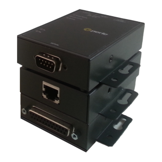
Overview The IOLAN one port units come in various models. Basic Feature Set Models • DG1 RJ45 - RJ45 serial port. • DG1 DB9 - DB9M serial port • DG1 DB25 -DB25F serial port • DG1 TX - Extended Temperature model with a DB9M serial port Secure Feature Set Models •... -
Page 6: Iolan Dg1/Sdg1 (Side View With Barrel Connector)
IOLAN DG1/SDG1 (Side View with Barrel connector) IOLAN DG1 TX/SDG1 TX (Side View with Terminal Block Connector) Ethernet and Serial Ports Ethernet 10/100/1000Base-T Port The Ethernet port provides the standard Gigabit Ethernet interface speeds of 10/100/ 1000 Mbps through twisted pair (UTP) cables of up to 100 meters (328ft) in length. - Page 7 serial (up position). Unless you plan to attach a console to the IOLAN, leave the DIP switch in the serial position. In console mode, this port can be used to provide access to the IOLAN management function using the industry standard CLI command set (see Con- sole Port Mode).
-
Page 8: Led Indicators
LED Indicators Power/Ready State Description Green - solid System Ready Green - flashing System is booting or DIP switch is in console mode Error condition Link 10/100/1000 State Description Green 1000 Mbps Amber 100 /10 Mbps No LAN connection Activity State Description Green... -
Page 9: Installation
Installation General Cautions and Warnings Warning: Power sources must be off prior to beginning the power connection steps. Read the installation instructions before you connect the unit to its power source. Warning: Ensure that the voltage and current ratings of the intended power source are appropriate for the IOLAN as indicated on the product label. -
Page 10: Connecting The Serial Port
Loosen the right screw on the top of the terminal connector block, then insert your negative (-) wire into the right terminal and screw it down tight (.51Nm torque). 4. Turn on power at source. See LED Indicators for power up sequence. Grounding and Power Cord Relief clip If your installation requires additional grounding, follow this procedure. -
Page 11: Connecting Data Ports
6. Choose Start > Control Panel > Systems or equivalent on the Windows Operating System you are using. 7. Click the Hardware tab and choose Device Manager, Expand the Ports (COM & LPT) section. This will expand the drop down to show the number of com ports on your system. - Page 12 Ethernet Connector - 8-pin RJ-45 IOLAN DG1/DG1 TX/SDG1/SDG1 TX Hardware Installation Guide...
-
Page 13: Operation
“Reset” and hold the reset button between 3 and 10 seconds, the IOLAN will reset the configuration to factory default (either the Perle or custom default configuration). If you hold the reset button greater than 10 seconds, then the IOLAN will reset the configura- tion to the Perle factory default configuration. -
Page 14: Configuring The Iolan
SSH, SNMP or the Web interface. Web Manager The Perle Web Manager is an embedded Web based application that provides an easy to use browser interface for configuring and managing the IOLAN. Once an IP address has been assigned/configured on IOLAN, it can be accessed through any standard desktop web browser. -
Page 15: Appendix A - Technical Specifications
Appendix A - Technical Specifications IOLAN DG1/DG1 TX/SDG1/SDG1 TX Port Technical Specifications Nominal Input Voltage 12/24VDC (9-30VDC) Power Supply Options Power via external power 9-30v DC (DG1/SDG1) Terminal block connector (DG1 TX/SDG1 TX) Power Consumption@24V DC (Watts) 2 Watts Power IOLAN over Serial 9-30VDC with DB25F and RJ45 model Operating Temperature -0°C to 55°C... -
Page 16: Appendix B - Mechanical Drawing
Appendix B - Mechanical Drawing RJ45 Serial DB9M Serial IOLAN DG1/DG1 TX/SDG1/SDG1 TX Hardware Installation Guide... - Page 17 DB25F Serial IOLAN DG1/DG1 TX/SDG1/SDG1 TX Hardware Installation Guide...
-
Page 18: Appendix C - Labels (Sample)
Appendix C - Labels (Sample) IOLAN DG1/DG1 TX/SDG1/SDG1 TX Hardware Installation Guide... -
Page 19: Appendix D - Cabling And Connectors
Appendix D - Cabling and Connectors This appendix provides pinouts for the serial DB25F, DB9M, RJ45 port and the Ethernet cable. Connecting Serial Devices Please refer to the pin-out table for your model, and ensure you have the appropriate cable for connecting your serial device to the serial port on the IOLAN. IOLAN DB25 Female Connector EIA-485 EIA-485... - Page 20 IOLAN DB9 Male Connector EIA-422/485 EIA-485 Pinout EIA-232 Full Duplex Half Duplex 1 (in) 2 (in) RxD+ 3 (out) TxD+ DATA+ 4 (out) 6 (in) RxD- 7 (out) 8 (in) TxD- DATA - IOLAN RJ45 Connector EIA-485 EIA-485 Pinout EIA-232 EIA-422 Full Duplex Half Duplex...
- Page 21 Hardware Options The IOLAN contains jumpers that you might need to set before you configure it and put it into production. You can set the Power Out pin, pin 10 to a fixed 5V DC output or to the external adapter output; this can range from 9-30V DC (if an external adapter is shipped with the IOLAN, it has a 12V DC output);...
- Page 22 4. To terminate Serial Port 1 for Full Duplex set DIP switch 1 ON. To terminate for Half Duplex set DIP switch 2 to ON. 5. Close the IOLAN case by replacing the case lid and the two screws. You can now power the IOLAN with the new settings.
-
Page 23: Appendix E - Iolan Maintenance
Appendix E - IOLAN Maintenance • Ensure there is clearance of 50.8mm (2 inches) on all sides of the IOLAN to provide proper airflow through the unit • Do not use solvents or cleaning agents on this unit • Keep vent holes clear of debris •... -
Page 24: Contacting Perle Systems Limited
Contact information for the Perle Technical Assistance Center (PTAC) can be found at the link below. https://www.perle.com/support_services/support_request.shtm Warranty / Registration This product is covered by the Perle IOLAN SDG Warranty. Details can be found at: https://www.perle.com/support_services/warranty.shtml IOLAN DG1/DG1 TX/SDG1/SDG1 TX Hardware Installation Guide...
Need help?
Do you have a question about the IOLAN DG1 TX and is the answer not in the manual?
Questions and answers