
Related Manuals for Perle IOLAN DS1 G


Summary of Contents for Perle IOLAN DS1 G
- Page 1 IOLAN DS1 G/DS1T G /SDS1 G/SDS1T G Hardware Installation Guide Updated: April 2018 Version A.1.04.12.2018 www.perle.com Document Part#:5500418-10 (Rev B)
- Page 2 Modifications to this product not authorized by Perle could void the FCC approval and negate your authority to operate the product. Perle reserves the right to make changes without further notice, to any products to improve reliability, function, or design.
-
Page 3: Table Of Contents
IOLAN DS1 G/SDS1 G (Back View with socket for Barrel connector) ...... -
Page 4: Preface
IOLAN. This document does not cover how to configure your Perle IOLAN SDS1 or DS 1 port. Information to configure your Perle IOLAN DS1 G/DS1T G /SDS1 G/SDS1T G can be found in the IOLAN User’s Guide. -
Page 5: Overview
• SDS1-G25F - 1 port model with a DB25F serial port This chapter discusses the following topics: IOLAN DS1 G/DS1T G/SDS1 G/SDS1T G IOLAN DS1 G/SDS1 G (Back View with socket for Barrel connector) IOLAN DS1T G/SDS1T G (Back View with Terminal Block Connector) Ethernet and Serial Port... -
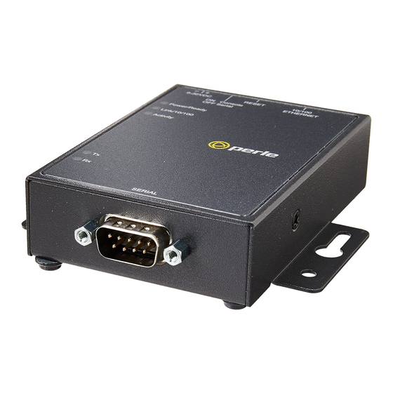
Page 6: Iolan Ds1 G/Sds1 G (Back View With Socket For Barrel Connector)
IOLAN DS1 G/SDS1 G (Back View with socket for Barrel connector) IOLAN DS1T G/SDS1T G (Back View with Terminal Block Connector) Ethernet and Serial Port 10/100/1000Base-T Port The Ethernet port provides the standard gigabit Ethernet interface speeds of 10/100/ 1000 Mbps through twisted pair (UTP) cables of up to 100 meters (328ft) in length. -
Page 7: Led Indicators
Error condition Link 10/100/1000 State Description Green 1000 Mbps Amber 100 /10 Mbps No LAN connection Activity State Description Green Flashes with activity Amber Flashes with activity No LAN connection IOLAN DS1 G/DS1T G/SDS1 G/SDS1T G Hardware Installation Guide... -
Page 8: Installation
Plug the power adapter into a power socket and connect the barrel connector end into the IOLAN. The IOLAN will perform a power up sequence. The Power/Ready LED should show a solid green. See LED Indicators for power up sequence. IOLAN DS1 G/DS1T G/SDS1 G/SDS1T G Hardware Installation Guide... - Page 9 1. Attach the grounding lug to the chassis and secure with the grounding screw provided. See Figure 1. 2. Attach the power cord relief clip as shown in Figure 2. Figure 2 Figure 1 IOLAN DS1 G/DS1T G/SDS1 G/SDS1T G Hardware Installation Guide...
-
Page 10: Connecting The Serial / Console Port
IOLAN in serial mode, but the IOLAN will not display all the messages/information you will get in Console mode. See the IOLAN User’s Guide for more information on the serial port. IOLAN DS1 G/DS1T G/SDS1 G/SDS1T G Hardware Installation Guide... -
Page 11: Rebooting/Resetting The Iolan
2. Once the IOLAN is connected and the link is established, the link LEDs will turn on. These LEDs will indicate whether you have a 10, 100 or 1000 Mbps link to your hub/ switch. See. (LED Indicators) for more details. Ethernet Connector - 8-pin RJ-45 IOLAN DS1 G/DS1T G/SDS1 G/SDS1T G Hardware Installation Guide... -
Page 12: Configuring The Iolan
SSH, SNMP or the Web interface. Web Device Manager The Perle Web Device Manager is an embedded Web based application that provides an easy to use browser interface for configuring and managing the IOLAN. The IOLAN can be accessed through any standard desktop web browser. The IOLAN must have a valid IP address. -
Page 13: Appendix A - Technical Specifications
Appendix A - Technical Specifications IOLAN DS1 G/DS1T G/SDS1 G/SDS1T G Port Technical Specifications 12/24VDC (9-30VDC) Nominal Input Voltage Power via external power 9-30v DC (DS1 G/SDS1 G), 2 Watts, terminal block connector (DS1T G/SDS1T G) Power Supply Options 2 Watts... - Page 14 Contact information for the Perle Technical Assistance Center (PTAC) can be found at the link below. https://www.perle.com/support_services/support_request.shtm Warranty / Registration This product is covered by the Perle IOLAN SDS Warranty. Details can be found at: https://www.perle.com/support_services/warranty.shtml IOLAN DS1 G/DS1T G/SDS1 G/SDS1T G Hardware Installation Guide...
-
Page 15: Appendix B - Mechanical Drawing
Appendix B - Mechanical Drawing RJ45 Serial DB9M Serial IOLAN DS1 G/DS1T G/SDS1 G/SDS1T G Hardware Installation Guide... - Page 16 DB25F Serial IOLAN DS1 G/DS1T G/SDS1 G/SDS1T G Hardware Installation Guide...
-
Page 17: Appendix C - Labels (Sample)
Appendix C - Labels (Sample) IOLAN DS1 G/DS1T G/SDS1 G/SDS1T G Hardware Installation Guide... -
Page 18: Appendix D - Cabling And Connectors
20 (in) TxD+ TxD+ DATA+ TxD- TxD- DATA- RTS+ The Power In pin, pin 12 can be 9-30V DC. The Power Out pin, pin 9, is only available on SDS models. IOLAN DS1 G/DS1T G/SDS1 G/SDS1T G Hardware Installation Guide... - Page 19 TxD- TxD- TxD-/RxD- 6 (in) RxD+ RxD+ 8 (in) RxD- RxD- 9 (out) Power Out Power Out Power Out Power Out The Power In pin, pin 1 can be 9-30V DC. IOLAN DS1 G/DS1T G/SDS1 G/SDS1T G Hardware Installation Guide...
- Page 20 3. To change the Power Pin out, locate P3. For the fixed 5V DC output, jumper pins 1 and 2. For the output to equal the external adapter input, jumper pins 2 and 3. IOLAN DS1 G/DS1T G/SDS1 G/SDS1T G Hardware Installation Guide...
- Page 21 Half Duplex set DIP switch 2 to ON. 5. Close the IOLAN case by replacing the case lid and the two screws. You can now power the IOLAN with the new settings. IOLAN DS1 G/DS1T G/SDS1 G/SDS1T G Hardware Installation Guide...
-
Page 22: Appendix E - Iolan Maintenance
• Keep vent holes clear of debris • If case gets dirty wipe with a dry cloth • Ensure all cables are in good working condition and replace any frayed cables or cables without clips IOLAN DS1 G/DS1T G/SDS1 G/SDS1T G Hardware Installation Guide...
Need help?
Do you have a question about the IOLAN DS1 G and is the answer not in the manual?
Questions and answers