Table of Contents
Advertisement
Bedienungsanleitung...................................................... 9
DE
EN
Operating Manual............................................................ 36
Mode d'emploi ................................................................. 63
FR
Istruzioni per l'uso .......................................................... 90
IT
Rev. 01 / 11.15
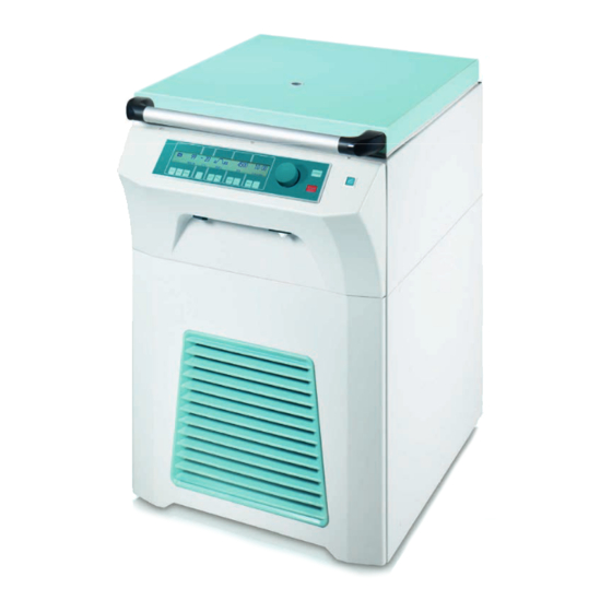
ROTIXA 500 RS
Andreas Hettich GmbH & Co. KG
AB4950DEENFRIT
Advertisement
Table of Contents

Related Manuals for Hettich ROTIXA 500 RS


Summary of Contents for Hettich ROTIXA 500 RS
- Page 1 ROTIXA 500 RS Bedienungsanleitung............9 Operating Manual............36 Mode d'emploi ..............63 Istruzioni per l'uso ............90 Rev. 01 / 11.15 Andreas Hettich GmbH & Co. KG AB4950DEENFRIT...
- Page 2 0482 © 2014 by Andreas Hettich GmbH & Co. KG All rights reserved. No part of this publication may be reproduced without the prior written permission of the copyright owner. Änderungen vorbehalten! , Modifications reserved! , Sous réserve de modifications ! , Con riserva di modifiche! AB4950DEENFRIT / Rev.
- Page 3 The following additional European directives and ordinances have been applied: Machinery Directive 2006/42/EC EMC directive 2004/108/EC Low voltage directive 2006/95/EC RoHS II Directive 2011/65/EC (without involvement of a notified body) Ordinance (EC) No. 1907/2006 (REACH) (without involvement of a notified body) Applied standards: According to the list of applied standards, which is part of the product file.
- Page 4 Standards and regulations which apply to this device The device is a high-end technical product. It is subject to extensive testing and certification procedures according to the following standards and regulations in their respectively valid version: Electrical and mechanical safety for design and final testing: Standard series: IEC 61010 (conform to standards of DIN EN 61010) IEC 61010-1 “Safety requirements for electrical equipment for measurement, control, and laboratory use - Part 1: General requirements”...
-
Page 5: Table Of Contents
Contents How to use these operating instructions .......................38 Symbol meanings ..............................38 Intended use .................................39 Remaining risks ..............................39 Technical specifications............................40 Notes on safety..............................42 Unpacking and setting up the centrifuge.......................44 Delivery checklist ..............................44 Transport and storage ............................45 Transport ...............................45 Storage................................45 Initial operation..............................45 Interface (only for centrifuge with interface) ......................46 Opening and closing the lid ..........................46 12.1... - Page 6 19.1 Centrifugation with time selection ......................52 19.2 Continuous running ............................52 Changing settings during the centrifugation run....................52 Integral RCF ( RCF) ............................52 Displaying the maximum speed of the rotor ......................52 Displaying the maximum RCF of the rotor......................53 Emergency stop ..............................53 Audible signal ..............................53 Interrogating the operating hours ........................53 Setting the date and time ..........................53...
-
Page 7: How To Use These Operating Instructions
How to use these operating instructions Before using the centrifuge, read the operating instructions and observe them. The operating instructions are a part of the device. They must always be kept readily available. If the device is set up at a different location, the operating instructions must be provided with it. Symbol meanings Symbol on the device: Attention, general hazard area. -
Page 8: Intended Use
The centrifuge may only be used by skilled personnel in closed laboratories. The centrifuge is only meant for the above-named purposes. Another use or one which goes beyond this, is considered to be non-intended. The company Andreas Hettich GmbH & Co. KG is not liable for damage resulting from this. -
Page 9: Technical Specifications
Technical specifications Andreas Hettich GmbH & Co. KG Manufacturer D-78532 Tuttlingen Model ROTIXA 500 RS 4950, 4950-70, Type 4950-50 4950-80 Mains voltage ( 10%) 230-240 V 220 V 230-240 V 220 V Mains frequency 50 Hz 60 Hz 50 Hz... - Page 10 Andreas Hettich GmbH & Co. KG Manufacturer D-78532 Tuttlingen Model ROTIXA 500 RS 4950-08, 4950-78, Type 4950-58 4950-88 Mains voltage ( 10%) 208 V Mains frequency 60 Hz Connected load 3800 VA Current consumption 18 A Cooling medium R 404A Max.
-
Page 11: Notes On Safety
The centrifuge may no longer be put into operation when the centrifuging chamber has safety- related damages. With swing-out rotors the trunnions must be regularly lubricated (Hettich Lubricating Grease No. 4051) in order to ensure consistent swinging out of the hangers. - Page 12 Repairs must only be carried out by personnel authorised to do so by the manufacturer. Only original spare parts and original accessories licensed by the Andreas Hettich GmbH & Co. KG company are allowed to be utilised.
-
Page 13: Unpacking And Setting Up The Centrifuge
Unpacking and setting up the centrifuge Remove the packaging. Remove the front wooden beam (a). Fasten the metal rails (b) to the wooden pallet with two nails each. Push the front wooden beam (a) under the metal rails (b) to support these. Roll the centrifuge carefully down from the wooden pallet using the metal rails (b). -
Page 14: Transport And Storage
Transport and storage Transport When the device and accessories are transported, the following ambient conditions must be complied with: Ambient temperature: -20°C to +60°C Relative humidity: 20% to 80%, non-condensing Storage The device and the accessories may only be stored in closed and dry rooms. When the device and accessories are stored, the following ambient conditions must be complied with: Ambient temperature: -20°C to +60°C Relative humidity: 20% to 80%, non-condensing... -
Page 15: Interface (Only For Centrifuge With Interface)
Interface (only for centrifuge with interface) As an option, the device can be equipped with an optical interface. IOIOI The optical interface is labeled with the symbol. OPTICAL The centrifuge can be controlled and data queried via this interface. Opening and closing the lid 12.1 Opening the lid The lid can only be opened when the centrifuge is switched on and the rotor is at rest. -
Page 16: Loading The Rotor
Loading the rotor Standard centrifuge containers of glass will not stand RCF values exceeding 4000 (DIN 58970, pg. 2). Check the rotor for firm seating. With swing-out rotors all rotor positions must be lined with identical hangers. Certain hangers are marked with the number of the rotor position. -
Page 17: Closing Biosafety Systems
Closing biosafety systems In order to guarantee that it is sealed, the lid to the biosafety system has to be firmly closed. In order to prevent the packing ring from twisting when opening and closing the cover, the packing ring must be lightly rubbed with talcum powder or a rubber care product. -
Page 18: Control And Display Devices
Control and display devices 4000 120:30 STOP LOCK1 16.1 Status symbols Lid open. Lid closed. Rotation indicator. The indication appears while the centrifuge is running as long as the rotor is turning. STOP Centrifugation run stopped or finished. Indication after completion of the centrifugation run as long as the rotor is turning. -
Page 19: Entering Centrifugation Parameters
1. Start centrifugation run. The rotation indicator appears. START 2. Acceptance of changes during the centrifugation run. Stop centrifugation run. STOP The rotor decelerates with the preset run-down parameters. Pressing the key twice will initiate an emergency stop. Select program location, parameter PROG-Nr. PROG Calling up of programs. -
Page 20: Braking Step
17.4.3 Braking step Press the key repeatedly until the parameter is displayed. The input field will be displayed inversely. Set the desired step by means of the control knob B-braking steps can only be set for special rotors. 17.4.4 Run-down time If a brake de-energisation speed has been set, it is not possible to set a run-down time. -
Page 21: Centrifugation
Centrifugation When the centrifuge is running, according to EN / IEC 61010-2-020, no persons, dangerous substances or objects may be within the safety margin of 300 mm around the centrifuge. If the permissible weight difference within the rotor loading has been exceeded, the drive shuts down during the start-up, and IMBALANCE / UNWUCHT is displayed. -
Page 22: Displaying The Maximum Rcf Of The Rotor
Displaying the maximum RCF of the rotor Press the key repeatedly until the parameter RCF/RZB is displayed and the input field is shown inversely. Press the key once more and hold it pressed; the maximum RCF of the rotor (RCF-max-Rotor) will be displayed. -
Page 23: Immediate Display Of The Centrifugation Data After Switching On
Immediate display of the centrifugation data after switching on Switch on the mains supply switch. Switch position . Press any key apart from the key when the first visual change appears in the display (inverse display). The STOP centrifugation data will be displayed immediately. Key-operated switch. -
Page 24: Centrifugation Run With Program Linking
31.3 Centrifugation run with program linking Press the key twice in order to select the parameter PR-PART. The input field will be displayed inversely. PROG Set the program location for the first program (XX+) by means of the control knob Press the key. -
Page 25: Relative Centrifugal Force (Rcf)
Relative centrifugal force (RCF) The relative centrifugal force (RCF) is given as a multiple of the acceleration of gravity (g). It is a unit-free value and serves to compare the separation and sedimentation performance. These values are calculated using the formula below: 1,118 1000 1000... -
Page 26: Emergency Release
Emergency release During a power failure the lid cannot be unlocked by motor. An emergency release has to be executed by hand. For emergency release disconnect the centrifuge from the mains. In the case of permanently connected devices, switch off the mains switch to disconnect the mains supply of the device in the building installation and secure it against being switched on again, e.g. -
Page 27: Surface Disinfection
38.1.2 Surface disinfection If infectious materials penetrates into the centrifugal chamber this is to be disinfected immediately. Ingredients of suitable disinfectants: ethanol, n-propanol, ethyl hexanol, anionic tensides, corrosion inhibitors. After using disinfectants, remove the disinfectant residue by wiping with a damp cloth. The surfaces must be dried immediately after disinfecting. -
Page 28: Disinfection
The rotors and accessories must be dried directly after removing the radioactive contaminants. 38.2.4 Trunnions With swing-out rotors the trunnions must be regularly lubricated (Hettich Lubricating Grease No. 4051) in order to ensure consistent swinging out of the hangers. 38.2.5 Rotors and accessories with limited service lives The use of certain rotors, hangers and accessory parts is limited by time. -
Page 29: Autoclaving
38.3 Autoclaving The following accessory can be autoclaved at 121°C / 250°F (20 min): Swing-out rotors Angle rotors made of aluminum Hanger made of metal Lid with biocontainment Stands Reductions Otherwise you must ask the manufacturer. No statement can be made about the degree of sterility. The lids of the rotors and containers must be removed prior to autoclaving. -
Page 30: Faults
Faults If the fault cannot be eliminated with the help of the fault table, please inform Customer Service. Please specify the type of centrifuge and the serial number. Both numbers can be found on the name plate of the centrifuge. Perform a MAINS RESET: Switch off the mains switch (switch position "0"). -
Page 31: Returning Devices
Returning Devices If the device or its accessories are returned to Andreas Hettich GmbH & Co. KG, in order to provide protection for people, the environment and materials, it has to be decontaminated and cleaned before being shipped. We reserve the right to refuse contaminated devices or accessories. -
Page 32: Anhang / Appendix
Anhang / Appendix 42.1 Rotoren und Zubehör / Rotors and accessories 4296 5051 5053 Ausschwingrotor 6-fach / Swing out rotor 6-times max. Laufzyklen /max. cycles: 50000 max.Beladung / max. load: 500 g 5262 5249 5243 5243 + 5242 5247 5227 5257 6316 0526... - Page 33 4296 5051 5053 Ausschwingrotor 6-fach / Swing out rotor 6-times max. Laufzyklen /max. cycles: 50000 max.Beladung / max. load: 500 g 5259 6306 5248 5264 5267 5281 0513 0509 0500 2078 0536 90° Kapazität / capacity 8,5 - 10 4 - 7 1,1-1,4 Maße / dimensions 29 x 115...
- Page 34 4296 5051 5280 5053 Ausschwingrotor 6-fach / Swing out rotor 6-times 1662 1670 1663 1664 1665 1666 1667 1668 1663 1664 90° Kapazität / capacity 3 x 2 4 x 1 mm² 6,2 / 30 8,7 / 60 12,4 / 120 17,5 / 240 8,7 / 60 6,2 / 30...
- Page 35 4296 5092 5093 Ausschwingrotor 6-fach / Swing out rotor 6-times mit Bioabdichtung / with bio-containment 5126 5125 5123 5124 5122 5128 0523 0526 0513 0521 0519 0553 0501 90° Kapazität / capacity 12 x 12 x Maße / dimensions 40 x 115 44 x 100 29 x 115 34 x 100...
- Page 36 4296 5092 5093 Ausschwingrotor 6-fach / Swing out rotor 6-times mit Bioabdichtung / with bio-containment max. Laufzyklen /max. cycles: 30000 max.Beladung / max. load: 500 g 5136 0518 2079 90° 8,5 - Kapazität / capacity 4 – 4,5 7,5 - 8,5 9 - 10 4 - 7 16 x...
- Page 37 4296 5092 5093 5092 Ausschwingrotor 6-fach / Swing out rotor 6-times mit Bioabdichtung / with bio-containment max. Laufzyklen /max. cycles: 30000 max.Beladung / max. load: 500 g 1791 5134 5135 5129 5138 6319 6319 90° 0530 0509 5127 2.7 - 2.6 –...
- Page 38 4294 4295-A 4229-B Ausschwingrotor 4-fach / Swing out rotor 4-times max. Laufzyklen /max. cycles: 15000 (4500 RPM); 50000 (4000RPM) max.Beladung / max. load: 1060 g 4213-93 4214 4214-93 0553 0501 0518 90° Kapazität / capacity 2,7 - 3 7,5 – 8,2 8,5 - 10 4 - 7 Maße / dimensions...
- Page 39 4294 4295-A 4229-B Ausschwingrotor 4-fach / Swing out rotor 4-times max. Laufzyklen /max. cycles: 15000 (4500 RPM); 50000 (4000RPM) max.Beladung / max. load: 1060 g 4233 4220 4222 4223 0551 0578 0500 90° Kapazität / capacity 9 - 10 4 - 7 Maße / dimensions 93 x 137 16 x 92...
- Page 40 4294 4295-A 4229-B 4290 4291 Ausschwingrotor 4-fach / Swing out rotor 4-times max. Laufzyklen /max. cycles: 15000 (4500 RPM); 50000 (4000RPM) max.Beladung / max. load: 1060 g 6322 4223 4232 4245-A 4215 4273 Corning 0509 0513 90° 4 - 7 Kapazität / capacity Maße / dimensions 60 x 162...
- Page 41 4294 4299-N 4236 4299-N Ausschwingrotor 4-fach / Swing out rotor 4-times max. Laufzyklen /max. cycles: 20000 (4500 RPM); 50000 (4000RPM) max.Beladung / max. load: 500 g 4236 + 1485 96-PCR- PCR-Strips Platte / plate 90° LKB-Racks Kapazität / capacity Maße / dimensions 86 x 128 x 86 x 128 x 18 x 46 x...
- Page 42 4294 4257 4254 4255 / 4255-P 8) Ausschwingrotor 4-fach / Swing out rotor 4-times 4259-A 4449 4430 Hitachi- Cor- Nal- 0554 0512 4239 Corning Nunc Racks ning gene 90° Kapazität / capacity 1000 60 x 61,5 x Maße / dimensions 20 x 118 x 70 20 x 118 x 70 97 x 139...
- Page 43 4294 4254 4255 / 4255-P 8) Ausschwingrotor 4-fach / Swing out rotor 4-times max. Laufzyklen /max. cycles: 30000 max. Laufzyklen /max. cycles: 30000 max.Beladung / max. load: 800 g (4500 RPM), 1000 g (4020 RPM), 1200 g (3670 RPM) 4434 0518 90°...
- Page 44 4294 4254 4255 / 4255-P 8) Ausschwingrotor 4-fach / Swing out rotor 4-times max. Laufzyklen /max. cycles: 30000 max. Laufzyklen /max. cycles: 30000 max.Beladung / max. load: 800 g (4500 RPM), 1000 g (4020 RPM), 1200 g (3670 RPM) 4439 4440 4441 4442...
- Page 45 4282 4285-A Ausschwingrotor 2-fach / Swing out rotor 2-times max. Laufzyklen /max. cycles: 12000 (3600 RPM), 30000 (3000 RPM) max.Beladung / max. load: 2320 g 4281 4281 1485 Microtest- platten / plate 96-PCR-Platte / plate PCR-Strips Terasaki 90° Kapazität / capacity Maße / dimensions 86x128x17,5 86x128x22...
- Page 46 4246 Winkelrotor 6-fach / 1454 1446 1447 1466 1451 Angle rotor 6-times 0513 0546 0519 0545 0509 0547 0539 0538 45° mit Bioabdichtung / with bio-containment Kapazität / capacity 7,5 - 8,5 9 - 10 38 x 38 x 24 x 26 x Maße / dimensions 29 x 115...
- Page 47 4246 4316 Winkelrotor 6-fach / 1449 4317 Winkelrotor 6-fach / Angle rotor 6-times Angle rotor 6-times 0533 0532 2078 0536 45° mit Bioabdichtung / 45° with bio-containment Kapazität / capacity Kapazität / capacity 11 x 11 x Maße / dimensions 10,7 x 36 10 x 60 Maße / dimensions...
- Page 48 4266 Winkelrotor 6-fach / 5641 5642 5643 5644 5646 Angle rotor 6-times 5127 0545 0519 0546 0547 0549 0518 0539 0538 25° mit Bioabdichtung / with bio-containment Kapazität / capacity 26 x 24 x 38 x 38 x Maße / dimensions 61 x 122 16 x 80 29 x 107...
Need help?
Do you have a question about the ROTIXA 500 RS and is the answer not in the manual?
Questions and answers