Hettich ROTOFIX 32 A Operating Instructions Manual
Hide thumbs
Also See for ROTOFIX 32 A:
- Operating instructions manual (82 pages) ,
- Operating instructions manual (64 pages) ,
- Operating instructions manual (62 pages)

Subscribe to Our Youtube Channel
Related Manuals for Hettich ROTOFIX 32 A


Summary of Contents for Hettich ROTOFIX 32 A
- Page 1 ROTOFIX 32 A Operating Instructions............ 4 Rev. 05 / 12.2022 Andreas Hettich GmbH & Co. KG AB1206EN_SA...
- Page 2 Fig. 1 Fig. 2 ROTOFIX 32 A 2/46 Rev. 05 / 12.2022 AB1206EN_SA...
- Page 3 Single Registration Number: DE-MF-000010680 © 2006 by Andreas Hettich GmbH & Co. KG All rights reserved. No part of this publication may be reproduced without the prior written permission of the copyright owner. Änderungen vorbehalten! , Modifications reserved! , Sous réserve de modifications ! , Con riserva di modifiche! AB1206EN_SA / Rev.
-
Page 4: Table Of Contents
Contents Use according to specification ..........................6 Remaining risks ..............................6 Technical specifications............................6 Notes on safety...............................7 Symbol meanings ..............................9 Delivery checklist ..............................10 Unpacking the centrifuge ............................10 Transport and storage ............................10 Transport ...............................10 Storage................................10 Initial operation ..............................11 Opening and closing the lid ..........................11 10.1 Opening the lid............................ - Page 5 26.1.3 Removal of radioactive contaminants ....................21 26.2 Rotors and Attachments..........................22 26.2.1 Cleaning and care..........................22 26.2.2 Disinfection ............................22 26.2.3 Removal of radioactive contaminants ....................22 26.2.4 Trunnions ............................23 26.2.5 Rotors and accessories with limited service lives ................23 26.3 Autoclaving ..............................23 26.4 Centrifuge containers ..........................23 Faults ................................24 Change mains input fuses ..........................25 Returning Devices .............................25...
-
Page 6: Use According To Specification
Intended use also includes observing all instructions in the Operating Manual and compliance with the required inspection and maintenance work. Any other use or use beyond this is considered improper. Andreas Hettich GmbH & Co. KG shall not be liable for any damage arising from this. -
Page 7: Notes On Safety
The centrifuge may no longer be put into operation when the centrifuging chamber has safety- related damages. With swing-out rotors the trunnions must be regularly lubricated (Hettich Lubricating Grease No. 4051) in order to ensure consistent swinging out of the hangers. - Page 8 Repairs must only be carried out by personnel authorised to do so by the manufacturer. Only original spare parts and original accessories licensed by the Andreas Hettich GmbH & Co. KG company are allowed to be utilised.
-
Page 9: Symbol Meanings
Symbol meanings Symbol on the device: Attention, general hazard area. Symbol on the device: Observe operating instructions. This symbol indicates that the user must observe the operating instructions provided. Symbol in this document: Attention, general hazard area. This symbol refers to safety relevant warnings and indicates possibly dangerous situations. The non-adherence to these warnings can lead to material damage and injury to personal. -
Page 10: Delivery Checklist
Delivery checklist The following items and accessories are delivered with the centrifuge: Connecting cable Fuses Lubricating grease for trunnions Hex. pin driver Release pin Notes on moving the equipment safely Operating instructions The rotor(s) and associated accessories are included in the delivery in the quantity. Unpacking the centrifuge Lift the carton upward and remove the padding. -
Page 11: Initial Operation
Initial operation Remove the transportation safety device from the bottom of the housing, see sheet ”Transportation safety device". Position the centrifuge in a stable and level manner in a suitable place. During set-up, the required safety margin of 300 mm around the centrifuge is to be kept according to EN / IEC 61010-2-020. When the centrifuge is running, according to EN / IEC 61010-2-020, no persons, dangerous substances or objects may be within the safety margin of 300 mm around the centrifuge. -
Page 12: Installation And Removal Of The Rotor
Installation and removal of the rotor 11.1 Rotor with clamping nut Rotor installation: Dirt particles between the motor shaft and rotor prevent the rotor from having a perfect seat and cause it to run unsteadily. Clean the motor shaft (C) and the bore of the rotor (A) and then apply a thin coat of grease to the motor shaft. -
Page 13: Inserting And Removing Hangers Into/From The Rotor
Inserting hangers in the rotor: Check the rotor to make sure it is seated firmly. Grease the lifting lug (C) (Hettich lubricating grease, no. 4051). Insert hangers (A) into the rotor. While doing so, make sure that the lifting lugs (C) are in the grooves (B) of the hangers. -
Page 14: Loading The Rotor
Loading the rotor Standard centrifuge containers of glass will not stand RCF values exceeding 4000 (DIN 58970, pg. 2). Check the rotor for firm seating. With swing-out rotors all rotor positions must be lined with identical hangers. Certain hangers are marked with the number of the rotor position. -
Page 15: Closing Biosafety Systems
The maximum filling quantity for the centrifuge containers specified by the manufacturer must not be exceeded. In the case of angle rotors, the centrifuging Fluid vessels may only be filled so far that no fluid can be expelled from them while the centrifuge is running. -
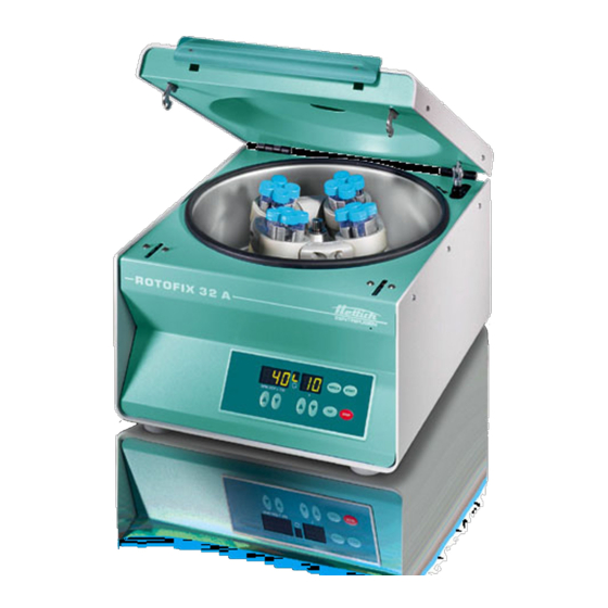
Page 16: Control And Display Elements
Control and display elements See figure on page 2. Fig. 2: Display and control panel 17.1 Symbols on the control panel Rotation indicator. The rotation indicator lights up and rotates anticlockwise while the rotor is turning. When the rotor is stationary, the status of the lid is displayed by symbols in the rotation indicator: Symbol : Lid open Symbol... -
Page 17: Setting The Brake Step
Setting the brake step Switch off the mains switch. Keep the key beneath the speed indicator and the key pressed simultaneously. Switch on the mains switch and release the keys again. The speed indicator shows the machine version and the time indicator shows the set brake step: e.g.: IMPULS START IMPULS... -
Page 18: Centrifugation With Preselected Time
20.1 Centrifugation with preselected time Set the desired speed with the keys beneath the speed indicator. Set the desired time with the keys beneath the time indicator. Press the key . The rotation indicator appears while the rotor is turning. The time is displayed in minutes. -
Page 19: Acoustic Signal
Acoustic signal The acoustic signal sounds: After a disturbance occurs, in 2 second intervals. After completion of a centrifugation run and rotor standstill in 30 second intervals. The acoustic signal is stopped by opening the lid or pressing any key. The acoustical signal can be activated or deactivated as follows when the rotor is at a standstill: Switch off the mains switch. -
Page 20: Centrifugation Of Materials Or Mixtures Of Materials With A Density Higher Than 1.2 Kg/Dm
Centrifugation of materials or mixtures of materials with a density higher than 1.2 kg/dm When centrifuging with maxim revolutions per minute the density of the materials or the material mixtures may not exceed 1.2 kg/dm The speed must be reduced for materials or mixtures of materials with a higher density. The permissible speed can be calculated using the following formula: Reduced speed... -
Page 21: Maintenance And Servicing
Maintenance and servicing The device can be contaminated. Pull the mains plug before cleaning. Before any other cleaning or decontamination process other than that recommended by the manufacturer is applied, the user has to check with the manufacturer that the planned process does not damage the device. Centrifuges, rotors and accessories must not be cleaned in rinsing machines. -
Page 22: Rotors And Attachments
26.2 Rotors and Attachments 26.2.1 Cleaning and care In order to avoid corrosion and changes in materials, the rotors and accessories have to be cleaned regularly with soap or with a mild cleaning agent and a moist cloth. Cleaning is recommended at least once a week. Contaminants must be removed immediately. -
Page 23: Trunnions
26.2.4 Trunnions With swing-out rotors the trunnions must be regularly lubricated (Hettich Lubricating Grease No. 4051) in order to ensure consistent swinging out of the hangers. 26.2.5 Rotors and accessories with limited service lives The use of certain rotors, hangers and accessory parts is limited by time. -
Page 24: Faults
Faults If the fault cannot be eliminated with the help of the fault table, please inform Customer Service. Please specify the type of centrifuge and the serial number. Both numbers can be found on the name plate of the centrifuge. Perform a MAINS RESET: Switch off the mains switch (switch position "0"). -
Page 25: Change Mains Input Fuses
Before returning the device, a transport securing device has to be installed. If the device or its accessories are returned to Andreas Hettich GmbH & Co. KG, in order to provide protection for people, the environment and materials, it has to be decontaminated and cleaned before being shipped. -
Page 26: Disposal
The device can be disposed of via the manufacturer. A Return Material Authorisation (RMA) form must always be requested for a return. If necessary, contact the Technical Service Department of the manufacturer: Andreas Hettich GmbH & Co. KG Föhrenstrasse 12 78532 Tuttlingen, Germany Phone: +49 7461 705 1400 Email: service@hettichlab.com... -
Page 27: Anhang / Appendix
Anhang / Appendix 31.1 Rotoren und Zubehör / Rotors and accessories 1324 1490 1492 Ausschwingrotor 4-fach / Swing out rotor 4-times mit Bioabdichtung / with bio-containment 1329 1329 1330 0761 0765 0526 0500 0507 0519 0534 0535 90° 7,5 - Kapazität / capacity 15 x 16 x... - Page 28 1324 1490 1492 Ausschwingrotor 4-fach / Swing out rotor 4-times mit Bioabdichtung / with bio-containment 1329 1351 1363 1365 1383 0518 0578 2078 0536 0533 0501 90° 2,7 - 3 Kapazität / capacity 12 x 12 x 17 x 100 11 x 38 10,7 x 36 25 x 90...
- Page 29 1324 1490 1492 Ausschwingrotor 4-fach / Swing out rotor 4-times mit Bioabdichtung / with bio-containment 1459 4416 4417 6311 6318 1356 1457 0546 0545 0509 ---- Falcon ® 90° Kapazität / capacity 4 – 5,5 7,5 – 8,5 1,1 – 1,4 15 x 75 15 x 92 29 x 107...
- Page 30 1324 1398 Ausschwingrotor 4-fach / Swing out rotor 4-times 1482A 0500 0507 90° 2,6 –2,9 4 – 4,5 9 – 10 4 - 7 Kapazität / capacity 13 x 65 15 x 75 16 x 92 15 x 102 17 x 100 16 x 75 14 x 100 17 x 100...
- Page 31 1324 1398 Ausschwingrotor 4-fach / Swing out rotor 4-times 1486 90° Kapazität / capacity 2,6 – 3,4 2,7 – 3 4,5 - 5 1,6 -5 4 –7 13 x 65 11 x 66 11 x 92 13 x 90 13 x 75 13 x 100 Maße / dimensions Anzahl p.
- Page 32 1624 1366 1308 1345 1346 Ausschwingrotor 4-fach / Swing out rotor 4-times 1326 1327 1357 5277 Rhe- 0521 2078 0536 90° Kapazität / capacity 34 x 100 31 x 100 21 x 100 12 x 60 10 x 60 6 x 45 11 x 38 Maße / dimensions Anzahl p.
- Page 33 1624 1481 1492 Ausschwingrotor 4-fach / Swing out rotor 4-times mit Bioabdichtung / with bio-containment 1329 1330 1331 1339 1343 1347 Rhe- 0500 0507 0519 0521 0509 90° 7,5 - Kapazität / capacity 15 x 16 x 10 x 10 x 14 x 100 17 x 100 24 x 100...
- Page 34 1624 1481 1492 Ausschwingrotor 4-fach / Swing out rotor 4-times mit Bioabdichtung / with bio-containment 1383 0501 90° Kapazität / capacity 1,6 – 5,0 4,5 - 5,0 2,7 – 3 2,6 – 3,4 4 – 7 12 x 12 x 12 x 75 13 x 75 11 x 92...
- Page 35 1624 1481 1492 Ausschwingrotor 4-fach / Swing out rotor 4-times mit Bioabdichtung / with bio-containment 1459 4416 4417 1363 1365 0761 0765 0534 0546 0545 0526 0535 90° 4 - 5,5 7,5 - 8,5 Kapazität / capacity 15 x 75 15 x 92 29 x 107 26 x 95...
- Page 36 1611 1131 1132 Ausschwingrotor 8-fach / Swing out rotor 8-times 0501 2079 90° 2,6 – 3,4 2,7 - 3 1,6 – 5,0 4,0 – 5,5 4 - 7 Kapazität / capacity 12 x 82 13 x 65 11 x 66 13 x 75 17 x 70 15 x 75...
- Page 37 1620A 1449 1451 1403 Winkelrotor 6-fach / Angle rotor 6-times 0518 2078 0536 35° 9 - 10 7,5 - 8,5 8,5 - 10 Kapazität / capacity 10,7 10 x 11 x 38 12 x 40 17 x 100 16 x 92 15 x 92 16 x 100 15 x 102...
- Page 38 1620A Winkelrotor 6-fach / Angle rotor 6-times SK 63.98 0547 0549 0501 35° Kapazität / capacity 1,6 - 5 2,6 – 3,4 38 x 106 38 x 106 12 x 82 13 x 75 13 x 65 Maße / dimensions 12/13 x 75 Anzahl p.
- Page 39 1628 1127 Ausschwingrotor 12-fach / Swing out rotor 12-times 55° mit / with 1127 1,6 – 5,0 2,6 – 3,4 2,7 - 3 Kapazität / capacity 13 x 75 13 x 65 11 x 66 Maße / dimensions 12 / 13 x 75 Anzahl p.
- Page 40 1613 Winkelrotor 12-fach / Angle rotor 12-times 0518 0509 0507 35° 4 - 7 4,5 - 5 7,5 – 8,5 9 - 10 Kapazität / capacity 17 x 100 17 x 120 13 x 100 13 x 90 11 x 92 15 x 92 16 x 92 Maße / dimensions...
- Page 41 1613 1063-6 1054-A 1054-A /0701 Winkelrotor 12-fach / Angle rotor 12-times 6305 35° 1,6 - 5 Kapazität / capacity 13 x 75 12 x 60 10 x 88 10,7 x 36 Maße / dimensions Anzahl p. Rotor / number p. rotor 6000 6000 6000...
- Page 42 1418 1467 Winkelrotor 8-fach / Angle rotor 8-times 1054-A 1054-A /0701 + 0716 0553 45° 1,1 – 1,4 2,7 - 3 2,6 – 3,4 1,6 - 5 Kapazität / capacity 12 x 60 12 x 75 8 x 66 11 x 66 13 x 65 13 x 75 13 x 75...
- Page 43 1624 1661 + 1660 1660 1680 Ausschwingrotor 4-fach / Swing out rotor 4-times 1670 1285 1662 nur ohne Deckel / without lid 1661 1665 1666 1667 1668 1671 1672 1673 90° Objektträger/ 3 x 2 4 x 1 [1] 0,5 [1] 0,5 [1] 0,5 Kapazität / capacity...
- Page 44 1626 1661 + 1660 Ausschwingrotor 6-fach / Swing out rotor 6-times 1662 1670 1663 1664 1665 1666 1667 1668 1663 1664 90° 3 x 2 4 x 1 Kapazität / capacity 6,2 / 30 8,7 / 60 12,4 / 120 17,5 / 240 8,7 / 60 6,2 / 30...
- Page 45 1626 1661 + 1660 1648 1680 Ausschwingrotor 6-f ach / Ausschwingrotor 8-fach / Swing out rotor 6-times Swing out rotor 8-times 1470 1662 1471 1475 1671 1672 1673 90° 90° 1 x 8 2 x 8 [1] 0,5 [1] 0,5 [1] 0,5 Kapazität / capacity Kapazität / capacity...
- Page 46 1515-A 1524 Rotor 12-fach 1531 / 1534 1532 1536 1538 1537 1539 90° Kapazität / capacity mm² 6 / 28,3 6 / 28,3 6 / 28,3 Maße / dimensions Maße (L x B) / 13,4 x 22 dimensions (L x W) Anzahl p.
Need help?
Do you have a question about the ROTOFIX 32 A and is the answer not in the manual?
Questions and answers