Table of Contents
Advertisement
Advertisement
Table of Contents

Subscribe to Our Youtube Channel
Related Manuals for Brookfield DVE


Summary of Contents for Brookfield DVE
-
Page 1: Operating Instructions
BROOKFIELD DVE Digital Viscometer Operating Instructions Manual No. M15-356-B0916 Instrumentation & Specialty Controls Division 11 Commerce Boulevard, Middleboro, MA 02302 : 508-946-6200 or 800-628-8139 (USA excluding MA) : 508-946-6262 Internet http://www.brookfieldengineering.com... -
Page 3: Table Of Contents
Appendix A - Viscosity Ranges ..................24 Appendix B - Variables in Viscosity Measurements ............ 28 Appendix C - Spindle Entry Codes and SMC/SRC Values ..........30 Appendix D - Spindle Entry Codes and Range Coefficients ......... 33 Appendix E - Calibration Check Procedures ..............35 Appendix F - The Brookfield Guard Leg ............... 42 Appendix G - Laboratory Stands with Parts Identification .......... 44 Appendix H - Fault Diagnosis and Troubleshooting ............ 46 Appendix I - Online Help and Additional Resources ........... 47 Appendix J - Warranty Repair and Services ..............48 Viscosity Test Report .................. -
Page 5: Introduction
DVE and can be downloaded in pdf form from the Brookfield website, www.brookfieldengineering.com. The principle of operation of the DVE is to rotate a spindle (which is immersed in the test fluid) through a calibrated spring. The viscous drag of the fluid against the spindle is measured by the spring deflection. -
Page 6: Components
Please check to be sure that you have received all components, and that there is no damage. If you are missing any parts, please notify AMETEK Brookfield or your local authorized dealer immediately. Any shipping damage must be reported to the carrier. -
Page 7: Components And Dimensions
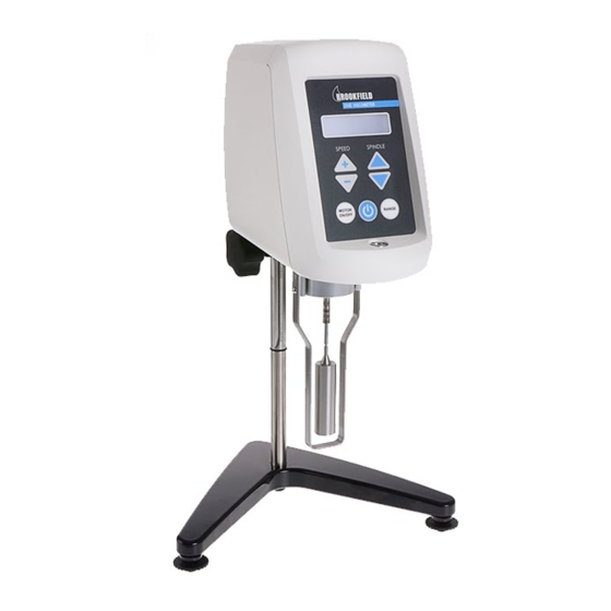
I.3 Components and Dimensions DVE Viscometer Model A Laboratory Stand Shipping Spindle Set LV Guard AV-6 Power Supply Figure I-I AMETEK Brookfield Page 7 Manual No. M15-356-B0916... - Page 8 9 15/32 [24.1 cm] 13 13/32 [34.1 cm] DVE VISCOMETER 7 51/64 5 3/16 [19.8 cm] [13.2 cm] 14 7/8 [37.8 cm] B-21Y RV GUARD LEG 16 9/32 ASSEMBLY [41.3 cm] 7 3/8 [18.7 cm] 3 3/16 [8.1 cm] VS-1...
-
Page 9: Specifications
Users within the European Union: Please contact your dealer or the local authorities in charge of waste management on how to dispose of this product properly. All AMETEK Brookfield offices and our network of representatives and dealers can be found on our website: www.brookfieldengineering.com. -
Page 10: Installation
The Viscometer must be leveled. The level is adjusted using the three leveling screws on the base. Adjust so that the bubble level on the front of the DVE is centered within the circle. Note: Check level periodically during use. - Page 11 The instrument can be identified by the item or model number. The item and model numbers appear on the Serial tag located at the back of the instrument. Below is an explanation on how to read these numbers. B C D A - DVE Designation Item DVEERVTJ0 B - Torque Range (LV, RV, HA, HB)
-
Page 12: Safety Symbols And Precautions
I.7 Key Functions Figure I-4 shows the control keys on the face of the DVE Viscometer. Each key’s function is described below. For additional navigation instructions, see Section II.2. -
Page 13: Preventative Maintenance And Cleaning
Clean with dry, non-abrasive cloth. Do not use solvents or cleaners. Immersed Components: Spindles and guard leg are made of stainless steel. Clean with non-abrasive cloth and solvent appropriate for sample material that is not aggressive to stainless steel. AMETEK Brookfield Page 13 Manual No. M15-356-B0916... -
Page 14: Getting Started
Options menu is accessed from the Default screen. All user input is made through the keypad (see Section I.7 for a description of Key Functions). Several keys are used on the DVE to access the Options menu. The function of each key is indicated below: Press and hold the SPEED + and SPINDLE (Up arrow) keys simultaneously to go to the Options screen. -
Page 15: Ii.3 Spindle Selection
Spindles can be identified by the number on the side of the spindle coupling nut. The DVE requires a spindle entry code number to calculate viscosity values. The two-digit code for each spindle can be found in Appendix D. - Page 16 The DVE will begin to calculate using the new spindle parameters after the spindle number is shown in the display. As the spindle number is changed, the Full Scale Range value will also change to reflect the new spindle number entered (refer to Section III.3).
-
Page 17: Ii.4 Speed Selection
II.4 Speed Selection There are 18 rotational speeds available on the DVE Viscometer. These speeds correspond to the standard LVF, LVT, RVF, RVT, HAT and HBT Dial Viscometer models, and they are combined sequentially (see Table II-1). Note: Speed changes are not instantaneous when motor is on. There will be some acceleration/deceleration time as speed changes are entered. - Page 18 Brookfield publication “ More Solutions to Sticky Problems” The DVE Viscometer will remember the selected speed and spindle when power is turned off. On start-up, the viscometer will be set to the previously selected spindle and speed. Please see Brookfield publication, “...
-
Page 19: Ii.6 Range
DVE Viscometer. This value represents the measured viscosity which will be displayed when the instrument’s % torque reading is at 100. Pressing the key at any time will cause the current viscosity display to change and show the maximum viscosity. -
Page 20: Ii.7 Out Of Range
II.7 Out of Range The DVE gives indications for out of specification or out of range operation. When torque % readings exceed 100.0% (over range), the display changes to that shown in Figure -10. You must either reduce the speed or use a smaller size spindle to correct this condition. Audible noise may be heard in this case. -
Page 21: Making Viscosity Measurements
Reading Viscometer and the DV series of Digital Viscometers. If you have experience with other Brookfield equipment, this section will give you the quick steps necessary for taking a viscosity reading. If you have not used a Brookfield Viscometer before, skip this section and go to Section III.2 for a detailed description. -
Page 22: Iii.3 Selecting A Spindle/Speed
III.3 Selecting a Spindle/Speed The DVE has the capability of measuring viscosity over a wide range (for example, the DVERV can measure fluids within the range of 100-13,000,000 cP) (see Appendix A). This range is achieved through the use of several spindles over many speeds. - Page 23 Viscometer. Be sure the motor is off when changing spindles. Enter the spindle number into the DVE Viscometer by using the SPINDLE UP/DOWN key. Select the speed of rotation by using the SPEED UP/DOWN key. To make a viscosity measurement, press the MOTOR ON/OFF key. Allow time for the indicated reading to stabilize.
-
Page 24: Appendix A - Viscosity Ranges
320-3200 3200-32000 170400 - 1704000 Notes: 1) 1 Pa = 10 dyne/cm 2) 1 cP = 1 mPa•s 3) Possibility of turbulence at speeds above 10 RPM may give artificially higher viscosity readings. AMETEK Brookfield Page 24 Manual No. M15-356-B0916... - Page 25 YULA-15 or 15Z 1 - 2,000 7 - 2,000 13 - 2,000 52 - 2,000 1.22N ULA-DIN-Y 1 - 3,800 11 - 5,000 22 - 5,000 85 - 2000 1.29N N = RPM AMETEK Brookfield Page 25 Manual No. M15-356-B0916...
- Page 26 Viscosity measurements should be taken under laminar flow conditions, not under turbulent flow conditions. The first consideration has to do with the accuracy of the instrument. All DVE Viscometers have a Full Scale Range allowable error of (+/-) 1% of any spindle/speed in use. We discourage taking readings below 10% of range because the potential viscosity error of (+/-) 1% is a relatively high number compared to the instrument reading.
- Page 27 15 cP at 60 RPM 1) No. 1 LV Spindle: 100 cP at 200 RPM 2) No. 2 LV Spindle: 100 cP at 50 RPM (optional spindle available from Brookfield) 3) No. 1 RV Spindle: 0.85 cP at 60 RPM 4) UL Adapter: Turbulent conditions may exist in these situations whenever the RPM/cP ratio exceeds the values listed above.
-
Page 28: Appendix B - Variables In Viscosity Measurements
Rheopectic - This is essentially the opposite of thixotropic behavior, in that the fluid's viscosity increases with time as it is sheared at a constant rate. AMETEK Brookfield Page 28 Manual No. M15-356-B0916... - Page 29 The Brookfield publication, “More Solutions to Sticky Problems”, includes a more detailed discussion of rheological properties and non-Newtonian behavior. Viscometer Related Variables Most fluid viscosities are found to be non-Newtonian. They are dependent on Shear Rate and the spindle geometry conditions. The specifications of the viscometer spindle and chamber geometry will affect the viscosity readings.
-
Page 30: Appendix C - Spindle Entry Codes And Smc/Src Values
When using a standard Brookfield Digital Viscometer, each spindle has a two digit entry code which is entered via the keypad on the DVE. The entry code allows the DVE to calculate Viscosity. Each spindle has two constants which are used in these calculations. The Spindle Multiplier Constant (SMC) used for viscosity and shear stress calculations, and the Shear Rate Constant (SRC), used for shear rate and shear stress calculations. - Page 31 0.48 SC4-16 0.29 SC4-18 1.32 SC4-21 0.93 SC4-25 0.22 SC4-27 0.34 SC4-28 0.28 SC4-29 0.25 SC4-31 0.34 SC4-34 0.28 V-71 2.62 V-72 11.1 V-73 53.5 V-74 V-75 Table C-1 (Continued from previous page) AMETEK Brookfield Page 31 Manual No. M15-356-B0916...
- Page 32 2.5HA DVEHB Table C-2 The full scale viscosity range for any DVE model and spindle may be calculated using the equation: Full Scale Viscosity Range [cP] = TK * SMC * 10,000 where: = DVE Torque Constant from Table C-2...
-
Page 33: Appendix D - Spindle Entry Codes And Range Coefficients
3,200,000 37,500 1,000,000 2,000,000 8,000,000 93,750 375,000 4,000,000 8,000,000 32,000,000 64,000 128,000 512,000 6,000 320,000 640,000 2,560,000 30,000 1,280,000 2,560,000 10,240,000 120,000 LV4 or 4B2 600,000 6,400,000 12,800,000 51,200,000 1,200,000 12,800,000 25,600,000 102,400,000 AMETEK Brookfield Page 33 Manual No. M15-356-B0916... - Page 34 1,280,000 5,120,000 V-71 26,200 52,400 209,600 2,456 V-72 111,000 222,000 888,000 10,404 V-73 535,000 1,070,000 4,280,000 50,146 V-74 508,954 5,430,000 10,860,000 43,440,000 V-75 199,645 2,130,000 4,260,000 8,520,000 Table D-1 (Continued from previous page) AMETEK Brookfield Page 34 Manual No. M15-356-B0916...
-
Page 35: Appendix E - Calibration Check Procedures
• DIN Adapter • Spiral Adapter The accuracy of the DVE is verified using viscosity standard fluids, which are available from AMETEK Brookfield or your local authorized dealer. Viscosity standards are Newtonian, and therefore, have the same viscosity regardless of spindle speed (or shear rate). Viscosity standards, calibrated at 25°C, are shown in Table F-1 (Silicone Oils) and Table F-2 (Mineral Oils). - Page 36 Table F-2 Brookfield Viscosity Standard Fluid - General Information The calibration of the Brookfield viscometer can be verified through the use of calibrated viscosity standard fluids. The Brookfield viscometer operates through the use of a calibration torque sensor with variable spindle geometry and rotational speeds. If the viscometer passes a calibration check...
- Page 37 Follow these steps using one of the recommended spindles to verify calibration of your instrument. 1) Place the viscosity standard fluid (in the proper container) into the water bath. 2) Lower the DVE into measurement position (with guard leg if LV or RV series viscometer is used).
- Page 38 3) Put the spindle into the test fluid and attach the extension link, coupling nut and free hanging spindle (or directly attach the solid shaft spindle) to the DVE. 4) Allow sufficient time for the viscosity standard, sample chamber and spindle to reach test temperature.
- Page 39 1) Put the proper amount of viscosity standard fluid into the UL closed Tube. (Refer to the UL Adapter instruction manual). 2) Attach the spindle (with coupling nut) onto the DVE. 3) Attach the tube to the mounting bracket. 4) Lower the tube into the water bath reservoir, or if using the ULA-40Y water jacket, connect the inlet/outlets to the bath external circulating pump.
- Page 40 1) Place the viscosity standard fluid (in the proper container) into the water bath. 2) Attach the spindle to the viscometer. Attach chamber (SA-1Y) and clamp to the viscometer. 3) Lower the DVE into measurement position. Operate the viscometer at 50 or 60 RPM until the chamber is fully flooded.
- Page 41 4) Therefore, any viscosity reading between 11,634.4 and 12,879.6 cP indicates that the viscometer is operating correctly. Any reading outside these limits may indicate a viscometer problem. Contact the Brookfield technical sales department or your local authorized dealer with test results to determine the nature of the problem.
-
Page 42: Appendix F - The Brookfield Guard Leg
The current guard leg is a band of metal in the shape of the letter U with a bracket at the top that attaches to the pivot cup of a Brookfield Viscometer/Rheometer. A guard leg is supplied with all LV and RV series instruments, but not with the HA or HB series. - Page 43 The guard leg is a part of the calibration check of the Brookfield LV and RV series Viscometer. Our customers should be aware of its existence, its purpose and the effect that it may have on data. With this knowledge, the viscometer user may make modifications to the recommended method of operation to suit their needs.
-
Page 44: Appendix G - Laboratory Stands With Parts Identification
Screw, 5/16-18 x 1" lg. slotted head VS-3 Leveling Screws, Model A, S and Q * Optional 18" rod available N/A Not for individual purchase † Includes screw and washer (Items 6 and 7) AMETEK Brookfield Page 44 Manual No. M15-356-B0916... - Page 45 Center the Viscometer relative to the stand base and retighten the jam nut as required. Refer ring to the Viscometer bubble level, adjust the leveling screws until the instrument is level. Operation Rotate the Up/Down Knob to raise or lower the viscometer. AMETEK Brookfield Page 45 Manual No. M15-356-B0916...
-
Page 46: Appendix H - Fault Diagnosis And Troubleshooting
Verify that calibration check procedures were followed exactly. If the unit is found to be out of tolerance, the unit may be in need of service. See Appendix J for details on how to return your viscometer. AMETEK Brookfield Page 46 Manual No. M15-356-B0916... -
Page 47: Appendix I - Online Help And Additional Resources
Brookfield is involved with a satellite website that should be your first stop in viscosity research. This site serves as a library of interviews with experts in the viscosity field as well as Brookfield technical articles and conversion charts. Registration is required so that you can be notified of upcoming interviews and events, however, this information will not be shared with other vendors, institutions, etc. -
Page 48: Appendix J - Warranty Repair And Services
Telephone: (508) 946-6200 Fax: (508) 923-5009 www.brookfieldengineering.com For repair or service outside the United States, consult Brookfield or the authorized dealer from whom you purchased the instrument. For repair or service in the United Kingdom return to: AMETEK (GB) Limited... -
Page 49: Viscosity Test Report
Viscosity Test Report...
Need help?
Do you have a question about the DVE and is the answer not in the manual?
Questions and answers