Table of Contents
Advertisement
Quick Links
Advertisement
Table of Contents

Related Manuals for Brookfield KF40


Summary of Contents for Brookfield KF40
- Page 1 BROOKFIELD KF40 Falling Ball Viscometer Operating Instructions Manual No. M19-354 INSTRUMENTATION & SPECIALTY CONTROLS DIVISION 11 Commerce Boulevard, Middleboro, MA 02302 : 508-946-6200 or 800-628-8139 (USA excluding MA) : 508-946-6262 http://www.brookfieldengineering.com Internet...
-
Page 3: Table Of Contents
Table of Contents I. INTRODUCTION ....................5 I.1 Components..............................5 I.2 Specifications ..............................6 I.3 Details on Viscosity Measurement Range ....................7 I.4 Description of the Equipment ........................7 I.5 Safety Symbols and Precautions ......................10 I.6 Cleaning ................................. 10 II. GETTING STARTED ....................11 II.1 Choice of Balls .............................. 11 II.2 Filling the Sample Tube .......................... -
Page 5: Introduction
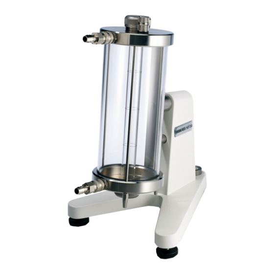
The measuring principle, according to Höppler, is to determine the falling time of a ball in a cylindrical glass tube filled with liquid. The working angle of the falling tube in the KF40 are variable at 80°, 70°, 60° and 50° relative to horizontal. The water jacket, surrounding the falling tube, when connected to a Brookfield circulating temperature bath provides for precise temperature control of the sample. -
Page 6: Specifications
±0.6% if the reading when used with balls 2 and 3. Dimensions: 180 mm x 220 mm x 330 mm Weight: 6.4 lbs, 2.9 kg (empty glass tube and empty waterbath jacket) M19-354 Page 6 ©2019 AMETEK Brookfield Inc. All rights reserved. -
Page 7: Details On Viscosity Measurement Range
Check level periodically during use. 2. The working angles of the KF40 are 80°, 70°, 60° and 50° relative to horizontal. The DIN 53015 working position of 80° is the preferred position. The different working angles are secured by the adjustment screw (5). - Page 8 Case (p/n FB26) Foam Inserts (p/n FB27, FB28 & FB29) Figure 1 NOTES: Ball diameters, weights, densities and ball constants (forwards and backwards) are listed in the test certificate accompanying the viscometer. M19-354 Page 8 ©2019 AMETEK Brookfield Inc. All rights reserved.
- Page 9 KF40 Figure 2: Falling Ball Viscometer KF40 KF40 (Part No. FB204) 1. Stand 13. Thermometer seal , 10mm x 14mm x 2mm (silicone) (Part No. FB32) 2. Viscometer 3. Bubble Level 14. Bearing for viscometer rotation 4. Leveling Feet (Part No. FB75) 15.
-
Page 10: Safety Symbols And Precautions
Wipe with a cloth that will not leave fibers, if necessary. • When cleaning, be careful that the cleaning agent does not come into contact with the equipment outside of the measuring tube. M19-354 Page 10 ©2019 AMETEK Brookfield Inc. All rights reserved. -
Page 11: Getting Started
Insert the upper locking plug with seal into the sample tube. In so doing, the sample must enter the inside of the upper locking plug through the opening. The upper locking plug must ©2019 AMETEK Brookfield Inc. All rights reserved. M19-354... -
Page 12: Ii.3 Temperature Control Of The Sample
The tubing from the circulating bath should be pushed tightly onto the viscometer tubes. By pulling gently, check whether the tubing is firmly attached. Tubing and circulating baths are available on request from AMETEK Brookfield or your local authorized dealer. If the water bath jacket has condensation on the glass, rub with alcohol. - Page 13 START STOP- WATCH WHEN BOTTOM OF BALL CROSS- MIDPOINT ES OVER THE BALL RING MARK FINISHES DESCENT RING MARK STOP STOP- WATCH WHEN BOTTOM OF BALL CROSSES OVER RING MARK ©2019 AMETEK Brookfield Inc. All rights reserved. M19-354 Page 13...
-
Page 14: Calculations
The den- sity of the sample to be determined to 0.001g/cm (3rd decimal position) for the glass balls and 0.01g/cm (2nd decimal position) for the metal balls. M19-354 Page 14 ©2019 AMETEK Brookfield Inc. All rights reserved. -
Page 15: Iii.2 Kinematic Viscosity
The conversion of the dynamic viscosity into the kinematic viscosity is accomplished using the following equation: Equation 2: η ν = ρ Kinematic viscosity [mm ν Dynamic viscosity [mPa•s] η ρ Density of the sample [g/cm ©2019 AMETEK Brookfield Inc. All rights reserved. M19-354 Page 15... -
Page 16: Determination Of The Non-Newtonian Behavior
If the sample is non-Newtonian, the travel time of the ball multiplied by the sine of the working angle for the KF40 will not remain constant. This infers non-Newtonian flow behavior. For pseudoplasticity, the calculated value decreases;... -
Page 17: Appendix A - Maintenance
8. Calibrate all the ball constants according to Appendix B. A.3 Exchanging the Ball or the Viscometer 1. Exchange the balls or viscometer. 2. Re-calibrate the ball constants according to Appendix B. ©2019 AMETEK Brookfield Inc. All rights reserved. M19-354 Page 17... -
Page 18: Appendix B - Calibration Of The Ball Constants
Appendix B - Calibration of the Ball Constants Brookfield’s certification of the instrument is performed with Ball #2 and Ball #3 as well as using the Cannon N44 viscosity standard with a nominal value of 92 mPa s at 20°C. -
Page 19: Appendix C - Online Help And Additional Resources
Appendix C - Online Help and Additional Resources www.brookfieldengineering.com The Brookfield website is a good resource for additional and self-help whenever you need it. Our website offers a selection of “how-to” videos, application notes, conversion tables, instructional manuals, material safety data sheets, calibration templates and other technical resources. -
Page 20: Appendix D - Warranty Repair And Service
Appendix D - Warranty and Repair Service Brookfield Viscometers are guaranteed for one year from date of purchase against defects in materials and workmanship. They are certified against primary viscosity standards traceable to the National Institute of Standards and Technology (N.I.S.T.). The Viscometer must be returned to AMETEK Brookfield or to the authorized dealer from whom it was purchased for a warranty evaluation.
Need help?
Do you have a question about the KF40 and is the answer not in the manual?
Questions and answers