Table of Contents
Advertisement
Please record the Model and Serial Number of your viscometer.
Having this information readily available will help us to assist you
should there be any questions regarding your instrument.
Brookfield Engineering Laboratories, Inc.
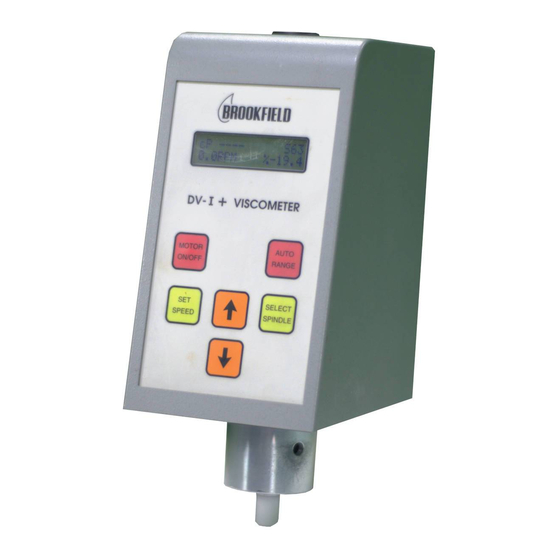
BROOKFIELD DIGITAL VISCOMETER
MODEL DV-I
Operating Instructions
Manual No. M/92-021-N0902
Model No.
Serial No.
BROOKFIELD ENGINEERING LABORATORIES, INC.
11 Commerce Boulevard, Middleboro, MA 02346-1031 USA
T
800-628-8139 or 508-946-6200
EL
www.brookfieldengineering.com
+
SPECIALISTS IN THE
MEASUREMENT AND
CONTROL OF VISCOSITY
F
508-946-6262
AX
Page 1
Manual No. M/92-021-N0902
Advertisement
Table of Contents

Related Manuals for Brookfield DV-I+ Series


Summary of Contents for Brookfield DV-I+ Series
- Page 1 Model No. Serial No. SPECIALISTS IN THE MEASUREMENT AND CONTROL OF VISCOSITY BROOKFIELD ENGINEERING LABORATORIES, INC. 11 Commerce Boulevard, Middleboro, MA 02346-1031 USA 800-628-8139 or 508-946-6200 508-946-6262 www.brookfieldengineering.com Brookfield Engineering Laboratories, Inc.
-
Page 3: Table Of Contents
Appendix I - DVE-50 Probe Clip ....................45 Appendix J - Fault Diagnosis and Troubleshooting ..............46 Appendix K - Warranty Repair and Service ................. 48 Appendix L - Viscosity Test Report ..................... 51 Brookfield Engineering Laboratories, Inc. Page 2 Manual No. M/92-021-N0902... -
Page 4: Introduction
INTRODUCTION The Brookfield DV-I+ Viscometer measures fluid viscosity at given shear rates. Viscosity is a measure of a fluid’s resistance to flow. You will find a detailed description of the mathematics of viscosity in the Brookfield publication “More Solutions to Sticky Problems” a copy of which was included with your DV-I+. -
Page 5: Components
DVE-50 Please check to be sure that you have received all components and that there is no damage. If you are missing any parts, please notify Brookfield Engineering or your local Brookfield agent immediately. Any shipping damage must be reported to the carrier. -
Page 6: Specifications
(spanner). Attach leveling feet. Insert the mounting rod on the back of the DV-I+ Viscometer into the hole on the clamp assembly. Be sure that the clamp screw, VS-41Y, is loose. Brookfield Engineering Laboratories, Inc. Page 5 Manual No. M/92-021-N0902... -
Page 7: Safety Symbols And Precautions
The user should ensure that the substances placed under test do not release poisonous, toxic or flammable gases at the temperatures to which they are subjected to during the testing. Brookfield Engineering Laboratories, Inc. Page 6 Manual No. M/92-021-N0902... -
Page 8: Key Functions
Initiates spindle selection on the first press and then selects the currently scrolled-to spindle when pressed a second time. Used for Time to Torque and Timed Stop tests. (See Section II.9 - Timed Modes for Viscosity Measurement.) Brookfield Engineering Laboratories, Inc. Page 7 Manual No. M/92-021-N0902... -
Page 9: Cleaning
Spindles are made of stainless steel. Clean with non-abra- sive cloth and solvent appropriate for sample material that is not aggressive to immersed components. When cleaning, do not apply excessive force which may result in bending spindles. Brookfield Engineering Laboratories, Inc. Page 8 Manual No. M/92-021-N0902... -
Page 10: Getting Started
After approximately 15 seconds, the flashing stops and the following screen appears: REPLACE SPINDLE PRESS ANY KEY Figure II-4 Pressing any key at this point results in the display of the DV-I+ default screen: Brookfield Engineering Laboratories, Inc. Page 9 Manual No. M/92-021-N0902... -
Page 11: Ii.2 Spindle Selection
S S S S S Press the key once again. This will cause the character to cease blinking and SELECT SPINDLE the new spindle code will be accepted for use in viscometer calculations. Brookfield Engineering Laboratories, Inc. Page 10 Manual No. M/92-021-N0902... - Page 12 % 0.0 Figure II-7 The DV-I+ may also be programmed at Brookfield Engineering for “special” user spindles. These “special” spindles will show up on the spindle scroll list starting with the designation "AA" and continuing through "AZ". Contact Brookfield Engineering regarding your needs for special spindles.
-
Page 13: Ii.3 Speed Selection & Setting
The DV-I+ may also be programmed with “special” speed sets. A list of special speed sets is included in Appendix F. Please consult Brookfield Engineering or your local dealer/distributor for any special speed requirements not addressed by the standard or special speed sets. -
Page 14: Ii.4 Autorange
1. Turn the power off. 2. Press and hold the key and turn the power ON. AUTO RANGE The DV-I+ will retain the unit selection when the viscometer is turned OFF. Brookfield Engineering Laboratories, Inc. Page 13 Manual No. M/92-021-N0902... -
Page 15: Ii.6 Temperature Display In °F Or °C Selection
. s Viscosity DV-I+ Viscometers without this function can be updated. Contact Brookfield or your local Brookfield dealer for this service. ° ° II.6 Temperature Display in F or C Selection Pressing and holding the key during power on will enable the temperature display DOWN ARROW to be read in either degrees Fahrenheit or degrees Centigrade. -
Page 16: Ii.8 Operation
Viscometer is running and the characteristics of the sample fluid. For maximum accuracy, readings below 10% should be avoided. Additional information on making viscosity measurements is available in Appendix C or the Brookfield publication “More Solutions to Sticky Problems”. - Page 17 The user presses the key one more time at which point the viscometer will SELECT SPINDLE display the following screen: TIMED STOP:PRESS MOTOR ON OFF Figure II-18 Brookfield Engineering Laboratories, Inc. Page 16 Manual No. M/92-021-N0902...
- Page 18 II.9.3 Time to Torque 1. After pressing the key when in the display of Figure II-15, the user is DOWN ARROW presented with the following screen: Brookfield Engineering Laboratories, Inc. Page 17 Manual No. M/92-021-N0902...
- Page 19 At this point, the viscometer will stop the motor and continue to display this screen until the user presses the keys to view the viscosity that was current at the DOWN ARROW Timed Torque completion. The display would appear as follows: Brookfield Engineering Laboratories, Inc. Page 18 Manual No. M/92-021-N0902...
- Page 20 NOTE: For the Time to Torque method, the DV-I+ Viscometer will retain the last entered torque in EEPROM for use when the user elects to perform a time to torque test again. Brookfield Engineering Laboratories, Inc. Page 19 Manual No. M/92-021-N0902...
-
Page 21: Appendix A - Cone/Plate Viscometer Set-Up
DV-I+ Cone/Plate Viscometers, S/N 50969 and higher, have an Electronic Gap Setting feature. This feature enables the user to easily find the 0.0005 inch gap setting that was established at Brookfield prior to shipment. The following information explains how to set the Electronic Gap and verify calibration of the DV-I+ Viscometer. - Page 22 Electronic Gap Setting feature “on”. Be sure Do Not hit the to shut the feature “off” before taking readings! CONE with the CUP! Figure A-4 Brookfield Engineering Laboratories, Inc. Page 21 Manual No. M/92-021-N0902...
- Page 23 1. The cup may be removed and replaced without resetting the gap if the micrometer adjustment ring has not been moved. 2. Remove the spindle from the viscometer when cleaning. 3. Re-establish the hit point every time the spindle is attached/detached. Brookfield Engineering Laboratories, Inc. Page 22 Manual No. M/92-021-N0902...
- Page 24 5000 cP sample, cup and cone to reach tem- with a Cone/Plate. Brookfield offers a com- perature equilibrium. plete range of mineral oil viscosity standards suitable for use with Cone/Plates for viscosi- 5.
-
Page 25: Appendix B - Viscosity Ranges
214000 - 2140000 Notes: 1) 1 Pa = 10 dyne/cm 2) 1 cP = 1 mPa•s 3) Possibility of turbulence at speeds above 10 rpm may give artificially higher viscosity readings. Brookfield Engineering Laboratories, Inc. Page 24 Manual No. M/92-021-N0902... - Page 26 5,000 98 - 5,000 1.22N 4 - 3,800 37 - 10,000 73 - 10,000 292 - 10,000 1.29N 11 - 38,000 121 - 50,000 243 - 50,000 970 - 50,000 1.29N Brookfield Engineering Laboratories, Inc. Page 25 Manual No. M/92-021-N0902...
- Page 27 The second consideration involves the mechanics of fluid flow. All rheological measurements of fluid flow properties should be made under laminar flow conditions. Laminar flow is flow wherein Brookfield Engineering Laboratories, Inc. Page 26 Manual No. M/92-021-N0902...
- Page 28 2) No. 1 RV Spindle: 100 cP at 50 RPM 3) UL Adapter: 0.85 cP at 60 RPM Turbulent conditions will exist in these situations whenever the RPM/cP ratio exceeds the values listed above. Brookfield Engineering Laboratories, Inc. Page 27 Manual No. M/92-021-N0902...
-
Page 29: Appendix C - Variables In Viscosity Measurement
If you set a viscometer at a constant speed recording viscosity values over time and find that the viscosity values decrease with time, the material is thixotropic. Brookfield publication, “More Solutions to Sticky Problems”, includes a more detailed discus- sion of rheological properties and non-Newtonian behavior. Brookfield Engineering Laboratories, Inc. - Page 30 5) Spindle used (if using LVDV-I+ (#1-4) or RVDV-I+ (#1-7) attach the guard leg) 6) Test speed or speeds (or the shear rate) 7) Length of time or number of spindle revolutions to record viscosity. Brookfield Engineering Laboratories, Inc. Page 29 Manual No. M/92-021-N0902...
-
Page 31: Appendix D - Spindle And Model Codes
SC4-16 SC4-18 SC4-21 SC4-25 SC4-27 SC4-28 SC4-29 SC4-31 SC4-34 SC4-37 CPE40 0.327 CPE41 1.228 CPE42 0.64 CPE51 5.178 CPE52 9.922 1280 V-71 2.62 SPIRAL V-72 11.10 V-73 53.50 1000 Table D-1 Brookfield Engineering Laboratories, Inc. Page 30 Manual No. M/92-021-N0902... - Page 32 Table D-2 lists the model codes and spring torque constants for each viscometer model. VISCOMETER TORQUE CONSTANT MODEL CODE MODEL ON DV-I+ SCREEN LVDV-I+ 0.09373 2.5xLVDV-I+ 0.2343 5xLVDV-I+ 0.4686 1/4 RVDV-I+ 0.25 1/2 RVDV-I+ RVDV-I+ HADV-I+ 2xHADV-I+ 2.5xHADV-I+ HBDV-I+ 2xHBDV-I+ 2.5xHBDV-I+ 5xHBDV-I+ Table D-2 Brookfield Engineering Laboratories, Inc. Page 31 Manual No. M/92-021-N0902...
-
Page 33: Appendix E - Calibration Procedures
Appendix E - Calibration Procedures The accuracy of the DV-I+ is verified using viscosity standard fluids which are available from Brookfield Engineering Laboratories or your local Brookfield agent. Viscosity standards are Newtonian, and therefore, have the same viscosity regardless of spindle speed (or shear rate). Viscosity standards, °... - Page 34 Brookfield Viscosity Standard Fluid - General Information We recommend that Brookfield Viscosity Standard Fluids be replaced on an annual basis, one year from date of initial use. These fluids are either pure silicone or mineral oil and are not subject to change over time.
- Page 35 A two-step process is recommended for the Thermosel. 1) Evaluate the calibration of the Viscometer alone according to the procedure outlined in this section, entitled Calibration Procedure for LV (#1-4) and RV,HA,HB (#1-7) Brookfield spindles. 2) Evaluate the Viscometer with the Thermosel according to the procedure decribed below.
- Page 36 6) Measure the viscosity and record the viscometer reading; include % and cP (m•Pas). NOTE: The spindle must rotate at least five (5) times before a viscosity reading is taken. Brookfield Engineering Laboratories, Inc. Page 35 Manual No. M/92-021-N0902...
- Page 37 5000 cP with a Cone/ Plate Viscometer. Brookfield offers a complete range of mineral oil viscosity standards suitable for use with Cone/Plate Viscometers. See Table E-2. It is best to use a viscosity standard fluid that will be close to the maximum viscosity for a given cone spindle/speed combination.
- Page 38 The guard leg was originally designed to protect the spindle during use. The first applications of the Brookfield Viscometer included hand held operation while measuring fluids in a 55 gallon drum. It is clear that under those conditions the potential for damage to the spindle was great. Original construc- tion included a sleeve that protected the spindle from side impact.
- Page 39 Brookfield factor if the boundary conditions are not those specified by Brookfield. The guard leg is a part of the calibration check of the Brookfield LV and RV series Viscometer/Rheom- eter. Our customers should be aware of its existence, its purpose and the effect that it may have on data.
-
Page 40: Appendix F - Special Speed Sets
Appendix F - Special Speed Sets The following special speeds sets are available from Brookfield Engineering Laboratories. All speeds are in units of RPM. SPEED SET (RPM) Step SS200 SS150 SS100 SS50 SS25 SSINT Table F-1 Please consult Brookfield Engineering or your local dealer/distributor for any special speed requirements not addressed by either the standard speed sets shown in Table 1 (page 8) or in Table F-1. -
Page 41: Appendix G - Communications
(Not used with DV-I White Wire: % Torque Output Green Wire: % Torque Ground Please contact Brookfield Engineering Laboratories or your local dealer/distributor for purchase of the DVP-96Y analog output cable. Brookfield Engineering Laboratories, Inc. Page 40 Manual No. M/92-021-N0902... -
Page 42: Appendix H - Laboratory Stand With Parts Identification
GEAR SCREW ASSEMBLY VS-41Y CLAMP SCREW ASSEMBLY VS-29 TENSION INSERT VS-29W BELLEVILLE SPRING WASHER VS-28 TENSION SCREW Figure H-1 *Provided with instruments shipped after October 1, 1999. Replaced Model A Laboratory Stand. Brookfield Engineering Laboratories, Inc. Page 41 Manual No. M/92-021-N0902... - Page 43 Center the Viscometer relative to the stand base and retighten the large slotted pan head screw as required. Referring to the Viscometer bubble level, adjust the leveling screws until the instru- ment is level. Brookfield Engineering Laboratories, Inc. Page 42 Manual No. M/92-021-N0902...
- Page 44 SCREW, 4-40 X 3/8 LG. SOC. HD. CAP, 18-8 SS BLM-4E ROD EXTENSION-4" LONG OPTIONAL BLM-4E2 RODE EXTENSION - 8" LONG OPTIONAL Figure H-2 **Provided with instruments shipped before October 1, 1999 Brookfield Engineering Laboratories, Inc. Page 43 Manual No. M/92-021-N0902...
- Page 45 Center the Viscometer relative to the stand base and retighten the jam nut as required. Referring to the Viscometer bubble level, adjust the leveling screws until the instrument is level. Operation Rotate the Gear Screw to raise or lower the viscometer. Brookfield Engineering Laboratories, Inc. Page 44 Manual No. M/92-021-N0902...
-
Page 46: Appendix I - Dve-50 Probe Clip
LV Guard Leg RTD Temperature Assembly, B-20Y Probe DVE-50 Probe Clip DVE-50 RTD Temperature Probe Clip Probe No. 14000 600 ml Low Form Griffin Beaker Figure I-2 Figure I-3 Brookfield Engineering Laboratories, Inc. Page 45 Manual No. M/92-021-N0902... -
Page 47: Appendix J - Fault Diagnosis And Troubleshooting
Watch the coupling screw swing freely and rest on zero; watch the % values decrease and rest at 0.0 (±0.1%) If the viscometer does not rest at zero, the unit is need of service. See Appendix G for details on how to return your viscometer. Brookfield Engineering Laboratories, Inc. Page 46 Manual No. M/92-021-N0902... - Page 48 • Verify calibration check procedures were followed exactly. If the unit is found to be out of tolerance, the unit may be in need of service. See Appendix G for details on how to return your viscometer. Brookfield Engineering Laboratories, Inc. Page 47 Manual No. M/92-021-N0902...
-
Page 49: Appendix K - Warranty Repair And Service
Institute of Standards and Technology (NIST). The Viscometer must be returned to Brookfield Engi- neering Laboratories, Inc. or the Brookfield dealer from whom it was purchased for no charge war- ranty service. Transportation is at the purchaser's expense. The Viscometer should be shipped in its carrying case together with all spindles originally provided with the instrument. - Page 50 If available, use the original foam insert or roll up one sheet of tissue paper (or similar) and place between the spindle coupling and cup assembly (see Figure K2). This will help prevent damage in shipping. Brookfield Engineering Laboratories, Inc. Page 49 Manual No. M/92-021-N0902...
- Page 51 Please fill out and return a copy of this form with your instrument. Brookfield recommends that all viscometers be returned for annual calibration to ensure that your equipment continues to provide the same accuracy you have come to expect from Brookfield products. VISCOMETER INFORMATION...
-
Page 52: Appendix L - Viscosity Test Report
TEST INFORMATION: DIAL READING VISCOSITY SHEAR TEMP SAMPLE MODEL SPINDLE FACTOR TIME NOTES °C % TORQUE RATE CONCLUSIONS: BROOKFIELD ENGINEERING LABORATORIES, INC. • 11 Commerce Boulevard • Middleboro, MA 02346 • TEL: 508-946-6200 or 800-628-8139 (USA) FAX: 508-946-6262 • www.brookfieldengineering.com...
Need help?
Do you have a question about the DV-I+ Series and is the answer not in the manual?
Questions and answers