Table of Contents
Advertisement
Brookfield Engineering Labs., Inc.
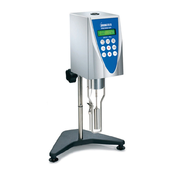
BROOKFIELD DV-II+Pro
Viscometer
Operating Instructions
Manual No. M/03-165 D0410
Boston • Chicago • London • Stuttgart • Guangzhou
with offices in :
BROOKFIELD ENGINEERING LABORATORIES, INC.
11 Commerce Boulevard, M iddleboro, M A 02346 USA
T
508-946-6200
or
EL
F
508-946-6262
I
AX
NTERNET
SPECIALISTS IN THE
MEASUREMENT AND
CONTROL OF VISCOSITY
800-628-8139 (USA e xcluding MA)
http://www .brookfieldengineering.com
Page
Manual No. M/03-65-D040
Advertisement
Table of Contents


Need help?
Do you have a question about the RVDV-II+Pro and is the answer not in the manual?
Questions and answers