Table of Contents
Advertisement
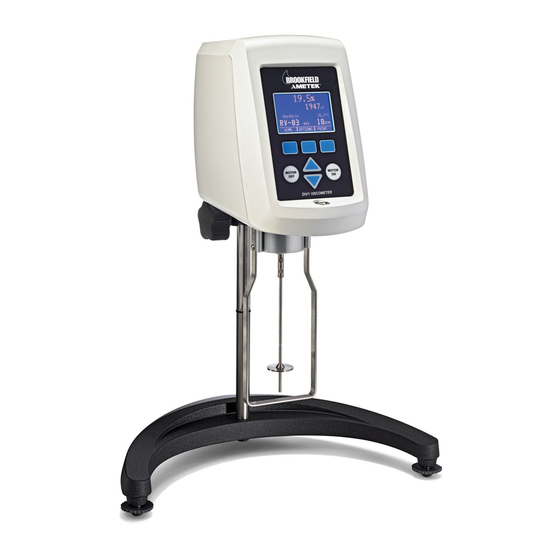
BROOKFIELD DV1
Digital Viscometer
Operating Instructions
Manual No. M14-023
Boston • Chicago • London • Stuttgart • Guangzhou
with offices in:
BROOKFIELD ENGINEERING LABORATORIES, INC.
11 Commerce Boulevard, Middleboro, MA 02346 USA
T
508-946-6200
or
800-628-8139 (USA excluding MA)
EL
F
508-946-6262
I
http://www .brookfieldengineering.com
AX
NTERNET
SPECIALISTS IN THE
MEASUREMENT AND
CONTROL OF VISCOSITY
Advertisement
Table of Contents

Related Manuals for Brookfield DV1


Summary of Contents for Brookfield DV1
- Page 1 Manual No. M14-023 SPECIALISTS IN THE MEASUREMENT AND CONTROL OF VISCOSITY Boston • Chicago • London • Stuttgart • Guangzhou with offices in: BROOKFIELD ENGINEERING LABORATORIES, INC. 11 Commerce Boulevard, Middleboro, MA 02346 USA 508-946-6200 800-628-8139 (USA excluding MA) 508-946-6262 http://www .brookfieldengineering.com...
-
Page 3: Table Of Contents
TABLE OF CONTENTS I. INTRODUCTION ......................5 I.1 Components ........................6 I.2 Utilities ..........................7 I.3 Components and Dimensions ..................... 8 I.4 Specifications ........................10 I.5 Installation ........................11 I.6 Safety Symbols and Precautions ..................11 I.7 Key Functions........................12 I.8 Preventative Maintenance and Cleaning ................13 II. GETTING STARTED ....................14 II.1 Power Up ......................... - Page 4 Appendix B - Viscosity Ranges ..................36 Appendix C - Variables in Viscosity Measurements ............ 40 Appendix D - Spindle Entry Codes and SMC/SRC Values ..........42 Appendix E - Spindle Entry Codes and Range Coefficients .......... 45 Appendix F - Calibration Check Procedures ..............47 Appendix G - The Brookfield Guardleg................ 54 Appendix H - Laboratory Stands with Parts Identification .......... 56 Appendix I - DVE-50A Probe Clip ................. 58 Appendix J - Fault Diagnosis and Troubleshooting ............59 Appendix K - Online Help and Additional Resources ..........59 Appendix L - Warranty Repair and Services ..............60 Viscosity Test Report ..................
-
Page 5: Introduction
Solutions to Sticky Problems”, a copy of which was included with your DV1. The principle of operation of the DV1 is to drive a spindle (which is immersed in the test fluid) through a calibrated spring. The viscous drag of the fluid against the spindle is measured by the spring deflection. -
Page 6: Components
Viscosity: 1 mPa•s 1 cP Torque: 1 Newton•m dyne•cm References to viscosity throughout this manual are done in CGS units. The DV1 Viscometer provides equivalent information in SI units. I.1 Components COMPONENT PART NUMBER QUANTITY varies Model G Laboratory Stand... -
Page 7: Utilities
50/60 Hz Power Consumption: 50 VA Power Cord Color Code: Outside United States United States United States Outside United States Hot (live) Black Brown Neutral White Blue Ground (earth) Green Green/Yellow Brookfield Engineering Laboratories, Inc. Page 7 Manual No. M14-023... -
Page 8: Components And Dimensions
Cone/Plate Option Temperature Probe Option • For use with SSA or C/P: Wrench Temperature Cable SC4-61Y • For use in beaker: Temperature Probe Clip Cone Spindle Sample Cup Temperature Probe Figure I-1 Brookfield Engineering Laboratories, Inc. Page 8 Manual No. M14-023... - Page 9 14 7/8 [37.8 cm] B-21Y RV GUARD LEG 16 13/32 ASSEMBLY [41.7 cm] 7 3/8 [18.7 cm] 3 3/16 [8.1 cm] GV-1201 13 7/8 [35.2 cm] LAB STAND BASE ASSEMBLY Figure I-2 Brookfield Engineering Laboratories, Inc. Page 9 Manual No. M14-023...
-
Page 10: Specifications
Users within the European Union: Please contact your dealer or the local authorities in charge of waste management on how to dispose of this product properly. All Brookfield offices and our network of representatives and dealers can be found on our website: www.brookfieldengineering.com Users outside of the European Union: Please dispose of this product according to your local laws. -
Page 11: Installation
Refer to Figure I-2 for the following, except where noted. 7) Make sure that the AC power switch at the rear of the DV1 is in the OFF position. Connect the power cord to the socket on the back panel of the instrument and plug it into the appropriate AC line. -
Page 12: Key Functions
On/O Switch Figure I-2 I.7 Key Functions Figure I-3 shows the control keys on the face of the DV1 Viscometer. The following describes each key’s function. HOT KEY Three Hot Keys are located immediately below the display. The action executed by the hot key will be indicated on the display. -
Page 13: Preventative Maintenance And Cleaning
When cleaning spindles, do not apply excessive force, which may result in bending the spindle shaft. Brookfield Engineering Laboratories, Inc. Page 13 Manual No. M14-023... -
Page 14: Getting Started
II. GETTING STARTED II.1 Power Up The DV1 Viscometer will go through a Power Up sequence when the power is turned on. The viscometer will present a blue screen for approximately 4 seconds and then the About Screen for 5 seconds. The About Screen is shown below and includes several critical parameters about the viscometer including: viscometer torque (LV, RV, HA, HB, or other), and the firmware version number. -
Page 15: Ii.3 Navigation
See Section I.7 for a description of Key Functions. Hot Keys are used on the DV1 Viscometer to assist with menu navigation. There are three Hot Keys located immediately under the viscometer display. The function of each key is indicated at the bottom of the display and may change depending on the screen currently in view. - Page 16 The motor should be OFF whenever spindles are being removed or attached. NOTE: Keep the EZ-Lock Spindle Coupling and outer sleeve as clean as possible and free from debris that could become lodged inside the adapter. Brookfield Engineering Laboratories, Inc. Page 16 Manual No. M14-023...
- Page 17 The DV1 requires a Spindle Entry Code number to calculate viscosity values. The two-digit code for each spindle can be found in Appendix D. Pressing the SPINDLE Hot Key on the Home screen will present the Set Spindle screen. Figure II-5 Press the Up/Down Arrow keys to scroll through the list of available spindles.
-
Page 18: Ii.6 Speed Selection
Beginning Table II-1 NOTE: DV1 speeds are organized to conform to the historical speed sets available on the Brookfield Dial Reading viscometer. Speeds from 0.3-60 RPM are traditionally found on the LVT viscometer. Speeds from 0.5-100 RPM are traditionally found on RVT, HAT and HBT viscometers. -
Page 19: Ii.7 Full Scale Range
The Full Scale Range (FSR) is a calculation of the maximum viscosity value that can be measured by a spindle and speed combination when used with the specific spring torque of the DV1 Viscometer. This value represents the measured viscosity which will be displayed when the instrument’s %torque reading is at 100. -
Page 20: Ii.8 Options
The end condition currently in use on the DV1 can be identified by choosing RUN UNTIL in the Options Menu. The end condition will be displayed on the screen along with the parameter value. -
Page 21: Ii.8.2 Test View
Temperature for the Run Until Temp. end condition. For example, if the temperature probe is placed in a water bath that is set to rise to 50°C, the DV1 Viscometer may display 49.5°C when the temperature bath is at thermal equilibrium. Since the accuracy of temperature measurement is +/-1°C, this result is considered correct. -
Page 22: Ii.8.3 Visc Units
UNITS screen in the Options Menu displays the currently set temperature units. The factory setting is C. To change the TEMP UNITS value, press the SELECT Hot Key and then use the Arrow Keys Brookfield Engineering Laboratories, Inc. Page 22... -
Page 23: Ii.8.5 Tmp. Offset
1.0°C in the range of -100° to 149.9°C and +/-2.0°C in the range of 150° to 300°C. An offset may be entered into the DV1 to adjust the temperature reading to be in agreement with a third party measurement device. The offset can be set to any value between -5.0° to 5.0°C or -9.0° to 9.0°F. -
Page 24: Ii.8.10 Service
Service Menu. II.9 Printing The DV1 Viscometer is configured to print to the DYMO Label Writer 450 Turbo label printer. This printer can be purchased from Brookfield (Part No. GV-1046). No other printer is supported. The DV1 offers one printing format which is compatible with the Shipping Label (GV-1049-10, 2.31 inch x 4.00 inch) and the Address Label (GV-1048-10, 1.13 inch x 3.50 inch). - Page 25 • Actual Time of Test • Test Mode (Run Until) • Test Mode Parameter (Manual indicates no time given) • Spindle represented by both name and number • Torque range of the DV1 (HB) • Speed • Measured Viscosity • Measured Temperature • Measured Torque...
-
Page 26: Making Viscosity Measurements
Dial Reading Viscometer and the DV series of Digital Viscometers. If you have experience with other Brookfield equipment, this section will give you the quick steps for taking a viscosity reading. If you have not used a Brookfield Viscometer before, skip this section and go to Section III.2 for a detailed description. -
Page 27: Iii.3 Selecting A Spindle/Speed
II.2). Live measurement data will be displayed during the test. When the end criteria is met, the final data will be displayed on the DV1 until the user presses a key. The following procedure outlines the general steps necessary for making a viscosity measurement in a 600mL low form Griffin beaker using the standard LV/RV/HA/HB spindles (61-64, 2-7). -
Page 28: Iii.5 Communication With Wingather Sq Software
% Torque and viscosity. Relevant test parameters might include: viscometer model, spindle, speed, temperature, container size and time of test. A label printer can be used with the DV1. See the sample Viscosity Test Report at the end of the Appendices. - Page 29 Figure III-1 TIP: If communication cannot be established between the DV1 and Wingather SQ, select the CONNECT function within the DV1 Options menu (see Section II.8.7). Important features and benefits in Wingather SQ, which enhance operator versatility in performing a viscosity test, include: • Multiple Test Modes to enhance data collection...
- Page 30 Figure III-4: Data Table and Graph Figure III-5: Help Menu Brookfield Engineering Laboratories, Inc. Page 30 Manual No. M14-023...
-
Page 31: Appendix A - Cone/Plate Viscometer Set-Up
5 times the gap setting. A more conservative approach is to limit the maximum particle size to less than 10 times the gap setting. The following information explains how to set the Electronic Gap and verify calibration of the DV1 Viscometer. - Page 32 The temperature range of the CPE-44PY) Sample Cup (CPE-44Y or CPE-44PY) is 0°- Figure A-2 100°C. Brookfield recommends a maximum temperature of 80°C to allow for direct hand contact for adjustment of the micrometer ring. When using the sample cup at temperatures near 0°C, be careful to avoid frost buildup on...
- Page 33 The cup may be removed and replaced without resetting the gap, if the micrometer adjustment ring has not been moved. Remove the spindle from the viscometer when cleaning. Re-establish the hit point every time the spindle is attached/detached. Brookfield Engineering Laboratories, Inc. Page 33 Manual No. M14-023...
- Page 34 A.4 Making Measurements with Cone/Plate Geometry Viscosity measurements are made on the DV1 C/P viscometer in the same way as the DV1 viscometer with several exceptions. Prepare the viscometer as is described in Section III.2. Brookfield recommends that you always make cone/plate measurements with temperature control.
- Page 35 Determine the appropriate sample volume. Refer to Table A-1 to determine the correct sample volume required for the spindle to be utilized. Select a Brookfield Viscosity Standard fluid that will give viscosity readings between 10% and 100% of Full Scale Range. Refer to Appendix B for viscosity ranges of cone spindles; ranges listed apply to CPA cones.
-
Page 36: Appendix B - Viscosity Ranges
434400 - 4344000 V-75 320-3200 3200-32000 170400 - 1704000 Notes: 1) 1 Pa = 10 dyne/cm 2) 1 cP = 1 mPa•s 3) Possibility of turbulence at speeds above 10 RPM may give artificially higher viscosity readings. Brookfield Engineering Laboratories, Inc. Page 36 Manual No. M14-023... - Page 37 DV1MHB YULA-15 or 15Z 1 - 2,000 7 - 2,000 13 - 2,000 52 - 2,000 1.22N ULA-DIN-Y 1 - 3,800 11 - 5,000 22 - 5,000 85 - 2000 1.29N Brookfield Engineering Laboratories, Inc. Page 37 Manual No. M14-023...
- Page 38 4,000,000 40,000 - 8,000,000 160,000 - 32,000,000 3,900 - 1,560,000 50,000 - 10,000,000 100,000 - 20,000,000 400,000 - 80,000,000 7,800 - 3,120,000 100,000 - 20,000,000 200,000 - 40,000,000 800,000 - 160,000,000 Brookfield Engineering Laboratories, Inc. Page 38 Manual No. M14-023...
- Page 39 Viscosity measurements should be taken under laminar flow conditions, not under turbulent flow conditions. The first consideration has to do with the accuracy of the instrument. All DV1 Viscometers have a Full Scale Range allowable error of (+/-) 1% of any spindle/speed in use. We discourage taking readings below 10% of range because the potential viscosity error of (+/-) 1% is a relatively high number compared to the instrument reading.
-
Page 40: Appendix C - Variables In Viscosity Measurements
If you set a viscometer at a constant speed recording viscosity values over Thixotropic time and find that the viscosity values decrease with time, the material is thixotropic. Brookfield publication, “More Solutions to Sticky Problems”, includes a more detailed discussion of rheological properties and non-Newtonian behavior. Brookfield Engineering Laboratories, Inc. Page 40... - Page 41 5) Spindle used numbered 6) Test speed or speeds (or the shear rate) 7) Length of time or number of spindle revolutions to record viscosity 8) Presence/absence of guard leg (LV or RV models) Brookfield Engineering Laboratories, Inc. Page 41 Manual No. M14-023...
-
Page 42: Appendix D - Spindle Entry Codes And Smc/Src Values
When using a standard Brookfield digital Viscometer or Rheometer, each spindle has a two digit entry code which is entered via the keypad on the DV1. The entry code allows the DV1 to calculate Viscosity, Shear Rate and Shear Stress values and can also be calculated when using coaxial cylinder geometry (SSA, ULA, Thermosel, DAA, etc.) and cone/plate geometry. - Page 43 CP-52 / CPE-52 / CPA-52Z 9.922 V-71 2.62 V-72 11.1 V-73 53.5 V-74 V-75 Table D-1 (Continued from previous page) Table D-2 lists the model codes and spring torque constants for each viscometer model. Brookfield Engineering Laboratories, Inc. Page 43 Manual No. M14-023...
- Page 44 2.5xDV1HB 2.5HB Table D-2 The full scale viscosity range for any DV1 model and spindle may be calculated using the equation: Full Scale Viscosity Range [cP] = TK * SMC * 10,000 where: = DV1 Torque Constant from Table D-2...
-
Page 45: Appendix E - Spindle Entry Codes And Range Coefficients
4,000,000 8,000,000 32,000,000 6,000 64,000 128,000 512,000 320,000 640,000 2,560,000 30,000 1,280,000 2,560,000 10,240,000 120,000 LV4 or 4B2 600,000 6,400,000 12,800,000 51,200,000 12,800,000 25,600,000 102,400,000 1,200,000 LV-2C 320,000 640,000 2,560,000 30,000 Brookfield Engineering Laboratories, Inc. Page 45 Manual No. M14-023... - Page 46 V-71 2,456 26,200 52,400 209,600 V-72 111,000 222,000 888,000 10,404 V-73 535,000 1,070,000 4,280,000 50,146 V-74 508,954 5,430,000 10,860,000 43,440,000 V-75 2,130,000 4,260,000 8,520,000 199,645 Table E-1 (Continued on previous page) Brookfield Engineering Laboratories, Inc. Page 46 Manual No. M14-023...
-
Page 47: Appendix F - Calibration Check Procedures
• DIN Adapter • Spiral Adapter The accuracy of the DV1 is verified using viscosity standard fluids, which are available from Brookfield Engineering Laboratories or your local Brookfield agent. Viscosity standards are Newtonian, and there- fore, have the same viscosity regardless of spindle speed (or shear rate). Viscosity standards, calibrated at 25°C, are shown in Table F-1 (Silicone Oils) and Table F-2 (Mineral Oils). - Page 48 Brookfield Viscosity Standard Fluid - General Information We recommend that Brookfield Viscosity Standard Fluids be replaced on an annual basis, one year from date of initial use. These fluids are either pure silicone or mineral oil and are not subject to change over time.
- Page 49 Follow theses steps using one of the recommended spindles to verify calibration of your instrument. 1) Place the viscosity standard fluid (in the proper container) into the water bath. 2) Lower the DV1 into measurement position (with guard leg if LV or RV series viscometer is used).
- Page 50 5) Put the spindle into the test fluid and attach the extension link, coupling nut and free hanging spindle (or directly attach the solid shaft spindle) to the DV1. 6) Allow sufficient time for the viscosity standard, sample chamber and spindle to reach test temperature.
- Page 51 1) Place the viscosity standard fluid (in the proper container) into the water bath. 2) Attach the spindle to the viscometer. Attach chamber (SA-1Y) and clamp to the viscometer. 3) Lower the DV1 into measurement position. Operate the viscometer at 50 or 60 RPM until the chamber is fully flooded.
- Page 52 NOTE: The spindle must rotate at least five (5) times before readings are taken. Interpretation of Calibration Test Results: When verifying the calibration of the DV1, the instrument and viscosity standard fluid error must be combined to calculate the total allowable error.
- Page 53 Any reading outside these limits may indicate a viscometer problem. Contact the Brookfield technical sales department or your local authorized Brookfield dealer with test results to determine the nature of the problem. Calculate the acceptable range of viscosity using DV1MRV with Small Sample adapter at 10 RPM;...
-
Page 54: Appendix G - The Brookfield Guardleg
The current guard leg is a band of metal in the shape of the letter U with a bracket at the top that attaches to the pivot cup of a Brookfield Viscometer/Rheometer. Because it must attach to the pivot cup, the guard leg cannot be used with a Cone/Plate instrument. - Page 55 The guard leg is a part of the calibration check of the Brookfield LV and RV series Viscometer/Rheometer. Our customers should be aware of its existence, its purpose and the effect that it may have on data. With this knowledge, the viscometer user may make modifications to the recommended method of operation to suit their needs.
-
Page 56: Appendix H - Laboratory Stands With Parts Identification
Base, Models G and QB (includes 2 VS-3 leveling screws) 502028071S33B Flat washer 5/16 x 7/8 x .071” 50S311832S01B Screw, 5/16-18 x 1" lg. hex head GV-1203 Leveling Screws, Model G and QB Figure H-1 Brookfield Engineering Laboratories, Inc. Page 56 Manual No. M14-023... - Page 57 If the slot is not in the correct position, the clamp will not slide down over the upright rod. Use a small screwdriver or pencil to move it into the correct position. Brookfield Engineering Laboratories, Inc. Page 57...
-
Page 58: Appendix I - Dve-50A Probe Clip
Appendix I - DVE-50A Probe Clip Probe Clip DVE-50A is supplied with the DV1 Optional Temperature Probe. It is used to attach the RTD temperature probe to the LV/RV Guard Leg or 600mL low form Griffin beaker. Figure I-1 is a view of the Probe Clip, showing the hole into which the RTD probe is inserted, and the slot which fits onto the LV/RV guard leg. -
Page 59: Appendix J - Fault Diagnosis And Troubleshooting
Verify that calibration check procedures were followed exactly. If the unit is found to be out of tolerance, the unit may be in need of service. See Appendix L for details on how to return your viscometer. Brookfield Engineering Laboratories, Inc. Page 59 Manual No. M14-023... -
Page 60: Appendix K - Online Help And Additional Resources
Brookfield is involved with a satellite website that should be your first stop in viscosity research. This site serves as a library of interviews with experts in the viscosity field as well as Brookfield technical articles and conversion charts. Registration is required so that you can be notified of upcoming interviews and events, however, this information will not be shared with other vendors, institutions, etc. -
Page 61: Appendix L - Warranty Repair And Services
If returning to Brookfield, please contact us for a return authorization number prior to shipping. Failure to do so will result in a longer repair time. -
Page 63: Viscosity Test Report
Viscosity Test Report...
Need help?
Do you have a question about the DV1 and is the answer not in the manual?
Questions and answers