Table of Contents
Advertisement
Advertisement
Table of Contents

Subscribe to Our Youtube Channel
Related Manuals for Brookfield RST


Summary of Contents for Brookfield RST
- Page 1 Operating Instructions for the RST Rheometer...
- Page 2 >%'(P1($//"* + ++++++++++++++++++++++++++++++++++++++++++++++++++++++++++++++++++++++++++++++++++++++++++++++++++++++++++++++++++++++++*AH !!!+, >P/*./"'*781#/9*%;*#P/*F7>*FP/%9/#/$* + +++++++++++++++++++++++++++++++++++++++++++++++++++++++++++++++++++++++++++++*AH !!!+< C&)#*++++++++++++++++++++++++++++++++++++++++++++++++++++++++++++++++++++++++++++++++++++++++++++++++++++++++++++++++++++++++++++++++++++++*A6 """#D#% X98/6!######################################################################################################################################!3$ """#D#$ 4,567089:!'G6/,.6! # ###############################################################################################################!33 """#D#3 X6,0!>7/+-08Y5/8-9!59=!4595:,.,9/! # ##################################################################################!31 !!!+I C&)#*3$%2$09*++++++++++++++++++++++++++++++++++++++++++++++++++++++++++++++++++++++++++++++++++++++++++++++++++++++++++++++++++++++++*AJ """#1#% Z75<8/G!*-9/0-<!######################################################################################################################!A% """#1#$ 45/+!######################################################################################################################################!A% """#1#3 &,F-0/! # ###################################################################################################################################!A% !!!+J CQ45%$/$*+++++++++++++++++++++++++++++++++++++++++++++++++++++++++++++++++++++++++++++++++++++++++++++++++++++++++++++++++++++++++++++++*,6 Brookfield Engineering Labs., Inc. page 2 Manual No. M14-223...
-
Page 3: Table Of Contents
"`#$#$ 4,5670,.,9/!a8/+!45975<!I5F!>=P76/.,9/!T4I>V!############################################################!D$ APPENDIX A: Technical Data ........................ 53 APPENDIX B: RST-CPS Rheometer Gap Setting Procedure for Cone and Plate Spindles ....54 APPENDIX C: Calibration Check ......................56 APPENDIX D: Symbols for Test Parameters and Units of Measurement ..........58 APPENDIX E: Data Sheets for Standard Measuring Systems ............... - Page 4 • rotational measurement under controlled shear stress (CSS) The RST Rheometer performs rotational tests with pre-set speed (shear rate) and measures the torque imposed on the measuring element or in shear stress a pre-set shear stress to measure the shear deformation of the measured substance by angular deflection of the measuring element.
- Page 5 USB-2.0-compatible instruments, e.g. USB stick • The RST Rheometer can be operated manually via touch screen or under computer control. DC power supply to the RST Rheometer is through an AC adapter. Brookfield Engineering Labs., Inc.
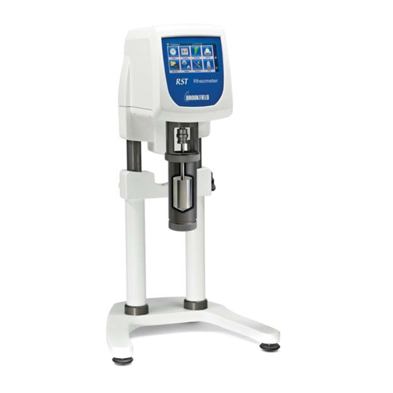
- Page 6 Figure I-1 Components: 1 Rheometer with touchscreen 5 Barcode reader 2 Measuring bob coupling 6 Clamp handle 3 Seat flange for sample cup 7 Stand 4 Stand base plate 8 Leveling screw Brookfield Engineering Labs., Inc. page 6 Manual No. M14-223...
- Page 7 8 Upper seat of work plate I.2.3 Measuring Elements and Accessories for RST-CC and RST-SST Measuring devices are not part of the standard delivery of the RST Rheometer and must be ordered according to your measuring requirements. Optional measuring devices available: coaxial standard measuring systems for RST with or without built-in temperature sensor Pt100 •...
- Page 8 USB port for connection of RST-CPS to printer, computer or USB flash drive The RST-CPS Rheometer can either be operated manually using the touch screen display or it can be operated under computer control. The RST-CPS Rheometer is supplied with direct drive current by the AC Adapter.
- Page 9 I.2.5 Elements for RST-CPS Measuring devices are not part of the standard delivery of the RST-CPS Rheometer and must be ordered according to your measuring requirements. The following types of measuring systems are suited for use with the RST-CPS Rheometer:...
- Page 10 • application software package Rheo3000 • The application software for the RST Rheometer (Rheo3000 software package) is available separately and not absolutely necessary for the operation of the measuring instrument. In the following cases, however, it is highly recommended: extensive rheological analyses •...
- Page 11 Do not take the measuring instrument into service with transport damage in evidence. Danger! Moving the measuring instrument To assemble or move the RST-CPS Rheometer, hold it nowhere but by the stand. Never hold the measuring instrument by the Measuring Head to carry it. Caution! Location Place the measuring instrument upright on a stable, level table (stand base at the bottom).
- Page 12 Danger! Protective Clothing It’s recommended to wear protective goggles, gloves and snood-type cap. Danger! General Observe all safety notes contained in this operating manual and read it through carefully. Caution! Brookfield Engineering Labs., Inc. page 12 Manual No. M14-223...
- Page 13 Danger! • liquids or corrosive chemicals. The RST Rheometer is not intended for use in a potentially hazardous environment. Samples The user should ensure that the substances placed under test do not release poisonous, toxic or flammable gases at the temperatures which they are subjected to during the testing.
- Page 14 The RST-SST Rheometer can perform viscosity measurements in original packing containers with the test material. The height of the RST-SST is adjusted by loosening the clamp handle and then moving the instrument to the desired position with the operating handle. After height adjustment the clamp handle can be fastened finger-tight again if desired.
- Page 15 II.4.3 Mounting the Workplate RST-SST This step is required only if you intend to use the workplate of the RST-SST. To mount it, proceed as follows: Place the workplate into the upper or lower seat by pushing it in laterally until it stops.
- Page 16 -20°C ... +180°C. Temperature control device The temperature control device FTK without KE cooling unit must not be used beyond the temperature range of -10°C ... Caution! +90°C! Figure II-3 Brookfield Engineering Labs., Inc. page 16 Manual No. M14-223...
- Page 17 Immersion type sample cup Measuring bob CC3-40 Measuring bob CC3-8 Assembly: Turn the RST Rheometer off with the mains switch on the back of the instrument. • If the cooling device KE is to be used, mount it first. •...
- Page 18 ME3-CP/PP. To install this optional measuring system, proceed as follows: Turn the RST Rheometer off with the mains switch on the back of the instrument • If the KE cooling unit is to be used, mount it first.
- Page 19 RST Rheometer. Assembly: Turn the RST Rheometer off with the mains switch on the back of the instrument • Slide the cooling device KE onto the RST Rheometer from below and tighten the thread.
- Page 20 It will fasten the hose (without screwing or turning) by locking in. Pull lightly to check if the hoses fit tightly. • II.5 Setup for RST-CPS II.5.1 Removing Safeguard RST-CPS To remove the safeguard: •...
- Page 21 Touch Screen Display alternately with the Date. II.5.4 AC Adapter RST-CPS The AC adapter is used to power the RST-CPS Rheometer. Do not use any other device to supply the RST-CPS Rheometer with power than the AC adapter of IP class 4/2 delivered by Brookfield.
- Page 22 For measurements without PC support the printer ® DYMO LabelWriter • This printer can be connected directly to the USB Host port of the RST Rheometer. To print the measured values during measurement you must pre-select “Printer” as output device. ® Connecting the printer DYMO LabelWriter Turn the RST Rheometer off with the mains switch on the back of the rheometer.
- Page 23 For information on the installation of the computer system, please refer to the operating instrutions of the individual devices. II.8 Cleaning The paint coat of the RST Rheometer resists most solvents and weak acids. Use a dry, clean, soft and nap-free cloth to clean the housing. Use neutral detergent liquids if necessary. Cleaning and Environment Do not use chemical products such as strong solvents or strong acids to clean the housing, especially the Touch Screen Display.
- Page 24 III Making Measurements in Standalone Mode The following chapter summarizes the operation and the menu system of the RST for the performance of manual measurements without PC. III.1 Quick Start: Run Single The following steps describe the procedure to run a test in standalone mode: 1.
- Page 25 Choices include: Cone, Cylinder, Vane, Plate, DG (Double Gap) and Custom. Your spindle type will automatically be recognized by your RST Rheometer. The “visible” box will have a check mark. Click this box if you want to remove the check mark, in which case, the spindle identity will not be displayed. Push the OK button to go to the next screen.
- Page 26 Speed Torque Shear Stress Shear Rate Figure III-8 Push OK to go to the next screen. 8. Enter the START and END values for the test type that you have chosen. Brookfield Engineering Labs., Inc. page 26 Manual No. M14-223...
- Page 27 11. Input the substance information for the test material if desired. You can use up to 25 alphanumeric characters. This is an optional screen. Push OK and the viscosity test will automatically start. 12. During the test execution, the following screen shows the parameters that are displayed: Brookfield Engineering Labs., Inc. page 27 Manual No. M14-223...
- Page 28 14. Click on the FOLDER icon. The parameters for the completed test are reviewed on the next two screens. The first screen will review the company/user information if the USER MANAGEMENT feature Brookfield Engineering Labs., Inc. page 28 Manual No. M14-223...
- Page 29 Click on MATH to review maximum average and minimum viscosity values for the completed test. III.2 Languages User screens for the RST Rheometer are available in the following languages; click on SETTINGS on the home screen (main menu), then click on LANGUAGE: German •...
- Page 30 Replace the protective foil on the display when damage or heavy wear is in evidence. After turning the RST Rheometer on, you will see the main menu. Since the RST Rheometer cannot show all main menu items at the same time, there is a second menu page to which you go with the icon “Run 4…10“...
- Page 31 !Edit Program !Explorer !Settings !Time !Counter !Zeroing !Barcode !Memory !Self Test !Temperature !USB !Language !German !English !Chinese !Japanese !Portuguese !Spanish !Polish !French !Russian !RS232 !Service !About !Activation Brookfield Engineering Labs., Inc. page 31 Manual No. M14-223...
- Page 32 • measuring systems • user management (Users) • test programs (Edit Prog) • view and manage measured data in “Explorer” • III.5.1 Units Press the Units icon in the Edit menu. Brookfield Engineering Labs., Inc. page 32 Manual No. M14-223...
- Page 33 Press the OK icon to go to a list from which you choose the measuring system to be changed. Bear in mind that the list of measuring systems consists of several pages. Move up or down through the list with the arrows. Figure III-21 Brookfield Engineering Labs., Inc. page 33 Manual No. M14-223...
- Page 34 This is where you enter the name of the measuring system using the keyboard to enter up to 25 alpha numeric characters. Push OK to confirm the name and go to the next screen where you select the measuring system type: Figure III-25 Brookfield Engineering Labs., Inc. page 34 Manual No. M14-223...
- Page 35 (mL) in the next mask and acknowledge with OK. Figure III-28 Now your new or changed measuring system is durably stored in your RST-CPS Rheometer. To correct input errors or check your entries you can always return to the previous input mask using “Back”.
- Page 36 For example, this feature provides the support capability to comply with the requirements of 21CFR Part 11 for the pharmaceutical industry which addfresses the controls for user access to the RST Rheometer. Press the “Users” icon. Switch on “User Management” by putting a check mark in the box and press OK.
- Page 37 This password is necessary for the user to gain access to the assigned features when using the instrument. Once users have been set up by the Administrator, turn off the RST Rheometer. The next time the instrument is turned on, the first screen to appear is User Names.
- Page 38 Push OK to go to the next screen to choose your measuring system. Use the down arrow to navigate to additional screens with more spindle choices: Figure III-36 Figure III-37 Brookfield Engineering Labs., Inc. page 38 Manual No. M14-223...
- Page 39 Place program blocks in sequence to create your test. For example, you can start at a low rotational speed and ramp to a higher speed, then maintain that speed at a constant value, then ramp back down to your start speed. Brookfield Engineering Labs., Inc. page 39 Manual No. M14-223...
- Page 40 Click on each program block to enter values for the test parameters. The following screens provide the choices for information that you must enter into the program test block so that you can run the test: Figure III-41 Figure III-42 Figure III-43 Figure III-44 Brookfield Engineering Labs., Inc. page 40 Manual No. M14-223...
- Page 41 1000 cP and ±10%, the limits would be 900 cP to 1100 cP. Push OK. The next screen allows you to control an alarm which is sounded by the RST Rheometer whenever the viscosity is outside the QC limits that you set. The sliding scale allows you to set the amount of time that the larm will beep for each measuring point that is outside the QC limits.
- Page 42 This feature allows you to view and manage test data. Click on the Explorer icon, and go to the next screen. Folder icons are displayed. The first icon is the SD card. III.8 Options In this menu you manage and change settings for your RST Rheometer: Figure III-47 Note that the menu has a second page: Figure III-48 Brookfield Engineering Labs., Inc.
- Page 43 This screen configures the RS232 port: Figure III-51 III.8.5 Memory This screen tells you how much free memory is available in your RST Rheometer. When you open the “Folder” icon, you can review data files stored in memory. Brookfield Engineering Labs., Inc.
- Page 44 The next icon is a folder that is called, “DATA2”, and contains the test data files from the internal memory of your RST Rheometer. Double click “DATA2” and the data files that have been stored in the RST Rheometer memory will be listed in reverse chronology – from the most recently completed test to the first test.
- Page 45 Figure III-54 III.8.12 ABOUT This screen identifies firmware and hardware information for your RST Rheometer. III.9 Run Programm 1 to 11 The procedure and functionality of “Run Program 1” is the same as for Programs 2 through 11. Click on the program icon for the test that you have stored in memory using the “Edit Program”...
- Page 46 Click the “Graph” icon (graphic representation of your measured data in real time) to see measured values for viscosity and temperature vs. time. Figure III-57 or the Math icon (mathematic evaluation of your measured data). Brookfield Engineering Labs., Inc. page 46 Manual No. M14-223...
- Page 47 • When making measurements in remote mode under PC control, follow this procedure: Connect the AC adapter. • Connect the cable between RST Rheometer and PC. • Remove any attached spindle. • Turn the power button ON and wait until the main menu is shown in the Touchscreen.
- Page 48 IV.1 Measurement Systems for RST-CC and RST-SST The following types of measuring systems are used with RST-CC and RST-SST: a) standard coaxial geometry measuring systems for measurement without thermostatic control device FTK, consisting of sample cup for (MB3-40...MB3-8 DIN and MB3-DG) •...
- Page 49 (deliverable as special accessory). In this case it is important to pay attention to the depth of immersion. Temperature control Temperature range max.: 0°C ... 90 °C! The cooling device KE is needed for an extended temperature range of -20... 180°C. Caution! Brookfield Engineering Labs., Inc. page 49 Manual No. M14-223...
- Page 50 Assembly / disassembly of measuring device Hold the measuring device with one hand by the lower part while loosening and mounting the quarter-turn fastener, or else the measuring table will fall down. Caution! Brookfield Engineering Labs., Inc. page 50 Manual No. M14-223...
- Page 51 You can use either Manual Gap Adjustment (MGA) or Automatic Gap Control (AGC). If there is a micrometer ring (Nonius) on the RST-CPS Rheometer you have an instrument with MGA. Otherwise you have to use AGC.
- Page 52 You can carry out measurements after you adjust the gap. Adjust the gap using the following procedure in Appendix B. Follow the sample procedure for making measurements as defined in the preceding section. Brookfield Engineering Labs., Inc. page 52 Manual No. M14-223...
-
Page 53: Appendix A Technical Data
Relative humidity (not condensing) in operation 20% to 80% The range depends on the used measuring system and the sample. Contact your Brookfield dealer for further information. The range depends on the temperature control. Higher temperatures are available. Contact your Brookfield dealer for further information. -
Page 54: Appendix B Rst-Cps Rheometer Gap Setting Procedure For Cone And Plate Spindles
“Loosen measuring system hexagon screw. Confirm with ‘OK’. After loosening the screw, press The RST-CPS head moves downward to the hit point. The screen will display a downward motion for the rheometer head and say: “Z-Drive moving! Please wait…” When the spindle makes contact with the plate, the next screen will appear: “Tighten measuring system screw!”... - Page 55 The procedure is similar to Run Single. Press the program button that you want to use, such as “Start Prog. 3” The sequence of screens that follows will direct you to attach the spindle. The RST-CPS will automatically set the gap and run the test.
-
Page 56: Appendix C Calibration Check
Prepare the proper sample volume for the test and condition to the defined temperature within +/- 0.1°C. Mineral oil is highly temperature sensitive, so it is important to do this correctly. If using the RST-CPS Rheometer, trim the sample around the circumference of the cone spindle. - Page 57 Repeat the test procedure if necessary. Areas for potential error are not having the proper sample volume and not conditioning the sample to the correct temperature. If the instrument fails when you repeat the calibration check, contact Brookfield or your authorized dealer. Brookfield Engineering Labs., Inc.
-
Page 58: Appendix D Symbols For Test Parameters And Units Of Measurement
Appendix D Symbols for Test Parameters and Units of Measurement Parameter Symbol Unit [min -1 ] Speed Torque [1000 ‰ = 100 mNm] Temperature [°C,°F] Time [s -1 ] Shear Rate Shear Stress [Pa] Viscosity [Pa•s, mPa•s, cP, P] Brookfield Engineering Labs., Inc. page 58 Manual No. M14-223... -
Page 59: Appendix E Data Sheets For Standard Measuring Systems
Appendix E Data Sheets for Standard Measuring Systems Table of Coaxial Cylinder Measuring Systems according to DIN 53018 / 53019 / ISO 3219 (consisting of measuring bob and sample cup) Three sample cup models are available for the RST-CC and RST-SST Rheometer: • MB3-40 ... 8 DIN •... - Page 60 Outside radius of sample cup R [mm] 21.0 Measuring length L [mm] Radius ratio $ = Error! = Error! 1.0244 Coefficient of resistance c " & " " " Measuring geometry according to DIN 54453 Brookfield Engineering Labs., Inc. page 60 Manual No. M14-223...
- Page 61 155,000 30,700 Filling quantity [mL] 3.927 1.309 2.618 Shear rate factor K [s /RPM] Shear stress factor [Pa] 16.297 2.037 0.604 ‰ Radius of measuring plate R [mm] 12.5 25.0 37.5 Brookfield Engineering Labs., Inc. page 61 Manual No. M14-223...
- Page 62 0,2094 It may be possible to use a vane spindle with the MB measuring chamber. This combination can be used to measure flurries (fluids with suspended particles). Contact Brookfield or your authorized deaer for more information. Brookfield Engineering Labs., Inc.
-
Page 63: Appendix F: Rst-Sst For Measuring In Brabender Units (Bu)
Appendix F Measuring in Brabender Units (BU) RST-SST Rheometers have firmware that will recognize spindle geometry RSS-90Y for testing according to ASTM C474. The RSS-90Y spindle has three parts: Spindle Adapter (which connects to the rheometer) BU Spindle Type A Thumb Screw (which secures the Spindle in the Spindle Adapter). -
Page 64: Appendix G Instrument Dimensions
Appendix G Instrument Dimensions RST-CC: Brookfield Engineering Labs., Inc. page 64 Manual No. M14-223... - Page 65 RST-SST: Brookfield Engineering Labs., Inc. page 65 Manual No. M14-223...
- Page 66 RST-CPS-F: Brookfield Engineering Labs., Inc. page 66 Manual No. M14-223...
- Page 67 RST-CPS-PA / -PO, RST-CPS-EH: Brookfield Engineering Labs., Inc. page 67 Manual No. M14-223...
-
Page 68: Appendix H Online Help And Additional Resources
Brookfield has its own YouTube channel. Videos posted to our website can be found here as well as other “home-made” videos made by our own technical sales group. -
Page 69: Appendix I Warranty Repair And Service
Transportation is at the purchaser’s expense. The Rheometer should be shipped in its carrying case together with all spindles originally provided with the instrument. If returning to Brookfield please contact us for a return authorization number prior to shipping.
Need help?
Do you have a question about the RST and is the answer not in the manual?
Questions and answers