Table of Contents
Advertisement
Brookfield Engineering Laboratories, Inc.
BROOKFIELD DV-III ULTRA
Programmable Rheometer
Operating Instructions
Manual No. M98-211-E0912
Boston • Chicago • London • Stuttgart • Guangzhou
with offices in:
BROOKFIELD ENGINEERING LABORATORIES, INC.
11 Commerce Boulevard, Middleboro, MA 02346 USA
T
508-946-6200
800-628-8139 (USA excluding MA)
or
EL
F
508-946-6262
I
http://www .brookfieldengineering.com
AX
NTERNET
SPECIALISTS IN THE
MEASUREMENT AND
CONTROL OF VISCOSITY
Page 1
Manual No. M98-211-E0912
Advertisement
Table of Contents

Related Manuals for Brookfield DV-III ULTRA


Summary of Contents for Brookfield DV-III ULTRA
-
Page 1: Operating Instructions
BROOKFIELD DV-III ULTRA Programmable Rheometer Operating Instructions Manual No. M98-211-E0912 SPECIALISTS IN THE MEASUREMENT AND CONTROL OF VISCOSITY Boston • Chicago • London • Stuttgart • Guangzhou with offices in: BROOKFIELD ENGINEERING LABORATORIES, INC. 11 Commerce Boulevard, Middleboro, MA 02346 USA... - Page 2 Brookfield Engineering Laboratories, Inc. Page 2 Manual No. M98-211-E0912 Brookfield Engineering Laboratories, Inc. Page 2 Manual No. M/98-211-B0104...
-
Page 3: Table Of Contents
III.2 Preparations for Making Measurements ................28 III.3 Selecting a Spindle/Speed ....................30 III.4 Multiple Data Points .......................30 IV. Programming the DV-III Ultra and Data Collection Methods/Analysis ..31 IV.1 Programming Concepts ......................31 IV.2 DV-III Speed/Time Pair Programs for Making Viscosity Measurements .......32 IV.3 Bevis Programs for Making Viscosity Measurements ............42... - Page 4 Appendix G - DV-III Ultra Stand Assembly ..............109 Appendix H - DVE-50A Probe Clip ..................110 Appendix I - DV-III Ultra to Computer Command Set ............ 111 Appendix J - Fault Diagnosis and Troubleshooting .............115 Appendix K - Online Help and Other Resources ............118 Appendix L - Warranty Repair and Service ..............119...
-
Page 5: Introduction
Solutions to Sticky Problems”, a copy of which was included with your DV-III Ultra. The principle of operation of the DV-III Ultra is to drive a spindle (which is immersed in the test fluid) through a calibrated spring. The viscous drag of the fluid against the spindle is measured by the spring deflection. -
Page 6: Yield Stress Measurement
Figure I-1 The shear stress measurement range of the DV-III Ultra (in Pascals) is determined by the size and shape of the vane spindle and the full scale torque range of the calibrated spring. Maximum Torque Value... -
Page 7: Components
Please check to be sure that you have received all components, and that there is no damage. If you are missing any parts, please notify Brookfield Engineering or your local Brookfield agent immediately. Any shipping damage must be reported to the carrier. -
Page 8: Dimensional Information
I.5 Dimensional Information Brookfield Engineering Laboratories, Inc. Page 8 Manual No. M98-211-E0912 Brookfield Engineering Laboratories, Inc. Page 8 Manual No. M/98-211-B0104... -
Page 9: Utilities
0 - 1 Volt DC (0 - 100% torque) Analog Temperature Output: 0 - 4 Volts DC (10mv / °C) Printer Output: Centronics, parallel or serial Computer Interface: RS-232 Torque Accuracy: ±1.0% of full scale range Torque Repeatability: ±0.2% Brookfield Engineering Laboratories, Inc. Page 9 Manual No. M98-211-E0912... - Page 10 If you ordered the ball bearing suspension system with your new instrument, please note the following: 1) The ball bearing suspension in your Brookfield instrument is noted on the serial tag on the back of the head by the letter "B" after the mode.
-
Page 11: Safety Symbols And Precautions
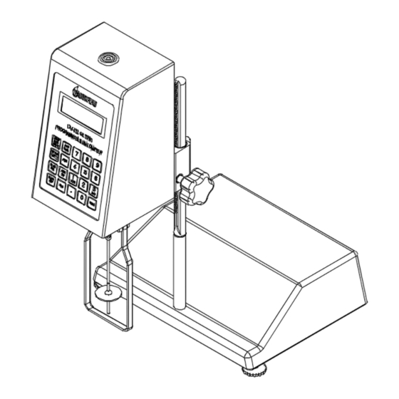
Instrument intended for indoor use only. I.9 Data Retention The DV-III Ultra will save spindle parameters (used to calculate centipoise, shear rate and shear stress), default settings and the test data from the last program test run when the rheometer is turned off or there is a power failure. - Page 12 (see Figure I-4). The upright rod (item #1) is held in place with the jam nut (item #4) which is attached from the bottom of the base. Tighten this nut with a suitable wrench (spanner). DV-III Ultra Stand Assembly CLAMP ASSEMBLY NOTE: “FRONT” FACES TOWARD YOU.
- Page 13 8) Make sure that the AC power switch at the rear of the base unit is in the OFF position. Connect the AC plug to the socket on the back of the DV-III Ultra base and plug it into the appropriate AC line.
- Page 14 Parallel Printer Figure I-6 The DV-III Ultra must be earth grounded to ensure against electronic failure!! 9) Temperature monitoring is assured (after the instrument has stabilized) to within ±1.0°C in the range -100°C to +150°C and within 2°C in the range 150°C to 300°C.
-
Page 15: Connections
THERMOSEL CONTROLLER AND TC SERIES TEMPERATURE BATHS Earlier model baths with programmable Brookfield Controllers will also work. The DVP-141 cable is used to connect the serial port on the DV-III Ultra base to the serial port on the controller. This cable is supplied with the controller/bath. -
Page 16: Key Functions
STRIP CHART RECORDER DVP-96Y cable is used to connect the serial port on the DV-III Ultra to the input block of the strip chart recorder. This cable is supplied with a Brookfield strip chart recorder. I.12 Key Functions Figure I-7 shows the control keys on the face of the DV-III Ultra Rheometer. The following describes each key’s function. -
Page 17: Cleaning
Allows you to review/modify an existing test program. Execute a Bevis program. PROG RUN PROG Execute DV-III Ultra speed/time pair program. NUMBER KEYS (0 through 9) Sets speeds and choose items from various dialog screens and the option menu. ENTER... -
Page 18: Getting Started
The Rheometer will guide you through the procedure, as follows: Turn power switch on; as shown in Figure II-1, the screen indicates that the DV-III Ultra is in the standalone mode (is not connected to a computer) and gives the version of the operating firmware (the built in program which controls the instrument) and a two-digit alphanumeric code which indicates the Model number (see Table D2 in Appendix D;... - Page 19 1. Motor Status and Current Rheometer Speed The DV-III Ultra motor can be OFF, ON at 0.0 rpm or ON at a speed greater than 0.0 rpm. When the motor is OFF, "OFF" will be displayed and no speed entry will be accepted. When the motor is ON, the actual speed of rotation will be displayed.
- Page 20 Table II-1 OUT OF RANGE INDICATORS The DV-III Ultra is capable of measuring instrument torque within the range of 0 to 100%. Based on this measurement, viscosity and shear stress are calculated. Brookfield recommends that data be collected only in the range of 10 to 100%. Any data collected outside of this range is considered invalid.
-
Page 21: Ii.3 Spindle Entry
MOTOR ON/OFF/ESCAPE To enter a new spindle into memory, use the following procedures. Press and Hold the motor on/off and “9” key on power up. The screen in Figure II-9 appears. Brookfield Engineering Laboratories, Inc. Page 21 Manual No. M98-211-E0912 Brookfield Engineering Laboratories, Inc. - Page 22 (example: spindle AA = SMC = 1.0 SRC = 2.0). If you are adding additional spindles, press the “enter” key. You can enter up to 5 special spindles. Brookfield Engineering Laboratories, Inc. Page 22 Manual No. M98-211-E0912...
-
Page 23: Ii.4 Direct Speed Entry
Here, the user intends to enter a speed of 112 RPM, has pressed the “1” key twice and is about to press the “2” key. If the user makes more than five (5) key presses, the DV-III Ultra control program will “roll” the cursor back to the first character of the field and begin to overwrite the previous data entry. -
Page 24: Ii.5 External Control
V0.0 HA EXTERNAL Figure II-21 The DV-III Ultra may be set to stand alone mode by turning it OFF and ON again and selecting "Stand Alone" or by removing the cable (DVP-80 or DVP-202) prior to turning the DV-III Ultra Note: The DV-III Ultra cannot communicate with RHEOLOADER or EZ- Yield software in the external control mode. -
Page 25: Ii.6 Preventative Maintenance
We recommend that you check the calibration of your DV-III Ultra on a regular basis. The frequency of calibration checks should be set based on your use of the instrument and the significance of the data. We generally recommend a frequency of 1 month. - Page 26 • Wells/Brookfield sample cups should be handled carefully to prevent scratches or nicks. Do not use abrasive cleaners or cloths. • Store all spindles in the protective case in which they were supplied. • Do not store spindles attached to the unit.
-
Page 27: Making Viscosity And Yeild Measurements
Dial Reading Viscometer and DV series of Digital Viscometers. If you have experience with other Brookfield equipment, this section will give you the quick steps for taking a viscosity reading. If you have not used a Brookfield Viscometer before, skip this section and go to Section III.2 for a detailed description. -
Page 28: Iii.2 Preparations For Making Measurements
After a few seconds, your PC will automatically show the Graphs page in the EZ-Yield software program, indicating that the test has begun. The DV-III Ultra will send data to the PC and the graph of the yield stress flow behavior will be captured. The Data page in the software will record the actual numerical values for shear stress. - Page 29 If you are using an accessory device such as a Small Sample Adapter, the complete kit must be configured for the EZ-Lock Unit to ensure proper alignment and spindle immersion. Contact Brookfield for more information. Figures III-1a and III-1b shows the method for both connection systems.
-
Page 30: Iii.3 Selecting A Spindle/Speed
The test is conducted with one spindle at one speed. The data point is a useful bench mark for the go/no-go decision in a production setting. The DV-III Ultra can be used for single point measurement. -
Page 31: Programming The Dv-Iii Ultra And Data Collection Methods/Analysis
The DV-III Ultra programming technique uses speed/time pairs, when making viscosity measurements, to control the DV-III Ultra. A program consists of multiple lines (up to 25) instructing the rheometer to operate at a particular speed for some period of time. As an example, we can instruct the DV-III... -
Page 32: Iv.2 Dv-Iii Speed/Time Pair Programs For Making Viscosity Measurements
These speed/time pairs instruct the rheometer to operate at a speed of rotation for a certain period of time. Programs can be created with up to 25 steps. The DV-III Ultra can store up to 10 programs. Upon completion of a program, the data may be viewed on the DV-III Ultra display, analyzed or printed to an attached parallel or serial printer. - Page 33 On entry to this screen, the underscore cursor would be flashing (as shown) under the first digit of the step RPM. Use the numeric keys to make changes to the step speed, repeating the input as many times as required until satisfied. Brookfield Engineering Laboratories, Inc. Page 33 Manual No. M98-211-E0912...
- Page 34 NEW SPEED SET #3 STEP 01 STEP RPM = 0.0 STEP TIME = 00:05 Figure IV-8 Brookfield Engineering Laboratories, Inc. Page 34 Manual No. M98-211-E0912 Brookfield Engineering Laboratories, Inc. Page 34 Manual No. M/98-211-B0104...
- Page 35 This message simply asks the user to make sure the printer is ready (it’s on-line and has paper in it) and then awaits for the PRINT key to be pressed. When it is pressed, the DV-III Ultra will send the following data to the attached printer:...
- Page 36 Since speed sets can contain twenty-five (25) separate speeds, printing the speeds that comprise a speed set will be of great help in allowing the user to fully exercise the power of the DV-III Ultra. After the printing is complete, the user will be returned to the display of Figure IV-9.
- Page 37 CLEAR SET:_ Figure IV-13 Pressing the “3” key will cause the DV-III Ultra to take no action and will return the user to the CLEAR SPEED SET opening screen, Figure IV-11. Any attempt to delete an in-use speed (“3” for instance) will cause the DV-III Ultra to issue a “beep beep” with no action being taken. Thus no active (i.e.
- Page 38 At this point, the user would turn the viscometer motor on by pressing the MOTOR ON/OFF/ESCAPE key. This will cause the viscometer to start running at the first selected program speed. Brookfield Engineering Laboratories, Inc. Page 38 Manual No. M98-211-E0912 Brookfield Engineering Laboratories, Inc.
- Page 39 The item to note here is the message being displayed on line 3 informing the user that the program is at speed #02 of the 12 speeds comprising speed set #02. The DV-III Ultra will continue to operate at 112 RPM until the key is pressed.
- Page 40 ON (PRTN) (The automatic ramping to the next speed will be interpreted by the DV-III Ultra as if the ENTER key had been pressed, causing the printer output).
- Page 41 The user may stop program mode operation at any time by pressing the MOTOR ON/OFF/ESCAPE anytime during program operation. The following message would be displayed: PROGRAM STOPPED PRESS ANY KEY Figure IV-29 Brookfield Engineering Laboratories, Inc. Page 41 Manual No. M98-211-E0912...
-
Page 42: Iv.3 Bevis Programs For Making Viscosity Measurements
Programs can include up to 25 commands with a maximum data count of 800. The DV-III Ultra can store up to 10 programs. Upon completion of the program the data may be viewed on the DV-III Ultra display, analyzed or printed to an attached parallel or serial printer. -
Page 43: Iv.3.1.1 Description Of B.e.v.i.s. Commands
(°C) specified value. 16 character (or less) The specified message is displayed on the top line of the DV-III Ultra dis text message play while PRESS A KEY is displayed on the bottom line of the DV-III Ultra. The program waits at this step until a viscometer key is pressed. - Page 44 This parameter is entered into the last column of the grid. Select the COM (RS-232) port the Programmable DV-III Ultra Rheometer is connected to from the COM Port drop down list. Low number generally represent RS-232 Ports. High number generally represent USB Ports.
- Page 45 LOAD TO SLOT#x where x is slot 1,2,3, or 4. • With the LOAD TO SLOT #x screen displayed, choose a store slot using the DV-III Ultra arrow keys, then press the ENTER/AUTORANGE key on the Rheometer. If after five sec- onds, the Rheometer cannot communicate with the RheoLoader program, the B.E.V.I.S.
-
Page 46: Iv.3.1.2 Example Programs
DV-III Ultra. When the download is complete, the DV-III Ul- tra displays DOWNLOAD DONE TO EXIT PRESS A KEY. At this point, the program in the DV-III Ultra can be printed and/or run from the Rheometer. Click on this button to exit the RheoLoader software. -
Page 47: Iv.3.2 Running Bevis Programs In Standalone Mode
The B.E.V.I.S. program menu is accessed by pressing the PROG key and selecting number 2, 2 = B.E.V.I.S. The loading and execution of B.E.V.I.S. programs are described in the following sections. Brookfield Engineering Laboratories, Inc. Page 47 Manual No. M98-211-E0912... - Page 48 See Section VI. RHEOLOADER for information on creating and downloading B.E.V.I.S. programs. DOWNLOAD A PROGRAM DOWNLOADING BEVIS PROGRAM TO SLOT #2 Figure IV-35 Brookfield Engineering Laboratories, Inc. Page 48 Manual No. M98-211-E0912 Brookfield Engineering Laboratories, Inc. Page 48 Manual No. M/98-211-B0104...
-
Page 49: Iv.4 Choosing The Best Data Collection Method For Viscosity Tests
SINGLE SPEED Single speed measurements may be made by direct speed commands on the DV-III Ultra keypad. Viscosity and % Torque are read directly from the display. This technique offers the simplicity of the Brookfield Dial Viscometer. Multiple data points may be gathered by issuing multiple speed commands. -
Page 50: Iv.5 Data Analysis For Viscosity Tests
(See Appendix for more information on math models.) The DV-III Ultra does not allow for data sets to be edited. Programs must be constructed to conform with the following data requirements if math models are to be used: •... - Page 51 PRINT key while any of the above screens are being displayed causing the following to be printed: STANDARD CASSON PRINTOUT Sample Name: ____________________________________________________ Operator Name: ___________________________________________________ Date: 01/14/1999 Time: 02:27 Math Model Results: CASSON (STANDARD) Brookfield Engineering Laboratories, Inc. Page 51 Manual No. M98-211-E0912...
- Page 52 Confidence of Fit: 63.6 The equation for each model is described below with a definition of parameters. Please contact Brookfield or an authorized representative if further information is required. The confidence of fit parameter used in all of the models is an indication Note: of how well the model fits the data set.
- Page 53 = Consistency Multiplier = Rotational Speed (RPM) = Shear Sensitivity Factor The calculated parameters for this model are: Shear Sensitivity Factor (no units) 10 RPM Viscosity (cP or mPa•s) Confidence of Fit Brookfield Engineering Laboratories, Inc. Page 53 Manual No. M98-211-E0912...
-
Page 54: Iv.6 Automated Data Gathering And Analysis Using Rheocalc
Auto range feature which shows in screen display the complete viscosity range which can be measured at any shear rate for a specific spindle geometry The following figures show the principal screens associated with Rheocalc: Figure IV-43: Dashboard Screen Brookfield Engineering Laboratories, Inc. Page 54 Manual No. M98-211-E0912 Brookfield Engineering Laboratories, Inc. - Page 55 Figure IV-44: Test Screen Figure IV-45: Run/Data Screen Brookfield Engineering Laboratories, Inc. Page 55 Manual No. M98-211-E0912...
- Page 56 Figure IV-46: Setup Screen Figure IV-47: Analysis Screen Brookfield Engineering Laboratories, Inc. Page 56 Manual No. M98-211-E0912 Brookfield Engineering Laboratories, Inc. Page 56 Manual No. M/98-211-B0104...
-
Page 57: Iv.7 Math Models
This model should be used with non-Newtonian, time-independent fluids that do not have a yield stress. These fluids will begin to flow under any amount of shear stress. Graphs of such material generally intersect the y-axis at 0. Brookfield Engineering Laboratories, Inc. Page 57 Manual No. M98-211-E0912... -
Page 58: Iv.7.2 The Herschel/Bulkley Model
The closer n is to 0, the more shear thinning the material is. When n > 1 the product is shear-thickening or Dilatant. It’s apparent viscosity increases as shear rate increases. Brookfield Engineering Laboratories, Inc. Page 58 Manual No. M98-211-E0912 Brookfield Engineering Laboratories, Inc. - Page 59 With a flow index of 0.66, this batch is also less shear thinning than normal. Pump and mixer speeds must be adjusted before using this material. Brookfield Engineering Laboratories, Inc. Page 59 Manual No. M98-211-E0912...
-
Page 60: Iv.7.3 The Bingham Model
(Products that have a yield stress only begin to flow after a certain amount of shear stress is applied. They are also called “viscoplastic”. Their shear stress vs. shear rate graphs intersect the y-axis at a point greater than 0.) Brookfield Engineering Laboratories, Inc. Page 60 Manual No. M98-211-E0912 Brookfield Engineering Laboratories, Inc. -
Page 61: Iv.7.4 The Casson Model
) which is the amount of shear stress required to initiate flow, and the product’s plastic viscosity, , which is the viscosity of the product η after it yields. € Figure IV-51 Brookfield Engineering Laboratories, Inc. Page 61 Manual No. M98-211-E0912... - Page 62 € € € model determines yield and flow properties under specified conditions and closely approximates the plastic behavior of chocolate before final processing. Brookfield Engineering Laboratories, Inc. Page 62 Manual No. M98-211-E0912 Brookfield Engineering Laboratories, Inc. Page 62 Manual No. M/98-211-B0104...
- Page 63 The IPC Paste Model was developed for solder pastes. It calculates the viscosity of solder pastes at 10rpm. The IPC Paste Model requires that the product be tested with a Brookfield Spiral Adapter at multiple speeds. More details can be found in the IPC-TM-650 Test Methods Manual (methods 2.4.34.2 and 2.4.3).
- Page 64 Figure IV-52 Figure IV-53 Brookfield Engineering Laboratories, Inc. Page 64 Manual No. M98-211-E0912 Brookfield Engineering Laboratories, Inc. Page 64 Manual No. M/98-211-B0104...
-
Page 65: Iv.8 Yeild Stress Test Programs And Test Samples
Brookfield. Therefore, you will need to use the EZ-Yield Software on your PC to create yield test programs. Once a yield test program has been downloaded from your PC to the DV-III Ultra, you will be able to run tests by following the instructions in this section. - Page 66 Program Number This is the number of the memory slot in the DV-III Ultra Rheometer to which the test parameters will be loaded. There are ten (10) slots, numbered from 0 through 9.
- Page 67 Run Speed Run Speed is the motor speed for the DV-III Ultra at which the material is tested. It is common for materials to appear stiffer when tested at higher speeds. That is, the slope of the stress-vs.-strain curve increases with increasing speed.
-
Page 68: Iv.8.2 Toolbar And Menu Options
#3.DB chocolate syrup #3.DB hair gel #4.DB chocolate syrup #4.DB petroleum jelly #1.DB ketchup #1.DB petroleum jelly #2.DB ketchup #2.DB Figure IV-57 Brookfield Engineering Laboratories, Inc. Page 68 Manual No. M98-211-E0912 Brookfield Engineering Laboratories, Inc. Page 68 Manual No. M/98-211-B0104... - Page 69 Preview window. Once this window is displayed, clicking the p button sends the report to the riNt selected printer. The functions of the buttons on the toolbar are described below: Brookfield Engineering Laboratories, Inc. Page 69 Manual No. M98-211-E0912...
- Page 70 Load Report Previously saved reports can be loaded into the Print Report Preview window. Only reports saved to the QuickReport (*.QRP) format can be reloaded. Brookfield Engineering Laboratories, Inc. Page 70 Manual No. M98-211-E0912 Brookfield Engineering Laboratories, Inc. Page 70...
- Page 71 The program numbers refer to the memory locations in the DV-III Ultra Rheometer. After a few seconds, the DV-III Ultra tells EZ-Yield that the test has begun. Once all optional preparation steps have been performed by the rheometer, EZ-Yield begins to receive data as the test runs.
-
Page 72: Iv.8.3 Data Page
Data Page Figure IV-60 Use this page to load, save, print, and export data taken with the DV-III Ultra Rheometer. The file name (including path) of the data currently loaded is displayed at the top of the page. The test parameters used to collect the data are displayed on the left of the page in the box labeled “Parameters Used To Collect Data”. - Page 73 See Section IV.8.6.2 - Printing a Program - for more information regarding this window. All open, save, and print operations selected while this page is displayed will open, save, and print data, but NOT test parameters. Brookfield Engineering Laboratories, Inc. Page 73 Manual No. M98-211-E0912...
-
Page 74: Iv.8.4 Graphs Page
The three (3) toolbars on the right side of the page can be resized and moved within the confines of the toolbar box by clicking and dragging the toolbar sizer located to the left of the toolbar title. Brookfield Engineering Laboratories, Inc. Page 74 Manual No. - Page 75 On-Line Plotting be plotted on both graphs during the run cycle of a yield test. Keep in mind that the DV-III Ultra Rheometer must be communicating with the host PC and EZ-Yield in order for this data to be plotted.
-
Page 76: Iv.8.5 Examples Of Yield Test Programs
The V-73 vane spindle was selected because it is the smallest and could be completely immersed in the shallow jar. An RVDV-III Ultra Rheometer was used for the test. Brookfield Engineering Laboratories, Inc. Page 76 Manual No. M98-211-E0912 Brookfield Engineering Laboratories, Inc. -
Page 77: Iv.8.5.2 Example Application: Hand Cream
In this case, either a lower Run Speed might be desired or a smaller Base Increment. Both would increase the density of data points and result in a more accurate or repeatable test result. Brookfield Engineering Laboratories, Inc. Page 77... -
Page 78: Iv.8.5.3 Example Application: Ketchup
Significant differences between the name brand and the store brand can be characterized by such a test as shown in Figure IV-66. Both the slope of the stress/strain curves and the yield points are clearly different. Brookfield Engineering Laboratories, Inc. Page 78 Manual No. M98-211-E0912 Brookfield Engineering Laboratories, Inc. - Page 79 Figure IV-65 Figure IV-66: Ketchup Comparison Samples Brookfield Engineering Laboratories, Inc. Page 79 Manual No. M98-211-E0912...
-
Page 80: Iv.8.5.4 Torque Vs. Time For Various Food Products
(<10%), then try using a faster speed or larger spindle to get a larger torque reading. Alternatively, a DV-III Ultra Rheometer with a more sensitive spring could be used as well; e.g., RVDV-III Ultra instead of HBDV-III Ultra. - Page 81 IV.8.6 Running Yield Test Programs in Stand-Alone Mode This section explains how to use the DV-III Ultra Rheometer in standalone mode. There are no test programs stored in instrument memory when the DV-III Ultra is shipped from Brookfield. Therefore, you will need to review the preceding section on the EZ-Yield Software which explains how to create test programs.
- Page 82 (in seconds) that counts down from the user defined pre-shear time. A Pre-shear step allows the sample to be conditioned before the actual test is started. In Figure IV-72, the pre-shear speed is 10 rpm and the pre-shear time is 30 seconds. Brookfield Engineering Laboratories, Inc. Page 82 Manual No. M98-211-E0912 Brookfield Engineering Laboratories, Inc.
- Page 83 At this point, pressing the eNter key starts the test again starting from whichever Run screen is applicable (see Figures IV-72 through IV-75). Pressing the eSC key returns the display to that of Figure IV-70, reminding you which spindle should be used. Brookfield Engineering Laboratories, Inc. Page 83 Manual No. M98-211-E0912...
- Page 84 Run screen (Figure IV-72 through IV-75). When the test is complete, the results are sent out of both the parallel and serial (RS-232) ports. Brookfield Engineering Laboratories, Inc. Page 84 Manual No. M98-211-E0912 Brookfield Engineering Laboratories, Inc.
-
Page 85: Iv.8.6.1 Data Output
(displayed if test fails due to resultant yield stress being above high limit; see Section IV.8.6.3) 6. Test (test number: test name) Cancelled Test Failed = Cancelled By User (displayed if test fails due to cancellation by the user) Brookfield Engineering Laboratories, Inc. Page 85 Manual No. M98-211-E0912... -
Page 86: Iv.8.6.2 Printing A Program
Wait Time (sec): 0010 Run Parameters ------------------ Run Speed (rpm): 0.5 Base Increment (msec): 0100 Torque Reduction (%): 100 Average (readings): 05 Limits (Low/High) (Pa):0090/0100 Brookfield Engineering Laboratories, Inc. Page 86 Manual No. M98-211-E0912 Brookfield Engineering Laboratories, Inc. Page 86 Manual No. M/98-211-B0104... -
Page 87: Iv.8.6.3 Test Results
Stress is not reached before the measured % Torque value reaches 100%, an Over-Range error causes the test to end. The following is sent to an attached printer: Test (#5: Sample Tst) Complete Test Failed = Over-range Brookfield Engineering Laboratories, Inc. Page 87 Manual No. M98-211-E0912... - Page 88 Test Failed = Cancelled By User The following screen is displayed: #5: Sample Tst S:71 USER TERMINATED TEST PRESS ESC OR ENTER Figure IV-88 Brookfield Engineering Laboratories, Inc. Page 88 Manual No. M98-211-E0912 Brookfield Engineering Laboratories, Inc. Page 88 Manual No. M/98-211-B0104...
-
Page 89: Options
DV-III Ultra try to establish communication. When communication is established, "off" will be change to "on". Temperature control will always be set to "off" when the DV-III Ultra is turned When communication is established, Line 1 of the default screen will be modified. The temperature field will show "CTLR"... -
Page 90: Print
V.2 Print 1. Change the time interval that is used when the DV-III Ultra is printing continuously. Data is entered in the format of MM:SS. For example: an interval of one minute and 30 seconds is entered as: 01:30. The change is initiated by pressing the 1 key. Once the time interval is input, it must be accepted by pressing the key. -
Page 91: Set Temperature
The Review Data menu allows data review of the most recently completed speed set program. Data may be reviewed on the DV-III Ultra screen, on a serial printer, or both. The procedure for reviewing data after a test is as follows: 1) Run a DV-III or B.E.V.I.S. - Page 92 Figure V-4 Review data notes: 1) The DV-III Ultra stores data from the most recent speed set program test. When a subsequent speed set program is run, any test data in memory will be overwritten and the previous data will be lost.
-
Page 93: Timed Data Collection
TIMED STOP The DV-III Ultra will operate at a single RPM for a specified period of time. Time and speed are entered using the number keys and key. The test will begin immediately upon the... - Page 94 TIMED AVERAGE The DV-III Ultra will collect a specified number of data points over a period of time and present the average reading (arithmetic average). Time, speed and the number of data points are entered using the number keys and key.
-
Page 95: Appendix A - Cone/Plate Rheometer Set-Up
APPENDIX A - Cone/Plate Rheometer Set-Up This Cone/Plate version of the DV-III Ultra uses the same operating instruction procedures as described in this manual. However, the “gap” between the cone and the plate must be verified/adjusted before measurements are made. This is done by moving the plate (built into the sample cup) up towards the cone until the pin in the center of the cone touches the surface of the plate, and then by separating (lowering) the plate 0.0005 inch (0.013mm). -
Page 96: Electronic Gap Setting Features
Electronic Gap Setting feature. Note: The “CPE” cone or cup cannot be used with earlier DV-III Ultra cone/plate Viscometers (below S/N50969) which do not have the Coupling Nut electronic gap setting feature. -
Page 97: Setting The Gap
1. The cup may be removed and replaced without resetting the gap if the micrometer adjustment ring has not been moved. 2. Remove the spindle from the viscometer when cleaning. 3. Re-establish the hit point every time the spindle is attached/detached. Brookfield Engineering Laboratories, Inc. Page 97 Manual No. M98-211-E0912 Brookfield Engineering Laboratories, Inc. -
Page 98: Verifying Calibration
Do not use a silicone viscosity standard fluid with a viscosity value greater than 5000 cP with a Cone/Plate. Brookfield offers a complete range of mineral oil viscosity standards suitable for use with Cone/Plates for viscosities above 5,000 cP or shear rates above 500 sec ;... -
Page 99: Appendix B - Viscosity Ranges
The table below (Universal Spindle Ranges) lists the Spindle Range Coefficients for all spindles used on DV-III Ultra Rheometers. Dividing the coefficient number by any of the 2,500 Rheometer speeds will give the full scale viscosity range for a Rheometer/spindle/speed combination. - Page 100 LV spindle ranges are calculated with the LV Guardleg in use. Determine the full scale viscosity range of the LV3 spindle running on an RV series Example 1: Rheometer at 45 RPM. Spindle Speed = 45 RPM Brookfield Engineering Laboratories, Inc. Page 100 Manual No. M98-211-E0912...
- Page 101 Full Scale Viscosity Range = 5,120,000 = 49,468 cP (mPa•s) 103.5 Note: The maximum viscosity that should be taken from the DV-III Ultra Rheometer is at 100% of any full scale spindle/speed range. LV (#1-4) and RV, HA, HB (#1-7) Spindles...
- Page 102 6.4 - 2,000 25.6 - 2,000 Note: LV DV-III Ultra - Minimum viscosity, 1.0 cP at 60RPM, 10% of full scale range. Note: RV,HA,HB-III - Minimum viscosity; 3 cP, 6 cP and 24 cP, at 230.9 RPM, 10% of full scale range.
- Page 103 3,900 - 4,686,500 50,000 - 50,000,000 100,000 - 100,000,000 400,000 - 400,000,000 7,800 - 9,373,000 100,000 - 100,000,000 200,000 - 200,000,000 800,000 - 800,000,000 Brookfield Engineering Laboratories, Inc. Page 103 Manual No. M98-211-E0912 Brookfield Engineering Laboratories, Inc. Page 103 Manual No. M/98-211-B0104...
- Page 104 2) Viscosity measurements should be taken under laminar flow conditions, not under turbulent flow conditions. The first consideration has to do with the precision of the instrument. All DV-III Ultra Rheometers have a full scale range precision of (+/-) 1% of any spindle/speed combination. We discourage taking readings below 10% of range because the potential viscosity error of (+/-) 1% is a relatively high number compared to the instrument reading.
-
Page 105: Appendix C - Variables In Viscosity Measurements
Rheometer at a constant speed, recording viscosity (cP) values over time and find that the viscosity (cP) values decrease with time, the material is thixotropic. Brookfield publication, “More Solutions to Sticky Problems” includes a more detailed discussion of rheological properties and non-Newtonian behavior. Rheometer Related Variables Most fluid viscosities are found to be non-Newtonian. - Page 106 5) Spindle used (if using LVDV-III Ultra (#1-4) or RVDV-III Ultra (#1-7) attach the guard leg) 6) Test speed or speeds (or the shear rate) 7) Length of time or number of spindle revolutions to record viscosity. Brookfield Engineering Laboratories, Inc. Page 106 Manual No. M98-211-E0912...
-
Page 107: Appendix D1 - Spindle And Model Codes For Viscosity Tests
APPENDIX D1 - Spindle and Model Codes for Viscosity Tests Each spindle has a two digit code which is entered using the SPDL key on the DV-III Ultra key pad. The entry code allows the DV-III Ultra to calculate Viscosity, Shear Rate and Shear Stress values. - Page 108 SSA DIN spindle for 7R 12.09 1.29 or 7RP chamber ULA DIN spindle 1.22 1.29 ULA DIN spindle 3.65 1.29 ULA DIN spindle 12.13 1.29 When using Spindle 4B2 select spindle entry code 64 Brookfield Engineering Laboratories, Inc. Page 108 Manual No. M98-211-E0912...
- Page 109 2.5xHADV-III Ultra HBDV-III Ultra 2xHBDV-III Ultra 2.5xHBDV-III Ultra 5xHBDV-III Ultra The full scale viscosity range for any DV-III Ultra model and spindle may be calculated using the equation: 10,000 ______ Full Scale Viscosity Range [cP] = TK ∗ SMC ∗...
- Page 110 The SMC value for a spindle may be calculated as follows: a) For new spindle conditions you calculate the SMC using a Newtonian fluid of known viscosity (Brookfield Viscosity Standard). This is done in the container with the new dimensions at the controlled temperature specified for the viscosity standard fluid.
- Page 111 .803 Note: If secondary immersion mark is selected, the YMC value is doubled. The full scale Yield Stress range for any DV-III Ultra model and spindle may be calculated using the equation: Full Scale Yield Stress Range (Pa) = TK x YMC x 10...
- Page 112 5xHB 400 - 4000 Calculations for Shear Stress in Yield Test The following equations can be used to calculate the shear stress values after each packet of data is obtained from the DV-III Ultra. τ Where: τ = Yield Stress...
- Page 113 (time for 0% to 100% spring windup during calibration) Base increment (milliseconds) base increment calibration torque (%torque/base increment) Speed (rpm) Calibration speed (rpm) (fixed at 0.1 rpm) Brookfield Engineering Laboratories, Inc. Page 113 Manual No. M98-211-E0912 Brookfield Engineering Laboratories, Inc. Page 113 Manual No. M/98-211-B0104...
- Page 114 For more help you can go to the website, www.brookfieldengineering.com, and download the video. The accuracy of the DV-III Ultra is verified using viscosity standard fluids which are available from Brookfield Engineering Laboratories or your local Brookfield agent. Viscosity standards are Newtonian, and therefore, have the same viscosity regardless of spindle speed (or shear rate).
- Page 115 Brookfield Viscosity Standard Fluid - General Information We recommend that Brookfield Viscosity Standard Fluids be replaced on an annual basis, one year from date of initial use. These fluids are pure silicone and are not subject to change over time. However, exposure to outside contaminants through normal use requires replacement on an annual basis.
- Page 116 1) Place the viscosity standard fluid (in the proper container) into the water bath. 2) Lower the DV-III Ultra into measurement position (with guard leg if LV or RV series Rheometer is used). 3) Attach the spindle to the Rheometer. If you are using a disk shaped spindle, avoid trapping air bubbles beneath the disk by first immersing the spindle at an angle, and then connecting it to the Rheometer.
- Page 117 1) Put the proper amount of viscosity standard fluid into the UL Tube. (Refer to the UL Adapter instruction manual). 2) Attach the spindle (with extension link and coupling nut) onto the DV-III Ultra. 3) Attach the tube to the mounting channel.
- Page 118 1) Place the viscosity standard fluid (in the proper container) into the water bath. 2) Attach the spindle to the viscometer. Attach chamber (SA-1Y) and clamp to the viscometer. 3) Lower the DV-III Ultra into measurement position. Operate the viscometer at 50 or 60 RPM until the chamber is fully flooded.
- Page 119 1) The spindle must rotate at least five (5) times before a viscosity reading is taken. 2) The use of Brookfield Viscosity Standard fluids in the range of 5 cP to 5000 cP is recommended for cone/plate instruments. Please contact Brookfield Engineering Laboratories or an authorized dealer if your calibration procedure requires more viscous standards.
-
Page 120: Appendix F - The Brookfield Guardleg
The current guard leg is a band of metal in the shape of the letter U with a bracket at the top that attaches to the pivot cup of a Brookfield Viscometer/Rheometer. Because it must attach to the pivot cup, the guard leg cannot be used with a Cone/Plate instrument. - Page 121 Brookfield factor if the boundary conditions are not those specified by Brookfield. The guard leg is a part of the calibration check of the Brookfield LV and RV series Viscometer/Rheometer. Our customers should be aware of its existence, its purpose and the effect that it may have on data. With this knowledge, the viscometer user may make modifications to the recommended method of operation to suit their needs.
-
Page 122: Appendix G - Dv-Iii Ultra Stand Assembly
APPENDIX G - DV-III Ultra Stand Assembly DV-III Ultra Stand Assembly CLAMP ASSEMBLY NOTE: “FRONT” FACES TOWARD YOU. DV-III Ultra HEAD UNIT TENSION SCREW Item Part # Description VS-CRA-14S 14" UPRIGHT ROD AND CLAMP ASSEMBLY DVP-204BY STAND SUB-ASSEMBLY, DV-III ULTRA, 100-240Vac 502028071S33B FLAT WASHER 5/16X7/8X0.71 THK STL BLK OXIDE... -
Page 123: Appendix H - Dve-50A Probe Clip
APPENDIX H - DVE-50A Probe Clip Probe Clip DVE-50 is supplied with all model DV-III Ultra Rheometers. It is used to attach the RTD temperature probe to a low form Griffin beaker. Figure H-1 is a view of the Probe Clip, showing the hole into which the RTD probe is inserted. -
Page 124: Appendix I - Dv-Iii Ultra To Computer Command Set
Analog Output: The analog outputs for temperature and % torque are accessed from the 9-pin connector located on the rear panel of the DV-III Ultra. The pin connections are shown in Figure I-1. The output cable (Part No. DVP-96Y) connections are:... - Page 125 The command set used to communicate with the DV-III Ultra is as follows: Table I-1 RESPONSE FROM COMMAND FORMAT FROM HOST DESCRIPTION RHEOMETER E(nable) <E><CR> <E><ss><CR> Enable control circuitry R(etrieve) <R><CR> <R><qqqq><tttt><ss><CR> Retrieve data V(elocity) <V><vvvv><CR> <V><ss><CR> Send speed I(dentify) <I><CR>...
- Page 126 The DV-III Ultra will respond with an echo of the E(nable) command and will append the current status <ss> of the DV-III Ultra. This 2-digit status byte will provide information as to the rheometer's internal working condition and capability to continue with or to accept new tasks.
- Page 127 The Z(ero) command is used to "zero" the DV-III Ultra rheometer. The value returned <zzzz> is usually in the range of 03F0 hex to 0400 hex. This number should be retained and subtracted from every future returned torque reading to obtain the actual rheometer torque in percent.
-
Page 128: Appendix J - Fault Diagnosis And Troubleshooting
✓ Verify test parameters: temperature, container, volume, method. Refer to: • “More Solutions to Sticky Problems”, Section III • DV-III Ultra Digital Rheometer Operating Instructions, Appendix C, “Variables in Viscosity Measurements.” ✓ Perform a calibration check; follow the instructions in Appendix E. - Page 129 ✓ The % display should return to 0.0% ± 0.1%. • Perform calibration check • Contact Brookfield Engineering Laboratories, Inc. or your Brookfield dealer for repair. * This procedure does not apply to instruments with ball bearing suspension (See Section I.7).
- Page 130 ✓ Ensure that the appropriate COM port is selected on the Main Toolbar of the EZ-Yield software. ✓ Ensure that "DV-III Ultra" is selected on the Main Toolbox of the EZ-Yield Software. If there is still erratic or no communication, check the following: •...
- Page 131 Brookfield is involved with a satellite website that should be your first stop in viscosity research. This site serves as a library of interviews with experts in the viscosity field as well as Brookfield technical articles and conversion charts. Registration is required so that you can be notified of upcoming interviews and events, however, this information will not be shared with other vendors, institutions, etc.
-
Page 132: Appendix L - Warranty Repair And Service
APPENDIX L - Warranty Repair and Service Warranty Brookfield Viscometers are guaranteed for one year from date of purchase against defects in materials and workmanship. They are certified against primary viscosity standards traceable to the National Institute of Standards and Technology (NIST). The Viscometer must be returned to Brookfield Engineering Laboratories, Inc. - Page 133 This tear-off sheet is a typical example of recorded test data. Please photocopy and retain this tem- plate so that additional copies may be made as needed. Brookfield Engineering Laboratories, Inc. Page 133 Manual No. M98-211-E0912 Brookfield Engineering Laboratories, Inc.
Need help?
Do you have a question about the DV-III ULTRA and is the answer not in the manual?
Questions and answers