Table of Contents
Advertisement
Quick Links
Installation, Operation, and Maintenance Instructions
Архангельск +7 (8182) 45-71-35
Астрахань +7 (8512) 99-46-80
Барнаул +7 (3852) 37-96-76
Белгород +7 (4722) 20-58-80
Брянск +7 (4832) 32-17-25
Владивосток +7 (4232) 49-26-85
Волгоград +7 (8442) 45-94-42
Екатеринбург +7 (343) 302-14-75
Ижевск +7 (3412) 20-90-75
Казань +7 (843) 207-19-05
Калуга +7 (4842) 33-35-03
сайт: brookfield.pro-solution.ru | эл. почта: bfk@pro-solution.ru
BROOKFIELD MODEL TT100
IN-LINE VISCOMETER
Manual No. M/97-520-A899
По вопросам продаж и поддержки обращайтесь:
Кемерово +7 (3842) 21-56-70
Киров +7 (8332) 20-58-70
Краснодар +7 (861) 238-86-59
Красноярск +7 (391) 989-82-67
Курск +7 (4712) 23-80-45 Липецк
+7 (4742) 20-01-75 Магнитогорск
+7 (3519) 51-02-81 Москва +7
(499) 404-24-72 Мурманск +7
(8152) 65-52-70 Наб.Челны +7
(8552) 91-01-32 Ниж.Новгород
+7 (831) 200-34-65
телефон: 8 800 511 88 70
Новосибирск +7 (383) 235-95-48
Омск +7 (381) 299-16-70
Орел +7 (4862) 22-23-86 Оренбург
+7 (3532) 48-64-35 Пенза +7 (8412)
23-52-98
Пермь +7 (342) 233-81-65
Ростов-на-Дону +7 (863) 309-14-65
Рязань +7 (4912) 77-61-95 Самара
+7 (846) 219-28-25
Санкт-Петербург +7 (812) 660-57-09
Саратов +7 (845) 239-86-35
Сочи +7 (862) 279-22-65
Ставрополь +7 (8652) 57-76-63
Сургут +7 (3462) 77-96-35
Тверь +7 (4822) 39-50-56 Томск
+7 (3822) 48-95-05 Тула +7
(4872) 44-05-30 Тюмень +7
(3452) 56-94-75 Ульяновск +7
(8422) 42-51-95 Уфа +7 (347)
258-82-65 Хабаровск +7 (421)
292-95-69 Челябинск +7 (351)
277-89-65 Ярославль +7 (4852)
67-02-35
Advertisement
Table of Contents

Related Manuals for Brookfield TT100


Summary of Contents for Brookfield TT100
- Page 1 Казань +7 (843) 207-19-05 (8552) 91-01-32 Ниж.Новгород 292-95-69 Челябинск +7 (351) Санкт-Петербург +7 (812) 660-57-09 Калуга +7 (4842) 33-35-03 +7 (831) 200-34-65 277-89-65 Ярославль +7 (4852) Саратов +7 (845) 239-86-35 67-02-35 сайт: brookfield.pro-solution.ru | эл. почта: bfk@pro-solution.ru телефон: 8 800 511 88 70...
- Page 2 No warranties are granted or extended by this document. Brookfield Engineering Laboratories, Incorporated reserves the right to change any or all information contained herein without prior written notice. Revisions may be issued at the time of such changes and/or deletions.
-
Page 3: Table Of Contents
TT-100 In-Line Viscometer Installation, Operation, Maintenance and Service Instructions Table of Contents Section 1 - In-Line Viscometer Description Introduction ............1-1 Features and Benefits . - Page 4 In-Line Viscometer Description Table of Contents (continued) Section 2 - Installation Unpacking and Inspection ..........2-1 Installation Requirements .
- Page 5 TT-100 In-Line Viscometer Installation, Operation, Maintenance and Service Instructions Table of Contents (continued) Section 6 - Service Introduction ............6-1 Tools Required .
- Page 6 Figure 1-2: Typical TT100 In-Line Viscometer with Groschopp Motor ..1-4 Figure 1-3: TT100 In-Line Viscometer Product Stream Flow ... . . 1-5 Figure 1-4: In-Line Viscometer Correlation with Other Measurement Techniques .
- Page 7 Figure B-7:TT100 In-Line Viscometer (NEMA 4 with Oriental Motor) ..B-7 Figure B-8:TT100 Viscometer for Hazardous Areas (NEMA 7) ... B-8 Figure B-9:TT100 Viscometer for Hazardous Areas (CENELEC) ..B-9 Figure B-10:TT100 In-Line Viscometer Double Mechanical Seal Connections .
- Page 8 Tables Table 1-1:Model TT100 In-Line Viscometer Specifications ....1-7 Table 1-2:Utility Requirements ........1-8 Table 3-1:Tools Required .
-
Page 9: Section 1 - In-Line Viscometer Description
Adjustable electronic damping maintains signal quality under severe process conditions. The TT100 In-Line Viscometer, shown in Figures 1-1 and 1-2, can be used in a variety of industrial applications where the viscosity of chemical, coating, fuel oil, and many other process fluids must be controlled or monitored. - Page 10 In-Line Viscometer Description • Can be cleaned-in-place thereby minimizing downtime. • Eliminates manual procedure for lab viscosity analysis. Provides early detection of anomalous processing. • Accurate and proven control - optimizes product consistency and quality. • Provides a permanent record for quality control when used with a recorder or integrated computer system.
-
Page 11: Figure 1-1: Typical Tt100 In-Line Viscometer With Oriental Motor
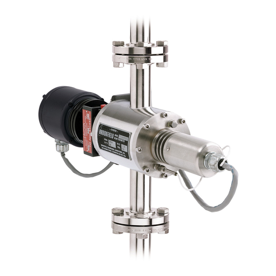
TT100 In-Line Viscometer Installation, Operation, Maintenance and Service Instructions Figure 1-1: Typical TT100 In-Line Viscometer with Oriental Motor P/N M/97-520... -
Page 12: Figure 1-2: Typical Tt100 In-Line Viscometer With Groschopp Motor
In-Line Viscometer Description CENELEC NEMA 7 Figure 1-2: Typical TT100 In-Line Viscometer with Groschopp Motor P/N M/97-520... -
Page 13: Theory Of Operation
TT100 In-Line Viscometer Installation, Operation, Maintenance and Service Instructions Theory of Operation The product stream flows through the inlet into the TT100 In-Line Viscometer measuring chamber, as shown in Figure 1-3, where it pushes against a cylinder or rotor driven by a drive motor. The rotation of the rotor causes a gentle pumping action forcing the product to flow into the measuring annulus between the rotor and the stator. -
Page 14: Correlation With Other Measurements
Many factors beyond those noted above, which are more difficult to control in an on-line situation than in a laboratory environment, can potentially affect your correlation. Refer to Appendix A and contact Brookfield Engineering Laboratories, Inc. for assistance in generating an empirical correlation. -
Page 15: Specifications
TT100 In-Line Viscometer Installation, Operation, Maintenance and Service Instructions Specifications The TT100 In-Line Viscometer is available in standard or optional configurations as listed in Table 1-1. Table 1-1: Model TT100 In-Line Viscometer Specifications Parameter Standard Configuration Optional Configuration* Viscosity Range... -
Page 16: Required Utilities
100 watts. However, the instantaneous starting current requirement for the TT100 drive motor can be at least five times greater. Brookfield Engineering Laboratories, Inc. recommends that any inverter, transformer, or similar device that is used with the Model TT100 should be rated at 750 volt-amperes or greater. P/N M/97-520... -
Page 17: Cleaning
The flushing option, available in the TT100, is offered in either or both endcaps. When in use, the cleaning fluid is introduced towards the internal components through directional spray nozzles. -
Page 18: Component Identification
In-Line Viscometer Description Component Identification The following paragraphs provide a brief description of each component within the TT100 In-Line Viscometer. Refer to Figure 1-5 for the component location within the viscometer. Torque Sensor Assembly The Torque Sensor Assembly contains the torsion element, armature, and field coil. -
Page 19: Drive Endcap
TT100 In-Line Viscometer Installation, Operation, Maintenance and Service Instructions Drive Endcap The Drive Endcap supports the rotor, mechanical seal, drive shaft, bearings and bearing housing, motor, and all related mechanical components. Motor Cable The Motor Cable supplies electrical power to the motor from the motor control enclosure, or directly from a power source. -
Page 20: Sensing Cable
Sensing Cable CAUTION Changing the length of the sensing cable will affect viscometer calibration. Refer to Appendix A and contact Brookfield Engineering Laboratories for more information. The Sensing Cable carries the electrical signal that is proportional to the viscous drag of the process fluid. The signal is sent to the torque sensor electronics enclosure for processing. -
Page 21: Motor Control Enclosure
TT100 In-Line Viscometer Installation, Operation, Maintenance and Service Instructions Motor Control Enclosure The Motor Control Enclosure accepts 115/230 VAC and supplies appropriate power to the drive motor. The enclosure also contains the motor ON/OFF power switch and optional motor speed controller for variable speed motor applications. -
Page 22: Options
Options The following optional equipment is available to enhance the operation of the TT100 In-Line Viscometer when installed within certain product stream applications. Refer to Appendix A and contact Brookfield Engineering Laboratories, Inc. for more information on these options and accessories. -
Page 23: Accessories
TT100 In-Line Viscometer Installation, Operation, Maintenance and Service Instructions Accessories The following accessories are available to display, control, and record data from the TT100 In-Line Viscometer. • Analog Display • Digital Display • Controller • Recorder • Temperature Indication •... - Page 24 In-Line Viscometer Description 1-16 P/N M/97-520...
-
Page 25: Section 2 - Installation
Installation Requirements NOTE: Refer to the TT100 In-Line Viscometer Specification sheet to determine the configuration of the viscometer. The TT100 In-Line Viscometer must be installed in a manner that will optimize its performance. The installation requirements are: • Provide a continuous product stream to the viscometer with a minimum time lag between changes in process and their effects on the viscometer. - Page 26 Provide a continuous product stream flow rate of 0.5 to 20 GPM that produces a pressure drop of less than 25 psi. NOTE: The estimated resistance to flow of a 1, 1.5, or 2 inch TT100 is equivalent to that of an average 3 inch globe valve.
-
Page 27: Calculating Minimum Straight Pipe Length
TT100 In-Line Viscometer Installation, Operation, Maintenance and Service Instructions Calculating Minimum Straight Pipe Length NOTE: The TT100 In-Line Viscometer does not require special supports or special pipe alignment. The housing is symmetrical with respect to the flow direction. Refer to Figure 2-1 and the following procedure to install the viscometer. -
Page 28: Figure 2-1: Typical In-Line Viscometer Installation
Installation ALTERNATE INSTALLATION TORQUE SENSOR ELECTRONICS ENCLOSURE 115 or 230 VAC 50 or 60 HZ 14 INCH MINIMUM CLEARANCE PREFERRED 16 INCH MINIMUM INSTALLATION CLEARANCE PIPE DIAMETER X 10 = MINIMUM STRAIGHT PIPE LENGTH MOTOR CONTROL ENCLOSURE MAIN LINE 115 or 230 VAC 50 or 60 HZ BYPASS FLOW 0.5 - 20 GPM... -
Page 29: Figure 2-2:Nema 4 - 115 Or 230 Vac 50/60 Hz Installation
TT100 In-Line Viscometer Installation, Operation, Maintenance and Service Instructions TORQUE SENSOR ELECTRONICS ENCLOSURE POWER CABLE CUSTOMER SUPPLIED 4 - 20 mA OUTPUT SIGNAL CABLE MOTOR CONTROL ENCLOSURE NOTE: REFER TO DRAWING NUMBER CA1-001 (115 VAC) OR CA1-047 (230 VAC) IN APPENDIX B FOR ELECTRICAL CONNECTIONS. -
Page 30: Figure 2-3:Nema 7 - Explosion Proof 115 Vac 50/60 Hz Installation
Installation TORQUE SENSOR NON-HAZARDOUS AREA ELECTRONICS ENCLOSURE POWER CABLE CUSTOMER SUPPLIED 4 - 20 mA OUTPUT SIGNAL CABLE HAZARDOUS (CLASSIFIED) AREA CUSTOMER SUPPLIED MOTOR POWER MOTOR CABLE CONTROL ENCLOSURE NON-HAZARDOUS AREA NOTE: REFER TO DRAWING NUMBER CA1-035 IN APPENDIX B FOR ELECTRICAL CONNECTIONS. NOTE: ALL CONNECTIONS SHALL BE TERMINATED ACCORDING TO FACTORY MUTUAL NEMA 7 SPECIFICATIONS. -
Page 31: Figure 2-4:Cenelec - 115 Or 230 Vac 50/60 Hz Installation
TT100 In-Line Viscometer Installation, Operation, Maintenance and Service Instructions NON-HAZARDOUS AREA TORQUE SENSOR ELECTRONICS ENCLOSURE POWER CABLE CUSTOMER SUPPLIED 4 - 20 mA OUTPUT SIGNAL CABLE HAZARDOUS (CLASSIFIED) AREA MOTOR CONTROL NON-HAZARDOUS AREA ENCLOSURE NOTE: REFER TO DRAWING NUMBER CA1-024 (115 VAC) OR CA1-025 (230 VAC) IN APPENDIX B FOR ELECTRICAL CONNECTIONS. -
Page 32: Flushing Connections
Installation Flushing Connections NOTE: The flushing connections and lines, which may be connected to one or both endcaps, are application specific. 1. Remove the flushing connection plug from each endcap. 2. Install the flushing line connector in the respective endcap. 3. -
Page 33: Section 3 - Calibration
TT100 In-Line Viscometer Installation, Operation, Maintenance and Service Instructions Section 3 - Calibration Introduction The TT100 In-Line Viscometer is custom calibrated at the factory and shipped ready for service. Brookfield Engineering Laboratories, Inc. recommends that certain calibration procedures be performed after any of the following events have occurred: •... -
Page 34: Tools Required
Calibration Tools Required The tools listed in Table 3-1 are required for calibrating the TT100 In-Line Viscometer. Table 3-1: Tools Required Tool Quantity Digital Volt Meter #18 - 24 AWG Insulated Wires - 6 inches long Medium Straight Blade Screwdriver... -
Page 35: Figure 3-1: Typical Installation Calibration Flowchart
TT100 In-Line Viscometer Installation, Operation, Maintenance and Service Instructions START Install Viscometer (Refer to Section 2) Perform Fine Zero Milliampere Calibration Test (Refer to Page 3-6) Perform Fine Zero Voltage Calibration (Refer to Page 3-21) Perform Coarse Zero Did the Fine Zero... -
Page 36: Figure 3-2: Typical Calibration After Viscometer Disassembly And Cleaning
Calibration START Perform Disassembly and Cleaning Procedures (Refer to Section 5) Perform Preliminary Torque Sensor Test (Refer to Page 3-8) Perform Single or Dual Range Viscometer Span Calibration (Refer to Page 3-10 or 3-14) Operate Viscometer (Refer to Section 4) NOTE: This flowchart assumes that the Microsyn housing cover has not been removed during the cleaning process. -
Page 37: Figure 3-3:Typical Calibration After Component Replacement
TT100 In-Line Viscometer Installation, Operation, Maintenance and Service Instructions START Perform Component Replacement Procedure(s) (Refer to Section 6) Perform Preliminary Torque Sensor Test (Refer to Page 3-8) Were armature and Microsyn field coil disturbed during component replacement? Perform Coarse Zero... -
Page 38: Fine Zero Milliampere Calibration Test
Calibration Fine Zero Milliampere Calibration Test The Fine Zero Milliampere Calibration Test should be performed after the viscometer has been installed and before process fluid has been introduced into the viscometer. This procedure ensures that the zero position of both the Microsyn field coil assembly and the torque sensor electronics are matched. -
Page 39: Figure 3-4:Torque Sensor Electronics Board Adjustment Component
TT100 In-Line Viscometer Installation, Operation, Maintenance and Service Instructions 11. Remove the DVM connections and wires from J1 on the circuit board. 12. Reconnect the milliampere output cable to J1 Pins 1 and 2 on the torque sensor electronics circuit board. -
Page 40: Preliminary Torque Sensor Test
Calibration Preliminary Torque Sensor Test Perform the following checks to make sure the torque sensor is not damaged before calibrating the viscometer. 1. Remove the sensing endcap from the viscometer as follows: CAUTION The internal components of the viscometer must be empty of process fluid, clean, and free of obstructions before it can be calibrated. -
Page 41: Figure 3-5: Applying Torque To The Stator
TT100 In-Line Viscometer Installation, Operation, Maintenance and Service Instructions g. Connect the DVM positive lead to the wire installed on J1-Pin 1. h. Connect the DVM negative lead to the wire installed on J1-Pin 2. i. Turn power ON to the torque sensor electronics enclosure. -
Page 42: Single Range Viscometer Span Calibration
Calibration Single Range Viscometer Span Calibration In this procedure, a calibration bar will be used to simulate torque the torsion element will encounter during single range measurement of your specific process fluid. Span calibration allows the torque sensor electronics to be adjusted for the specific range gain in milliamperes from the no torque or (zero point) set at 4.00 mA through 20.00 mA with the calibration bar applied. - Page 43 TT100 In-Line Viscometer Installation, Operation, Maintenance and Service Instructions b. While holding the sensing endcap in position, remove the last screw and carefully remove the sensing endcap from the measuring chamber. NOTE: Both the torsion element axis and the calibration bar axis must be within 8º...
-
Page 44: Figure 3-6: Calibration Bar Installation
4.00 ± .02 mA. NOTE: If steps 13 and 14 cannot be achieved, refer to Appendix A and call Brookfield Engineering Laboratories, Inc. for assistance. 16. Repeat steps 12 - 14 to ensure calibration repeatability. 17. Turn power OFF to the torque sensor electronics enclosure. - Page 45 TT100 In-Line Viscometer Installation, Operation, Maintenance and Service Instructions 19. Reconnect the milliampere cable to J1 Pins 1 and 2 on the torque sensor electronics circuit board and install the enclosure cover. CAUTION Handle the sensing endcap assembly with care when installing it into the measuring chamber.
-
Page 46: Dual Range Viscometer Span Calibration
Calibration Dual Range Viscometer Span Calibration In this procedure, calibration bars will be used to simulate a torque the torsion element will encounter during dual (high and low range) measurement of your specific process fluid. Span calibration allows the torque sensor electronics to be adjusted with the calibration bar applied for the specific range gain in milliamperes from the no torque (zero point) set at 4.00 mA through 20.00 mA. - Page 47 TT100 In-Line Viscometer Installation, Operation, Maintenance and Service Instructions 5. Perform the following steps to allow Digital Volt Meter (DVM) connections to the torque sensor printed circuit board: a. Cut two lengths of #18 - 24 AWG wire 6 inches long.
-
Page 48: Figure 3-7: Calibration Bar Installation
16. Adjust R51 for the HIGH range mA value shown on the Viscometer Specification Sheet. NOTE: If 4.00 ± .02 mA cannot be achieved in step 16, refer to Appendix A and call Brookfield Engineering Laboratories, Inc. for assistance. 17. Remove the calibration bar. The DVM should indicate 4.00 ± .02 mA. - Page 49 TT100 In-Line Viscometer Installation, Operation, Maintenance and Service Instructions 24. Turn power OFF to the torque sensor electronics enclosure. 25. Remove the DVM wire connections from the torque sensor electronics circuit board. 26. Reconnect the milliampere cable to J1 Pins 1 and 2 on the torque sensor electronics circuit board and install the enclosure cover.
-
Page 50: Coarse Zero Calibration
Calibration Coarse Zero Calibration CAUTION If the sensing endcap has been disassembled, then Coarse Zero Calibration must be checked before fine zero voltage calibration can occur. Failure to check the coarse zero calibration may cause problems with fine zero voltage calibration. If the sensing endcap has not been disas- sembled, then fine zero voltage calibration can be performed without checking the coarse zero calibration. -
Page 51: Figure 3-8: Microsyn Field Coil Assembly Rotation
TT100 In-Line Viscometer Installation, Operation, Maintenance and Service Instructions 10. Connect the DVM negative lead to the wire installed on J1-Pin 2. 11. Loosen, but do not remove the Microsyn field coil assembly mounting screws as shown in Figure 3-8. -
Page 52: Figure 3-9: Stator Direction Of Rotation
Calibration 15. Rotate the stator as shown in Figure 3-9. The DVM should increase in a positive direction. If the DVM reading does not increase in a positive direction, loosen the Microsyn field coil mounting screws and rotate the field coil to obtain the next possible 0 ± .2 VDC position. -
Page 53: Fine Zero Voltage Calibration
TT100 In-Line Viscometer Installation, Operation, Maintenance and Service Instructions Fine Zero Voltage Calibration CAUTION The internal components of the viscometer must be empty of process fluid, clean, and free of obstructions before it can be calibrated. Refer to Section 5 - Maintenance and perform the appropriate cleaning procedure for the process fluid application. - Page 54 Calibration 13. Proceed with Single or Dual Range Viscometer Span Calibration. 3-22 P/N M/97-520...
-
Page 55: Section 4 - Operation
TT100 In-Line Viscometer Installation, Operation, Maintenance and Service Instructions Section 4 - Operation Introduction Once the TT100 In-Line Viscometer has been installed as described in Section 2 - Installation and calibrated as described in Section 3 - Calibration, the viscometer is ready to be used. -
Page 56: Normal Operation Observations
Operation Normal Operation Observations The following conditions are considered to be normal while the TT100 In-Line Viscometer is operating: • The drive motor will be hot to the touch. • The TT100 In-Line Viscometer generates a continuous output signal that is proportional to the apparent viscosity of the process fluid being measured. -
Page 57: Start-Up
Damage to the double mechanical seal assembly may occur. Do not operate the TT100 In-Line Viscometer motor for more than five (5) revolutions when the measuring chamber is empty. The mechanical seals may be damaged. -
Page 58: Shutdown
Operation Shutdown CAUTION Do not allow the process fluid to dry or solidify. Damage to the TT100 In-Line Viscometer may result. 1. Shut the TT100 In-Line Viscometer OFF by performing the following steps: a. Set the POWER switch on the Torque Sensor Electronics Enclosure to the OFF position. -
Page 59: Section 5 - Maintenance
TT100 In-Line Viscometer Installation, Operation, Maintenance and Service Instructions Section 5 - Maintenance Introduction There are three different methods for cleaning the internal components of the TT100 Process Viscometer. The Clean-in-Place method, which is typically used, provides minimal downtime and effective cleansing of the viscometer during process system cleaning. -
Page 60: Flushing
Maintenance Flushing NOTE: This procedure assumes that flushing connections have been made to the TT100 Viscometer as defined in Section 2 - Installation. NOTE: The solvent used for cleaning the viscometer is dependent upon the process fluid being measured. 1. Refer to Section 4 - Operation and perform the Shutdown procedure. -
Page 61: Disassembly And Cleaning
TT100 In-Line Viscometer Installation, Operation, Maintenance and Service Instructions Disassembly and Cleaning The following procedures will guide you through this process. The solvent used for cleaning the viscometer is dependent upon the process fluid being measured. CAUTION Always replace endcap O-rings when disassembling and cleaning the vis- cometer. - Page 62 Maintenance SENSING ENDCAP ASSEMBLY O-RING STATOR MEASURING CHAMBER ROTOR O-RING DRIVE ENDCAP ASSEMBLY DRIVE SHAFT COUPLING SPACERS MOTOR BRACKET ISOLATOR DRIVE SHAFT COUPLING MOTOR/GEARBOX Figure 5-1: Typical Viscometer Disassembly for Cleaning P/N M/97-520...
- Page 63 TT100 In-Line Viscometer Installation, Operation, Maintenance and Service Instructions 4. Using an appropriate solvent, carefully clean any process fluid build-up from the outside of the stator, between the stop posts and the stator as shown in Figure 5-2, from the inside of the stator, and from the flange.
- Page 64 Maintenance STOP POST TORSION ELEMENT WIRES STATOR STATOR MOUNTING SCREWS STOP POST NOTE: There are many different versions of the sensing endcap. Your viscometer may look different from the viscometer shown in Figure 5-2. Figure 5-2: Typical Stator Removal and Torsion Element Wire Cleaning 5.
-
Page 65: Cleaning The Drive Endcap Assembly And Measuring Chamber
TT100 In-Line Viscometer Installation, Operation, Maintenance and Service Instructions STOP POSTS MOUNTING SCREWS CORRECT INCORRECT Figure 5-3: Stator Installation and Stop Post Centering NOTE: If the stop posts will not align in the center of the stator holes, remove the mounting screws and rotate the stator 180º. Install the screws and repeat step 6. -
Page 66: Reassembly
6. Clean the inside and outside diameter of the rotor. 7. Make sure the rotor spins freely and the rotor is not asymmetrical. NOTE: If the rotor does not spin freely, or is asymmetrical, refer to Appendix A and contact Brookfield Engineering Laboratories for assistance. Reassembly 1. -
Page 67: Elliptical Baffle Precautions
TT100 In-Line Viscometer Installation, Operation, Maintenance and Service Instructions 6. Turn power to the motor controller enclosure OFF. CAUTION Do not damage the torsion element when installing the drive endcap assembly into the measuring chamber. 7. Refer to Section 3 - Calibration and perform the calibration procedures shown in Figure 3-2. - Page 68 Maintenance 5-10 P/N M/97-520...
-
Page 69: Section 6 - Service
TT100 In-Line Viscometer Installation, Operation, Maintenance and Service Instructions Section 6 - Service Introduction The TT100 In-Line Viscometer is a highly-reliable and rugged unit that requires little maintenance. Section 6 provides information on component replacement. CAUTION Always replace endcap O-rings when disassembling and cleaning the vis- cometer. -
Page 70: Tools Required
Tools Required Table 6-1 provides a list of tools that are required for viscometer service. Refer to Appendix A and contact Brookfield Engineering Laboratories, Inc. for price and availability of the special tools listed in Table 6-1. Table 6-1: Tools Required... -
Page 71: Sensing Endcap Service
TT100 In-Line Viscometer Installation, Operation, Maintenance and Service Instructions Sensing Endcap Service This procedure provides instructions for disassembling the sensing endcap, identifying and replacing damaged components, and assembling the sensing endcap. Disassembly WARNING Make sure power has been turned OFF at the motor and torque sensor electronics enclosures before servicing the viscometer. - Page 72 Service Figure 6-1: Sensing Endcap Removal P/N M/97-520...
- Page 73 TT100 In-Line Viscometer Installation, Operation, Maintenance and Service Instructions RING INSULATOR MOUNTING SENSING CABLE SCREW TEFLON GASKET MICROSYN (NEMA 4 ONLY) HOUSING COVER INSULATOR (if so equipped) COVER TEFLON GASKET SCREW (NEMA 4 ONLY) READOUT WIRE FIELD COIL O-RING CONNECTORS...
- Page 74 9. Refer to Figure 6-4 and remove the armature assembly as follows: a. Using the Brookfield Engineering Laboratories, Inc. armature wrench P/N TT100-1T, hold the armature in place. b. Using a 9/32 inch wrench, loosen the armature clamping nut and remove the armature assembly.
- Page 75 TT100 In-Line Viscometer Installation, Operation, Maintenance and Service Instructions USE THE TT100-1T WRENCH TO HOLD THE HEX HEAD SCREW ARMATURE USE THE 9/32 INCH WRENCH TO LOOSEN AND TIGHTEN THE ARMATURE CLAMPING NUT. MICROSYN HOUSING Figure 6-4: Removing the Armature Clamping Nut 10.
-
Page 76: Microsyn Field Coil Replacement
Using a magnifying glass, inspect the sapphire jewel to make sure it is not cracked or chipped. If the sapphire jewel is damaged, refer to Appendix A and contact Brookfield Engineering Laboratories, Inc. for a replacement Microsyn housing assembly. -
Page 77: Torque Sensor Printed Circuit Board Replacement
TT100 In-Line Viscometer Installation, Operation, Maintenance and Service Instructions 5. Remove the wire connectors from the Microsyn field coil. 6. Remove the mounting screws, cable clamp, washers, and purple ground wire from the Microsyn field coil, as shown in Figure 6-2, and remove the Microsyn field coil from the sensing endcap. - Page 78 Service MOUNTING SCREW HOLES SHIELD PRIMARY - (RED) PRIMARY + (GREEN) GROUND - (PURPLE) SECONDARY - (BLUE) SECONDARY + (YELLOW) 1 2 3 4 1 2 3 GROUND Figure 6-5:Torque Sensor Electronics Enclosure Signal and Power Connection Locations 8. Make the following electrical connections: a.
-
Page 79: Torsion Element Replacement
TT100 In-Line Viscometer Installation, Operation, Maintenance and Service Instructions m. Remove the range jumper from the old circuit board and connect it to the same terminals on J2. 9. Refer to Figure 3-3 within Section 3 - Calibration. Torsion Element Replacement... - Page 80 Microsyn field coil. 12. Lift and remove the Microsyn field coil. 13. Using special wrench P/N TT100-1T, hold the assembly and loosen the armature assembly nut with a 9/32 inch wrench and remove the assembly from the center wire.
-
Page 81: Sensing Endcap Assembly
TT100 In-Line Viscometer Installation, Operation, Maintenance and Service Instructions 19. Remove the Teflon gasket. NOTE: Depending upon the application, the viscometer may contain none, 1, or 2 insulators. CAUTION Do not bend or damage the torsion element wire or when removing the insulators. - Page 82 Service STATOR Figure 6-7:Torsion Element and Endcap Alignment 5. Insert the mounting screws and using a hex wrench, rotate the screws into position but do not tighten them. 6. Place the insulator centering fixture (P/N TT-100-101TY) into the insulator. 7. Repeat steps 4 - 6 for each insulator. 8.
- Page 83 TT100 In-Line Viscometer Installation, Operation, Maintenance and Service Instructions 15. Set the height of the armature assembly as follows: a. Place the armature wrench P/N TT100-1T, on the armature hold the armature in place as shown in Figure 6-4. b. Using a small ruler to measure, lift the armature assembly 1/16 of an inch.
-
Page 84: Drive Endcap Service
Check the motor for unusual noises or vibrations. Turn power OFF. 7. Proceed as follows: a. If there are unusual noises or vibration, then the motor or capacitor is defective. Refer to Appendix A and contact Brookfield Engineering Laboratories for assistance. 6-16 P/N M/97-520... - Page 85 TT100 In-Line Viscometer Installation, Operation, Maintenance and Service Instructions b. When the replacement motor arrives, refer to Motor Replacement within this section. c. When the replacement capacitor arrives, refer to Capacitor Replacement within this section. d. If there are no unusual noises or vibrations, then the gearbox is defective.
- Page 86 Service SENSING ENDCAP ASSEMBLY MEASURING CHAMBER DRIVE ENDCAP ASSEMBLY WEEP HOLES DRIVE SHAFT COUPLING SPACERS MOTOR BRACKET ISOLATOR DRIVE SHAFT COUPLING MOTOR/GEARBOX Figure 6-9: Motor Bracket Removal 6-18 P/N M/97-520...
-
Page 87: Disassembly
TT100 In-Line Viscometer Installation, Operation, Maintenance and Service Instructions MOTOR BRACKET DRIVE SHAFT COUPLING GEARBOX MOTOR Figure 6-10: Motor and Gearbox Disassembly Disassembly CAUTION The drive endcap should only be disassembled if process fluid is leaking from the seals or weep holes. - Page 88 Brookfield Engineering Laboratories for a replacement seal head. 12. Check the drive shaft for scoring or damage where the wedge ring or O-ring is located. Refer to Appendix A and contact Brookfield Engineering Laboratories for a replacement drive shaft. 13. Remove the seal seat and retaining ring from the drive endcap.
- Page 89 TT100 In-Line Viscometer Installation, Operation, Maintenance and Service Instructions SENSING ENDCAP ASSEMBLY O-RING MEASURING CHAMBER O-RING DRIVE ENDCAP ASSEMBLY Figure 6-11:Drive Endcap Removal P/N M/97-520 6-21...
- Page 90 Service DRIVE SHAFT COUPLING BEARING SUPPORT MOUNTING SCREWS SNAP RING BEARING SUPPORT SNAP RING SEAL SUPPORT SEAL SEAT AND O-RING DRIVE ENDCAP SEAL HEAD DRIVE SHAFT ROTOR Figure 6-12:Drive Endcap Disassembly (with Single Mechanical Seal) 6-22 P/N M/97-520...
-
Page 91: Capacitor Replacement
TT100 In-Line Viscometer Installation, Operation, Maintenance and Service Instructions Capacitor Replacement WARNING Make sure power has been turned OFF at the motor and torque sensor electronics enclosures before replacing the capacitor. 1. Turn power OFF to the Motor and torque sensor electronics enclosure. -
Page 92: Oriental Motor Gearbox Replacement
Service Oriental Motor Gearbox Replacement 1. Remove the motor and defective gearbox and associated brack- ets from the viscometer as described in Drive Endcap Service. 2. Remove the gearbox mounting screws from the motor and separate the gearbox and motor as shown in Figure 6-10. 3. -
Page 93: Groschopp Motor Gearbox Replacement
TT100 In-Line Viscometer Installation, Operation, Maintenance and Service Instructions 8. Carefully install the gearbox on the replacement motor using the previously removed mounting screws and washers. NOTE: Do not tighten the screws. 9. Align the motor drive shaft coupling halves and install the motor on the mounting bracket. -
Page 94: Bearing Replacement
Service 9. With the gearbox mounting screws loose, adjust the position of the gearbox until the motor drive shaft coupling halves are parallel to each other. Tighten the gearbox mounting screws. NOTE: If needed, refer to the viscometer specification sheet to determine the appropriate drawing reference for step 10. - Page 95 TT100 In-Line Viscometer Installation, Operation, Maintenance and Service Instructions GROSCHOPP MOTOR HEX BOLTS SPLINE GEAR GEARBOX MOTOR MOUNTING BRACKETS DRIVE SHAFT COUPLINGS TT100 VISCOMETER Figure 6-13: Groschopp Motor and Gearbox Disassembly P/N M/97-520 6-27...
-
Page 96: Drive Endcap Assembly
Service Drive Endcap Assembly 1. Apply light oil to the wedge ring in the seal head or O-ring. 2. Compress the seal head assembly and slide the seal head onto the shaft until it bottoms out. Tighten the four set screws. 3. - Page 97 TT100 In-Line Viscometer Installation, Operation, Maintenance and Service Instructions 3. Remove the drive motor bracket mounting screws and spacers (if applicable) from the measuring chamber as shown in Figure 6-9. 4. Separate the drive shaft coupling between the measuring chamber and the drive motor.
- Page 98 Service 16. Install and tighten the mounting screws. 17. Connect the motor drive shaft to the drive endcap. 18. Install the drive motor bracket on the measuring chamber in the original position. 19. Install the drive motor bracket mounting screws and tighten. 20.
- Page 99 TT100 In-Line Viscometer Installation, Operation, Maintenance and Service Instructions DRIVE SHAFT COUPLING DOUBLE MECHANICAL SEAL MOUNTING SCREWS DOUBLE MECHANICAL SEAL ASSEMBLY O-RING DRIVE SHAFT DRIVE ENDCAP O-RING ROTOR ROTOR MOUNTING SCREWS Figure 6-14: Drive Endcap Disassembly (with Double Mechanical Seal)
- Page 100 Service 6-32 P/N M/97-520...
-
Page 101: Section 7 - Troubleshooting
The causes and corresponding actions are listed in their order of probability of occurrence. Technical Inquiries Refer to Appendix A and call Brookfield Engineering Laboratories, Inc. if you are in need of assistance. Table 7-1: Process Fluid Leaks... -
Page 102: Table 7-2:Drive Motor
Troubleshooting Table 7-2: Drive Motor Problem Possible Cause Corrective Action Motor noticeably Normal operation None hot during operation Motor will not operate, or Damaged motor or gearbox 1. Refer to Motor and must be assisted to operate Gearbox Test in Section 6. Damaged drive shaft bearings 2. -
Page 103: Table 7-3:Calibration Errors
TT100 In-Line Viscometer Installation, Operation, Maintenance and Service Instructions Table 7-3: Calibration Errors Problem Possible Cause Corrective Action No output, no change 1. No power to torque sensor 1. Make sure power is applied in output when electronics and motor control... - Page 104 Troubleshooting Table 7-3: Calibration Errors (Continued) Problem Possible Cause Corrective Action Reverse Torque 1. Coarse zero calibration 1. Refer to Coarse Zero Response incorrect. Adjustment in Section 3. 2. Reverse motor rotation. 2. Refer to Table 7-2 in Section 7. 3.
-
Page 105: Table 7-4:Correlation/Application
TT100 In-Line Viscometer Installation, Operation, Maintenance and Service Instructions Table 7-4: Correlation/Application Problem Possible Cause Corrective Action Viscometer ranging is too 1. Viscometer is empty, partially 1. Refer to Section 2 and high. Reading is consis- empty, or contains trapped air. - Page 106 Troubleshooting Table 7-4: Correlation/Application (Continued) Problem Possible Cause Corrective Action Viscometer reading continu- 1. Damaged torsion element. 1. Refer to Sensing End ously over 100% of scale. Cap Service in Section 6. 2. Solids in measuring chamber. 2. Refer to Disassembly and Cleaning in Section 5.
- Page 107 Appendix A - Customer Support Appendix A - Customer Support Introduction Use the following information to Contact Brookfield Engineering Laboratories, Inc. for technical assistance or service: Brookfield Engineering Laboratories, Inc. 11 Commerce Boulevard Middleboro, Massachusetts 02346 U.S.A. TEL: 508-946-6200 800-628-8139 (USA only - excluding MA)
- Page 108 Appendix A - Customer Support...
- Page 109 TT100 In-Line Viscometer Installation, Operation, Maintenance and Service Instructions Appendix B - Drawings TITLE DOCUMENT NO. CA1-001 WIRING DIAGRAM FOR NEMA 4 PAGE NO. CREATED BY 1 0F 1 ORIENTAL MOTOR APPROVED BY REV. NO. DATE CHK. BY 11/12/91 11/3/92...
- Page 110 Appendix B - Drawings TITLE DOCUMENT NO. CA1-035 MODEL TT100 & TT200 WIRING DIAGRAM PAGE NO. FOR 115 VAC GROSCHOPP MOTOR CREATED BY 1 OF 1 FACTORY MUTUAL APPROVED (EXPLOSION PROOF) APPROVED BY REV. NO. DATE CHK. BY 8/30/94 4/30/99...
- Page 111 TT100 In-Line Viscometer Installation, Operation, Maintenance and Service Instructions TITLE DOCUMENT NO. CA1-042 ROTARY TRANSDUCER WIRING PAGE NO. CREATED BY 1 OF 1 TT100 APPROVED BY REV. NO. DATE CHK. BY 1/7/95 5/9/96 DATE BLUE YELLOW GREEN YELLOW 1.5K GREEN...
- Page 112 Appendix B - Drawings TITLE DOCUMENT NO. CA1-047 230V WIRING DIAGRAM FOR PAGE NO. CREATED BY 1 OF 1 IP 55 GROSCHOPP MOTOR APPROVED BY REV. NO. DATE CHK. BY 12/18/97 9/9/96 DATE OPTIONAL CIRCUIT BREAKER SWITCH ASSEMBLY BROWN LIVE ON/OFF 230V/50HZ SWITCH...
- Page 113 TT100 In-Line Viscometer Installation, Operation, Maintenance and Service Instructions Figure B-5:CENELEC 115 VAC Groschopp Motor Wiring Diagram P/N M/97-520...
- Page 114 PAGE NO. CREATED BY APPROVED BY REV. NO. DATE CHK. BY DATE CONTACTOR K-M DILEM-10(230) OR EQUIVALENT RELAY ZE-0.4 (1500 RPM) RELAY ZE-0.6 (3000 RPM)-(TT100-436) REF: CA1-043 BROWN LIVE 230/50 BLUE NEUTRAL INPUT GREEN/YELLOW EARTH GROUND CAPACITOR (PER MOTOR NAMEPLATE)
- Page 115 TT100 In-Line Viscometer Installation, Operation, Maintenance and Service Instructions TITLE DOCUMENT NO. CA3-067 TT100 INLINE VISCOMETER PAGE NO. WITH 1" N.P.T. FEMALE INLET/OUTLET CREATED BY 1 0F 1 AND ORIENTAL MOTOR (NEMA 4) APPROVED BY REV. NO. DATE CHK. BY...
- Page 116 14 1/2 # OF INSULATORS DIM. NOTE: "A" 23 1/16 24 9/16 INSTRUMENT RATINGS FOR PRESSURE, TEMPERATURE & VISCOSITY "B" 8 5/16 9 13/16 REFER TO INSTRUMENT SPECIFICATION SHEET CA5-007. Figure B-8:TT100 Viscometer for Hazardous Areas (NEMA 7) P/N M/97-520...
- Page 117 TT100 In-Line Viscometer Installation, Operation, Maintenance and Service Instructions TITLE DOCUMENT NO. CA3-081 TT100 VISCOMETER WITH 1 1/2" 150 LB.INLET/OUTLET PAGE NO. FLANGES, FOR HAZARDOUS AREA APPLICATIONS CREATED BY 1 OF 1 GROSCHOPP MOTOR APPROVED BY REV. NO. DATE CHK. BY...
- Page 118 Appendix B - Drawings Figure B-10:TT100 In-Line Viscometer Double Mechanical Seal Connections B-10 P/N M/97-520...
-
Page 119: Changing Range Or Shear Rate
Depending on the application, the model TT100 viscometer can be redesigned, with minimal effort, to change the measured viscosity range and/or the shear conditions. With the design of this viscometer, the viscosity range is inversely proportional to speed, and shear rate. -
Page 120: Speed Of Rotation Change
Appendix C - Viscosity Range Change Speed of Rotation Change If only the speed of rotation is altered, the measured viscosity range changes to the proportion of: SPEED OF OLD VISCOSITY RANGE X OLD SPEED ROTATION CHANGE NEW SPEED 1000 cP x 100 RPM = 500 cP EXAMPLE: 200 RPM... -
Page 121: Torsion Element Change
TT100 In-Line Viscometer Installation, Operation, Maintenance and Service Instructions Torsion Element Change The third item which may be replaced, or have its response (calibration) altered is the torsion element or viscosity sensing device. There are four different torsion elements available, each capable of being calibrated over relatively wide limits, depending upon the sensitivity required. -
Page 122: Table C-1:Shear Rates And Factors For 2.440 Id Rotor
Appendix C - Viscosity Range Change Table C-1: Shear Rates and Factors for 2.440 ID Rotor Geometry Geometry Shear Rate Stators/RPM Factor Factor /RPM Uncoated Teflon Coated TT100-4 1.101 1.02 TT100-4B 0.504 0.476 TT100-4C 1.161 2.804 1.91 TT100-4CZ 1.161 1.916 1.88... -
Page 123: Table D-1:Agency Approvals - Tt100 In-Line Process Viscometer
TT100 In-Line Viscometer Installation, Operation, Maintenance and Service Instructions Appendix D - Agency Approvals Introduction The following agencies have given the TT100 In-Line Process Viscometer their approval for operation in the areas listed in Table D-1. Table D-1: Agency Approvals - TT100 In-Line Process Viscometer... - Page 124 Appendix D - Agency Approvals P/N M/97-520...
- Page 125 Appendix E - Warranty Information Guarantee We hereby guarantee this Brookfield Viscometer to be free from defects in workmanship and materials. If found to be defective in workmanship or materials upon being returned, within one year from the date of purchase to our factory, it will be repaired or replaced at the factory without charges.
- Page 126 Appendix E - Warranty Information P/N M/97-520...
- Page 127 Glossary Glossary Control High and Low Limits The measured values, expressed in engineering units, which cause control output to change. Centipoise/milli-pascal-seconds Units of absolute viscosity. The viscosity of water at room temperature is 1 centipoise or 1 milli-pascal-second. Correlation A relationship, usually shown as a graph, between one measurement and another.
- Page 128 Glossary Full Scale The upper limit, in engineering units, of a viscometer. For Brookfield Process Viscometers, this value must be calculated from the torque capacity, rotational speed, and the spindle design of the instrument. Laboratory Measurements Viscosity measurements made off-line by a different instrument, usually for purposes of quality control.
- Page 129 % torque being measured and also proportional to the scale. For Brookfield Process Viscometers, 4 mA = 0 cP, 12 mA = half of full scale, and 20 mA = full scale, linear between 0cP and full scale.
- Page 130 Казань +7 (843) 207-19-05 (8552) 91-01-32 Ниж.Новгород Санкт-Петербург +7 (812) 660-57-09 292-95-69 Челябинск +7 (351) Калуга +7 (4842) 33-35-03 +7 (831) 200-34-65 277-89-65 Ярославль +7 (4852) Саратов +7 (845) 239-86-35 67-02-35 сайт: brookfield.pro-solution.ru | эл. почта: bfk@pro-solution.ru телефон: 8 800 511 88 70...
- Page 131 TT100 In-Line Viscometer Installation, Operation, Maintenance and Service Instructions Index Abrasive Slurries 1-14 bench-top derived viscosity measurements 1-6 Benefits 1-1 Bleed Screw 1-11 build up 1-9 Calibration Bars 2-1, 3-2 CENELEC D-1 Cleaning 1-9 cleaning 1-1 Clean-In-Place (CIP) 1-9 Coaxial cylinder 1-1...
- Page 132 Index Fluids which harden 1-14 flushing option 1-9 Gear Box 1-11 Groschopp Motor 1-4 Hazardous area D-1 Heat Baffle 1-12 hot 4-2 inverter 1-8 Measuring Annulus 1-11 Measuring Chamber 1-11 mechanical seal 1-9, 1-11 minimum time lag 2-1 Motor Cable 1-11 Motor Control Enclosure 1-13 Motor Gearbox Lubricant 6-2 NEMA 7 D-1...
- Page 133 TT100 In-Line Viscometer Installation, Operation, Maintenance and Service Instructions Rotor 1-10 sapphire jewel 6-8 Sensing Cable 1-12 Sensing End Cap 1-10 shear rate 1-1 Solids 1-9 solids 4-2 Specifications 1-7 starting current requirement 1-8 start-up 1-1 Stator 1-10 Stop Post Centering 5-7...
- Page 134 Index P/N M/97-520...
Need help?
Do you have a question about the TT100 and is the answer not in the manual?
Questions and answers