Table of Contents
Advertisement
Quick Links
BROOKFIELD MODEL PVS RHEOMETER INSTALLATION
Архангельск +7 (8182) 45-71-35
Астрахань +7 (8512) 99-46-80
Барнаул +7 (3852) 37-96-76
Белгород +7 (4722) 20-58-80
Брянск +7 (4832) 32-17-25
Владивосток +7 (4232) 49-26-85
Волгоград +7 (8442) 45-94-42
Екатеринбург +7 (343) 302-14-75
Ижевск +7 (3412) 20-90-75
Казань +7 (843) 207-19-05
Калуга +7 (4842) 33-35-03
сайт: brookfield.pro-solution.ru | эл. почта: bfk@pro-solution.ru
AND RHEOVISION SOFTWARE
OPERATION INSTRUCTIONS
Manual No. M12-581
По вопросам продаж и поддержки обращайтесь:
Кемерово +7 (3842) 21-56-70
Киров +7 (8332) 20-58-70
Краснодар +7 (861) 238-86-59
Красноярск +7 (391) 989-82-67
Курск +7 (4712) 23-80-45
Липецк +7 (4742) 20-01-75
Магнитогорск +7 (3519) 51-02-81
Москва +7 (499) 404-24-72
Мурманск +7 (8152) 65-52-70
Наб.Челны +7 (8552) 91-01-32
Ниж.Новгород +7 (831) 200-34-65
телефон: 8 800 511 88 70
Новосибирск +7 (383) 235-95-48
Омск +7 (381) 299-16-70
Орел +7 (4862) 22-23-86
Оренбург +7 (3532) 48-64-35
Пенза +7 (8412) 23-52-98
Пермь +7 (342) 233-81-65
Ростов-на-Дону +7 (863) 309-14-65
Рязань +7 (4912) 77-61-95
Самара +7 (846) 219-28-25
Санкт-Петербург +7 (812) 660-57-09
Саратов +7 (845) 239-86-35
Сочи +7 (862) 279-22-65
Ставрополь +7 (8652) 57-76-63
Сургут +7 (3462) 77-96-35
Тверь +7 (4822) 39-50-56
Томск +7 (3822) 48-95-05
Тула +7 (4872) 44-05-30
Тюмень +7 (3452) 56-94-75
Ульяновск +7 (8422) 42-51-95
Уфа +7 (347) 258-82-65
Хабаровск +7 (421) 292-95-69
Челябинск +7 (351) 277-89-65
Ярославль +7 (4852) 67-02-35
Advertisement
Table of Contents

Related Manuals for Brookfield PVS RHEOMETER


Summary of Contents for Brookfield PVS RHEOMETER
- Page 1 BROOKFIELD MODEL PVS RHEOMETER INSTALLATION AND RHEOVISION SOFTWARE OPERATION INSTRUCTIONS Manual No. M12-581 По вопросам продаж и поддержки обращайтесь: Архангельск +7 (8182) 45-71-35 Кемерово +7 (3842) 21-56-70 Сочи +7 (862) 279-22-65 Новосибирск +7 (383) 235-95-48 Астрахань +7 (8512) 99-46-80 Киров +7 (8332) 20-58-70 Ставрополь...
-
Page 2: Table Of Contents
Contacting Brookfield Engineering Laboratories, Inc..............17 Section 2 - Installation Unpacking and Inspection ......................18 Tools Required for Installation ....................18 PVS Rheometer Installation (Without Triple Annulus) .............. 19 Bath Installation ........................19 Power Base Installation ......................19 Personal Computer Installation ..................... 21 Rheovision Software Installation .................... - Page 3 Turning Power OFF ......................23 Starting Rheovision ........................23 Baffle, Stator/Bob and Sample Cup Installation ................. 24 PVS Rheometer Installation (with Triple Annulus) ..............27 Cleaning of Wetted Parts ......................30 Torque Sensor Calibration Test ....................31 Section 4 - Rheovision Software What’s New with Rheovision ......................
- Page 4 Figure 1-3: Typical PVS Rheometer Component Identification ..........16 Figure 2-1: Rheometer Head Position and Sample Cup Height ..........20 Figure 2-2: PVS Rheometer Rear Panel Cable Connections ............21 Figure 3-1: Stator/Bob Mounting Tube Alignment (End View) ..........24 Figure 3-2: Orientation and Force Applied to Stator/Bob During Installation ......
- Page 5 Figure B-2: Location of Microsyn Wires ..................66 Tables Table 1-1: Rheovision System Requirements ................11 Table 1-2: Model PVS Rheometer Specifications ..............13 Table 1-3: Utility Requirements ....................13 Table 1-4: Geometry Sets ......................14 Table 3-1: Stator/Bob Sample Volume ..................25 Table 4-1: B.E.A.V.I.S.
- Page 6 Revisions may be issued at the time of such changes and/or deletions. Any duplication of this manual or any of its parts without expressed written permission from Brookfield Engineering Laboratories, Incorporated is strictly prohibited.
-
Page 8: Section 1 - Pvs Rheometer Description
The Brookfield Model PVS Rheometer, shown in Figures 1-1, can be used in a variety of applications where the viscosity of a fluid must be measured at temperatures which cause samples to vaporize or boil off. -
Page 9: Figure 1-1: Typical Brookfield Model Pvs Rheometer
Model PVS Rheometer Installation and Rheovision Software Operation Instructions Figure 1-1: Typical Brookfield Model PVS Rheometer Manual No. M12-581... -
Page 10: Rheovision Software
Model PVS Rheometer Installation and Rheovision Software Operation Instructions Rheovision Software Rheovision is designed for use with the Brookfield Engineering Laboratories, Inc. PVS Rheometer and Windows XP SP3, Vista and Windows 7™ computer operating systems. Its purpose is to control and collect data from the rheometer and allow it to be saved, viewed, printed, plotted, and analyzed. -
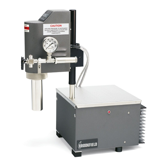
Page 11: Figure 1-2: Pvs Rheometer And Optional Bath
Model PVS Rheometer Installation and Rheovision Software Operation Instructions All electronics, bearings, and other sensitive components are completely protected from the influences of both the sample fluid and it’s vapor. The small angle of deflection (1/2º full scale) provides quick response and minimizes hysteresis and lag during speed ramping. -
Page 12: Specifications
40 lbs. (18 kg) Complete System Weight (in optional carrying case 75 lbs. (34.01 kg) without computer) Required Utilities The PVS Rheometer requires the utility connections listed in Table 1-3 to operate. Table 1-3: Utility Requirements Parameter Value Supply Voltage* 115/230 VAC... -
Page 13: Geometry Sets
Users outside of the European Union: Please dispose of this product according to your local laws. Geometry Sets The geometry sets available for use with the PVS Rheometer are listed in Table 1-4. Table 1-4: Geometry Sets Annulus Sample... -
Page 14: Sample Cup
Model PVS Rheometer Installation and Rheovision Software Operation Instructions Sample Cup The Sample Cup (outer cylinder) contains the pressurized sample fluid. The sample cup is rotated by a motor and drive assembly which causes the sample fluid to be sheared in the annular space between the cup and the stator/bob. -
Page 15: Personal Computer
The Personal Computer (PC) is used to operate the Rheovision software that controls the PVS Rheometer. The personal computer runs on Windows XP, SP3, Vista or Windows 7™ software and should only be used to operate and control the PVS Rheometer. -
Page 16: Options
Laptop Computer The optional Laptop Computer is a configured laptop personal computer which can be used to control the PVS Rheometer when portable operation is required. The Portable computer can also be used in installations where laboratory space limitations exist. -
Page 17: Section 2 - Installation
Model PVS Rheometer Installation and Rheovision Software Operation Instructions Section 2 - Installation Unpacking and Inspection NOTE: Upon receipt, inspect the case and PVS Rheometer components for shipping damage. Report any damage to the shipping company immediately. The shipping cartons should contain the following components: •... -
Page 18: Pvs Rheometer Installation (Without Triple Annulus)
PVS Rheometer head and the pressure source. 5. While supporting the PVS Rheometer head, lower the head into the bath so that the bath fluid level is approximately one inch (25.4 mm) from the knurled ring as shown in Figure 2-1. -
Page 19: Figure 2-1: Rheometer Head Position And Sample Cup Height
Computer RS-232 communications cable to the 9 pin connector or USB port. d. PVS Rheometer Head power cable e. PVS Rheometer power cord to a 120 VAC 60 Hz power source or 230 VAC if re- quired. Manual No. M12-581... -
Page 20: Personal Computer Installation
Model PVS Rheometer Installation and Rheovision Software Operation Instructions THERMOBATH POWER SWITCH MOTOR CONNECTION RTD INPUT THERMOBATH RECEPTICLE EITHER 115 OR 230 VAC (DEPENDING ON MODEL) CABLE CONNECTIONS OPTIONAL BROOKFIELD POWER INDICATION THERMOBATH, OR OTHER LIGHT EXTERNAL BATH SELECTION SWITCH... -
Page 21: Safety And Precaution Symbols
Model PVS Rheometer Installation and Rheovision Software Operation Instructions a. Using Windows Explorer, open the window of the appropriate drive then select the setup.exe file icon. The setup routine will be executed. b. Choose START from the desktop, then select RUN. Select BROWSE and locate the appropriate drive and directory that contains the setup.exe file, then select the... -
Page 22: Section 3 - Operation
Turning Power ON 1. Set the power switch on the PVS Rheometer rear panel to the ON position. 2. Refer to the Bath Operators Manual to turn power ON to the bath. 3. Refer to Starting Rheovision to initialize Rheovision. -
Page 23: Baffle, Stator/Bob And Sample Cup Installation
NOTE: Refer to Figures 3-1 and 3-2 throughout this procedure. 1. Lift and rotate the PVS Rheometer head out of and away from the bath. 2. Remove the sample cup or torsion element guard by holding the cup or guard and by rotating the locking ring. -
Page 24: Figure 3-2: Orientation And Force Applied To Stator/Bob During Installation
Model PVS Rheometer Installation and Rheovision Software Operation Instructions Instrument Facing Front Stator/Bob Indentification Etch, Must Have Front of Instrument to Install Stator/Bob Mounting Tube Stator/Bob Installed Correctly Stator/Bob Figure 3-2: Orientation and Force Applied to Stator/Bob During Installation 4. Depending upon the stator/bob being used, fill the sample cup with process fluid as specified in Table 3-1. -
Page 25: Figure 3-3: Sample Cup, Stator/Bob And Baffle Installation
7. Rotate the sample cup and visually check for run-out errors. If a run-out error is observed, remove the sample cup and repeat steps 7 and 8. 8. Lower and rotate the PVS Rheometer head into the bath. Do not exceed 1000 psi when adjusting the pressure system regulator. -
Page 26: Pvs Rheometer Installation (With Triple Annulus)
PVS Rheometer head at 0 psi. 1. Turn the three-way valve on the PVS Rheometer head to de-pressurize the head. 2. Lift and rotate the PVS Rheometer head out of and away from the bath. 3. Remove the sample cup by rotating the locking ring. -
Page 27: Figure 3-4: Stator/Bob Mounting Tube Alignment (End View)
11. Rotate the sample cup and visually check for run-out errors. If a run-out error is observed, remove the sample cup and repeat steps 10 and 11. 12. Lower and rotate the PVS Rheometer head into the bath. Do not exceed 1000 psi when adjusting the pressure system regulator. -
Page 28: Figure 3-5: Triple Annulus Installation
Model PVS Rheometer Installation and Rheovision Software Operation Instructions STATOR SKIRT AND STATOR/BOB CUP INSERT AND SAMPLE CUP SAMPLE CUP INSERT STATOR SKIRT PIN STATOR/BOB HOLE STAT OR SKIRT SAMPLE CUP INSERT PIN SAMPLE CUP STATOR/BOB HOLE STATOR SKIRT INSTALLATION... -
Page 29: Cleaning Of Wetted Parts
1. Set the power switch on the rear panel of the PVS Rheometer to the OFF position. 2. Shut off the pressure supply to the three-way valve. -
Page 30: Torque Sensor Calibration Test
NOTE: Refer to Appendix A and contact Brookfield if the stator must be disassembled for cleaning purposes. 11. If the PVS Rheometer is to be used immediately, proceed with step 12. If the PVS Rheometer is NOT to be used immediately, reinstall the shipping guard. -
Page 31: Section 4 - Rheovision Software
Model PVS Rheometer Installation and Rheovision Software Operation Instructions Section 4 - Rheovision Software Rheovision 2012 is software designed to be used with the PVS Rheometer from Brookfield Engineering Laboratories. With Rheovision, you can run tests in the PVS High Pressure, High Temperature Rheometer and display/graph the data while the test runs. -
Page 32: Getting Started
Model PVS Rheometer Installation and Rheovision Software Operation Instructions • All data and tests is saved in a database - no more dealing with filenames and folders • Define product, fluids, customer, location, BHT and other specific parameters for samples and later search data on these same fields •... -
Page 33: Setting Up Security
Model PVS Rheometer Installation and Rheovision Software Operation Instructions Setting Up Security Once you have logged in for the first time as “admin”, you can set up security for other users and create groups of users that share permissions. You can access security settings on the Main Toolbar Menu, Security/Database, Add/Edit Users buttons. -
Page 34: Figure 4-5: Groups
Model PVS Rheometer Installation and Rheovision Software Operation Instructions Figure 4-5: Groups There are three defined groups: Administrators Power Users Standard Users You can give any user membership in a group, giving that user the group’s permission. Figure 4-6: User Membership... -
Page 35: Main Navigation Panel
Model PVS Rheometer Installation and Rheovision Software Operation Instructions Main Navigation Panel The Main Navigation Panel is where most of Rheovision’s major functions are accessed. There are 4 sections in the main navigation panel: Dashboard, Favorites, Tests, and Data. Dashboard Section Functions: •... -
Page 36: Main Tool Bar
Model PVS Rheometer Installation and Rheovision Software Operation Instructions Main Toolbar Menu The Main Toolbar Menu provides access to secondary and settings functions for Rheovi- sion 2012. • When a PVS is connected, click this button to seel all parameters within the PVS memory. -
Page 37: Figure 4-9: Security/Database Tab
Rheovision 2012 that you want them to. Database - Clicking this button displays a dialog box that allows an admin- istrator to point Rheovision 2012 to a SQL database. Policies - This function is only for Brookfield Engineering factory use. • User Change Password - Click this button to display a dialog box that allows any user to change their own password. -
Page 38: Dashboard
Model PVS Rheometer Installation and Rheovision Software Operation Instructions Lip Seal Figure 4-10: Lip Seal Tab • Current Lip Seal Seal History - Click this button to display a dialog box that shows the lip seal history for the Serial Number of the PVS currently connected to Rheovision. -
Page 39: Favorites
Model PVS Rheometer Installation and Rheovision Software Operation Instructions The Dashboard allows you to perform the following tasks: • Observe the current readings for: viscosity, speed (rpm), % torque, shear stress, shear rate, sample temperature, bath temperature & setpoint and pressure. -
Page 40: Tests/Programs
Model PVS Rheometer Installation and Rheovision Software Operation Instructions This icon indicates a BEAVIS Program. Double clicking the icon will display the Test Header Parameters window then, after entering parameters and clicking the OK button, start the program. This icon indicates an empty slot where a Quick Test or BEAVIS Program can be added to the Favorites bar. -
Page 41: Quick Test Wizard
Model PVS Rheometer Installation and Rheovision Software Operation Instructions Figure 4-14: Test Head Parameters From the Data Type drop down box, you can select the appropriate category. When you do, the appropriate data shows in the list box. Below the list box is a navigation bar that allows you to move down or up the list, move to the first or last record, add or delete a record and accept a newly entered record. -
Page 42: Figure 4-16: Test Wizard Opening Screen
Model PVS Rheometer Installation and Rheovision Software Operation Instructions Figure 4-16: Opening Screen Figure 4-17: Enter Speed and Time Enter the number of speeds in the ramp. Enter the hold time at each speed in mm:ss. Enter each speed either using RPM or 1/sec. Entering one automatically calculates the other based on the Bob selected on the dashboard. -
Page 43: Figure 4-18: Enter Mix Step, Duration And Data Interval
Model PVS Rheometer Installation and Rheovision Software Operation Instructions Figure 4-18: Enter Mix Step, Duration and Data Interval This screen allows you to choose whether or not to do a Mix Step at the end of each speed ramp. If the box is checked, you need to enter: 1. -
Page 44: Figure 4-20: Choose Data Collection
Model PVS Rheometer Installation and Rheovision Software Operation Instructions 3. Do you want to wait for the sample to reach the specified temperature before running the speed ramps? If so, you can enter a speed for this period and an interval at which to collect data. -
Page 45: Quick Test List Screen
Model PVS Rheometer Installation and Rheovision Software Operation Instructions This screen allows the user to specify how many cycles (temperature equilibrium, speed ramp, mix step) should be run. The top portion indicates the time it takes for a single speed ramp and mix step (if applicable) will take to run. -
Page 46: Beavis Programs
What is a BEAVIS Program? BEAVIS (Brookfield Engineering Advanced Viscometer Instruction Set) is a command language developed at Brookfield Engineering Labs that allows control of Brookfield viscometers/rheometers and associated accessories (i.e. temperature controllers). The commands allow the creation of both simple and complex test programs that provide maximum flexibility in completely unattended data gathering. -
Page 47: Beavis Commands
Model PVS Rheometer Installation and Rheovision Software Operation Instructions Click the Build/Choose Program button to display the BEAVIS Programs window. You can specify all or part of a program name to show all programs containing that text in the Program Name box. -
Page 48: Beavis Program Screen
Model PVS Rheometer Installation and Rheovision Software Operation Instructions Command Function Description Reset Zero Zero the torque. This records the current torque reading and subtracts it from all future readings. Wait for Data Points The program remains at this step until the specified number of data points are collected from the time this command is issued. -
Page 49: Building Programs
Model PVS Rheometer Installation and Rheovision Software Operation Instructions name new programs and a label to show which program is in use. Run the Program - A program cannot be run until the Run Icon is clicked. Close the BEAVIS Program screen. -
Page 50: View Data Graphs
Model PVS Rheometer Installation and Rheovision Software Operation Instructions You can enter any part of the field you’re looking for in any combination to narrow down the number of data sets returned when the Find Data button is clicked. Clicking the Find Data button with all the search fields empty will return all the data sets in the database. -
Page 51: Communications
Model PVS Rheometer Installation and Rheovision Software Operation Instructions Communications Rheovision 2012 communicates with the PVS via either a USB connection or an RS-232 connection. On the Options toolbar, in the Communications section, there is a drop down box that shows all the ports present in the PC. -
Page 52: Section 5 - Troubleshooting
The information in Section 5 will help you troubleshoot problems when they occur. The problems presented in Table 5-1 are followed by possible causes and corrective actions listed in their order of probability of occurrence. Table 5-1: PVS Rheometer Troubleshooting Procedures (continued on next page) Problem Possible Cause... - Page 53 Brookfield for assistance. Sample cup wobbles. Loose knurled ring or sample Refer to Sample Cup, cup not installed properly on Stator/Bob Installation in hub. Section 3. Table 6-1: PVS Rheometer Troubleshooting Procedures (continued on next page) Manual No. M12-581...
-
Page 54: Communication Problems
Model PVS Rheometer Installation and Rheovision Software Operation Instructions Problem Possible Cause Corrective Action Torque hang-up (Zero Friction in the torque sensor Refer to Appendix A and point return from the posi- assembly. contact Brookfield for tive direction is different assistance. -
Page 55: Windows Xp Sp3/Vista/W7
USE FIFO BUFFERS (REQUIRES 16550 COMPATIBLE UART). 10. Select the OK buttons to accept the changes and get back to the desktop. 11. If communication problems still exist, refer to Appendix A and contact Brookfield Engineering, Inc. technical support. Manual No. M12-581... -
Page 56: Section 6 - Pvs Sensing Stack Replacement
Model PVS Rheometer Installation and Rheovision Software Operation Instructions Section 6 - PVS Sensing Stack Replacement Tools Required • (1) Medium slotted screwdriver • (1) Small slotted screwdriver • (1) Phillips head screwdriver • (1) Armature wrench (P/N TT-100-1T) •... - Page 57 Model PVS Rheometer Installation and Rheovision Software Operation Instructions 4. Remove the lip seal and retainer assembly (PVS-405HY) by removing the (4) phillips head screws. 5. Remove the O-ring (PVS-195) and backup ring (PVS-192) by applying slight pressure to the outer diameter with a small screwdriver until the other side of the ring lifts from the Drive Hub Assembly.
-
Page 58: Reassembly
Drive hub assembly (PVS-190PY). Make sure to remove the wave spring (PVS-37) and preload spacer (PVS-14) from under the sensing stack, as you will need these during the rebuilding procedure. 14. Package the old sensing stack assembly and return to Brookfield Engineering Labs, Inc. for refurbishing. Reassembly 1. - Page 59 Model PVS Rheometer Installation and Rheovision Software Operation Instructions until it contacts the jewel then pull up slightly so that the bottom of the armature will not rub on the jewel, then the nut should be tightened to the wire using the TT-100-1T wrench and 9/32 wrench so that it is secure.
- Page 60 Model PVS Rheometer Installation and Rheovision Software Operation Instructions 10. Replace one of the screws which hold the fan in place and position so that when the fan operates that the fan blades will not come into contact with anything. Reconnect the PVS head to the base and the CPU to the base.
-
Page 61: Figure 6-1: Pvs Rheometer Component Identification
Model PVS Rheometer Installation and Rheovision Software Operation Instructions PVS-196R (Cover) PVS-231 PVS-185 PVS-166 (Nameplate) (Fan 24 VDC) (Fan Guard) PVS-122 (Warning Label) PVS-187 (Motor) PVS-341 (Caution Label) PVS-245 (Timing Belt Pulley) PVS-SS-STHT (Sensing Stack, Standard Torque, High Temp) PVS-117-B... -
Page 62: Figure 6-2: Pvs Sensing Stack (Exploded View)
Model PVS Rheometer Installation and Rheovision Software Operation Instructions TT100-485 Screw, M5X25, HEX SOC Cap Head (3) PVS-204Y PVS-273 Microsyn Housing w/Jewel, PVS Shipping Tube (Short) 50S103216D140 Screw 10-32X1/2 HEX SOC HD 316SS (3) PVS-208 Insulator, Transducer PVS-TSY Torsion Element Ass’y, Standard, PVS... -
Page 63: Appendix - Customer Support
Hours of Operation • Equipment Type NOTE: Contact Brookfield to obtain a Return Material Authorization number before re- turning any equipment. The instrument must be cleaned prior to shipment and an MSDS must be provided for the materials being handled. -
Page 64: Appendix B - Drawings
Model PVS Rheometer Installation and Rheovision Software Operation Instructions Appendix B - Drawings RS-232 Cables, Part No. DVP-80 Use the information in Figure B-1 to test or to make your own RS-232 communication cable. NOTE: Your computer may use either a standard 9-pin or 25-pin (male or female) D-type connector. - Page 65 Model PVS Rheometer Installation and Rheovision Software Operation Instructions Location Of Microsyn Sensing Wires Use Figure B-2 for the correct location of the microsyn sensing wires. NOTE: The green/black and blue/black wire combinations are braided together. PIN #3 PIN #2...
-
Page 66: Appendix C - Calculations
Model PVS Rheometer Installation and Rheovision Software Operation Instructions Appendix C – Calculations Geometry (Stator) Factors Each measurement geometry is made up of a stator (sometimes referred to as a bob) and a cup with optional inserts in between the two. The purpose of having multiple geometries is to increase the measurement range of the instrument. - Page 67 Model PVS Rheometer Installation and Rheovision Software Operation Instructions Viscosity Calculation The viscosity for any rheometer model and geometry may be calculated using the equation: Viscosity [cP] = (TM * %torque * 10,000)/(rpm * SMC * SRC) Where: = Torque Multiplier...
- Page 68 Хабаровск +7 (421) 292-95-69 Санкт-Петербург +7 (812) 660-57-09 Калуга +7 (4842) 33-35-03 Ниж.Новгород +7 (831) 200-34-65 Челябинск +7 (351) 277-89-65 Саратов +7 (845) 239-86-35 Ярославль +7 (4852) 67-02-35 сайт: brookfield.pro-solution.ru | эл. почта: bfk@pro-solution.ru телефон: 8 800 511 88 70...
Need help?
Do you have a question about the PVS RHEOMETER and is the answer not in the manual?
Questions and answers