Advertisement
Quick Links
UDP C8051F960/Si1020 MCU C
U
'
G
SER
S
U ID E
1. Introduction
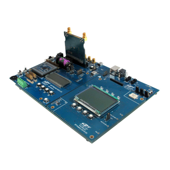
The Unified Development Platform (UDP) provides a development and demonstration platform for Silicon
Laboratories microcontrollers and the Silicon Laboratories software tools, including the Silicon Laboratories
Integrated Development Environment (IDE).
Rev. 0.2 2/14
C 8 0 5 1 F 9 6 x / S i 1 0 2 x
Figure 1. Unified Development Platform
Copyright © 2014 by Silicon Laboratories
EMIF
A R D W I T H
C8051F96x
Advertisement

Subscribe to Our Youtube Channel
Related Manuals for Silicon Laboratories C8051F960


Summary of Contents for Silicon Laboratories C8051F960
- Page 1 U ID E 1. Introduction The Unified Development Platform (UDP) provides a development and demonstration platform for Silicon Laboratories microcontrollers and the Silicon Laboratories software tools, including the Silicon Laboratories Integrated Development Environment (IDE). Figure 1. Unified Development Platform Rev. 0.2 2/14 Copyright ©...
-
Page 2: Relevant Documents
2. Relevant Documents This document provides a hardware overview for the Unified Development Platform (UDP) system UDP C8051F960/Si1020 MCU Card with EMIF. Additional information on the UDP system can be found in the documents listed in this section. 2.1. Motherboard User’s Guide The UDP Motherboard User’s Guide contains information on the motherboard features and can be found at... -
Page 3: Hardware Setup
C8051F96x/Si102x 3. Hardware Setup 3.1. Using the MCU Card Alone Refer to Figure 2 for a diagram of the hardware configuration when using the MCU card without a UDP motherboard. 1. Connect the USB Debug Adapter to the 2x5 debug connector on the MCU card with the 10-pin ribbon cable. - Page 4 C8051F96x/Si102x 3.2. Using the MCU Card with the UDP Motherboard Refer to Figure 3 for a diagram of the hardware configuration when using the MCU card with a UDP motherboard. 1. Connect the MCU card to the UDP motherboard slot. 2.
-
Page 5: Software Setup
Once Simplicity Studio is installed, the application itself can be used to install additional software and documentation components to aid in the development and evaluation process. Figure 4. Simplicity Studio The following Simplicity Studio components are required for the C8051F960 Development Kit: 8051 Products Part Support ... - Page 6 2. Click the Create new project link from the welcome screen or go to File Silicon Labs MCU Project. 3. In the Kit drop-down, select C8051F960 Development Kit, in the Part drop-down, select C8051F960, and in the SDK drop-down, select the desired SDK. Click Next. 4. Select Example and click Next.
- Page 7 C8051F96x/Si102x 4.3. Legacy 8-bit IDE Note: Using the Simplicity Studio tools with the C8051F960 Development Kit is recommended. See section 4. "Software Setup‚" on page 5 for more information. Download the 8-bit software from the website (www.silabs.com/8bit-software) or use the provided installer on the CD-ROM to install the software tools for the C8051F96x devices.
- Page 8 C8051F96x/Si102x Figure 5. Keil µVision4 IDE License Management Window 4. Click on the Get LIC via Internet... button to open the Obtaining a License IDE Code (LIC) window. 5. Press OK to open a browser window to the Keil website. If the window doesn’t open, navigate to www.keil.com/license/install.htm.
- Page 9 C8051F96x/Si102x 4.5. Silicon Labs Battery Life Estimator The Battery Life Estimator is a system design tool for battery operated devices. It allows the user to select the type of battery they are using in the system and enter the supply current profile of their application. Using this information, it performs a simulation and provides an estimated system operating time.
- Page 10 C8051F96x/Si102x Figure 7. Battery Life Estimator Discharge Profile Editor The Discharge Profile Editor allows the user to modify the profile name and description. The four text entry boxes on the left hand side of the form allow the user to specify the amount of time the system spends in each power mode.
- Page 11 C8051F96x/Si102x The wakeup frequency box calculates the period of a single iteration through the four power modes and displays the system wake up frequency. This is typically the "sample rate" in low power analog sensors. Once the battery type and discharge profile is specified, the user can click the "Simulate" button to start a new simulation.
- Page 12 5. UDP C8051F960/Si1020 MCU Card with EMIF Overview The C8051F96x MCU card enables application development on the C8051F960 MCU. The card connects to the MCU Card expansion slot on the UDP motherboard and provides complete access to the MCU resources. Each expansion board has a unique ID that can be read out of an EEPROM or MCU on the board, which enables software tools to recognize the connected hardware and automatically select the appropriate firmware image.
- Page 13 The UPPI Pico Board connector accommodates a variety of C8051F96x and Si102x/3x UPPI Pico Boards. The C8051F960 MCU and Si1020 Wireless MCU UPPI Pico Boards share a common form factor. This enables the MCU card to support a wide variety of wired and wireless applications.
- Page 14 The standard 10-pin debug header supports the Silicon Labs USB Debug Adapter. This connector provides a C2 debug connection to C8051F960/Si1020 on the UPPI Pico Board. The USB Debug Adapter supports two types of debug connections: C2 and JTAG. When using this MCU card with the Silicon Labs IDE, select C2 in the connection options dialog before connecting.
- Page 15 5.6. Pin Power Supply Select Switches The C8051F960/Si1020 MCU has two VIO pins: VIO and VIORF. These VIO pins set the logic level and drive voltage for the MCU port pins. The VIORF pin sets the level for the port pins normally supporting radio functionality: P1.5 through P2.3.
- Page 16 The PC0 and PC1 signals connect to P1.0 and P1.1 on the target MCU. These are dedicated pins for the C8051F960/Si1020 low-power pulse counter. The VIO and ground connections are also available for Form C meters. Refer to the C8051F960 data sheet for additional information about the pulse counter.
- Page 17 C8051F96x/Si102x 5.11. C8051F96x Board Default and Optional Connections The C8051F96x MCU card has many default and optional connections for use with different radios and the UDP motherboard. The default connections have shorting jumpers consisting of a 603 resistor footprint with a trace between the pads.
- Page 18 C8051F96x/Si102x Table 1. MCU Pin Functions (Continued) MCU Card Function UDP Motherboard Signal MCU Pin Default Optional Default Optional P3.2 SW3/LED3 P3.3 SW4/LED4 P3.4 RF_EBIF_NSS P4.6 ANT_A EZR_CLKIN/ EZRP2_GPIO3 P4.7 GPIO2 EZRP_RX_CLKOUT/ EZRP_GPIO2 5.11.1. P0.0 through P0.3 Pins P0.0 through P0.3 connect to the UDP SPI_LCD signals (SPI_LCD_SCK, SPI_LCD_MISO, SPI_LCD_MOSI, SPI_LCD_NSS) by default.
- Page 19 C8051F96x/Si102x 5.11.11. EZRadio GPIO Signals When using a Si1020 UPPI Pico Board, the four EZRadioPRO GPIO signals connect to the SMA connectors on the motherboard. GPIO_0 connects to EZRP_TX_DATA_IN via R20. This signal supports direct mode TX input data from an external source using the SMA connector.
- Page 20 C8051F96x/Si102x Table 2. MCU EMIF Connections (Continued) EMIF Configurations MCU Card Signal UDP Motherboard MCU Pin Non-Multiplexed Multiplexed Name Signal Name 16-bit 8-bit 16-bit 8-bit P6.3 EMIF_D3/AD3 EMIF_A3 P6.4 EMIF_D4/AD4 EMIF_A4 P6.5 EMIF_D5/AD5 EMIF_A5 P6.6 EMIF_D6/AD6 EMIF_A6 P6.7 EMIF_D7/AD7 EMIF_A7 Rev.
-
Page 21: Using The C8051F96X With The Udp Motherboard
The C8051F96x MCU card has four connectors with 100 pins each. These 400 pins are directly tied to the UDP motherboard and I/O cards. These signals are named and designed to support a wide variety of features and applications, and the UDP C8051F960/Si1020 MCU Card with EMIF card implements a subset of these connections. - Page 22 C8051F96x/Si102x 6.3. Shorting Blocks: Factory Defaults The UDP C8051F960/Si1020 MCU Card with EMIF comes from the factory with pre-installed shorting blocks on several headers. Figure 11 shows the positions of the factory default shorting blocks. Figure 11. Shorting Blocks: Factory Defaults Shorting blocks are installed on P2 to connect P0.4 to MCU_TX and P0.5 to MCU_RX.
- Page 23 C8051F96x/Si102x 7. Schematics Rev. 0.2...
- Page 24 C8051F96x/Si102x Rev. 0.2...
- Page 25 C8051F96x/Si102x Rev. 0.2...
- Page 26 C8051F96x/Si102x Rev. 0.2...
- Page 27 C8051F96x/Si102x Rev. 0.2...
- Page 28 C8051F96x/Si102x Rev. 0.2...
-
Page 29: Bill Of Materials
C8051F96x/Si102x 8. Bill of Materials Table 3. UDP C8051F960/Si1020 MCU Card with EMIF Bill of Materials Reference Part Number Source Description 24AA64T-I/MNY Microchip Technology 64KBIT I2C SERIAL FLASH, 400kHZ, 8- TDFN U4-5 SN74AVC4T245PWR Texas Instruments Quad Dual-Supply Level Shifter, TSSOP... - Page 30 C8051F96x/Si102x Table 3. UDP C8051F960/Si1020 MCU Card with EMIF Bill of Materials (Continued) Reference Part Number Source Description DS5, LED1-4 SML-LX0603IW-TR Lumex LED, RED DIFF, 635NM, SMT0603, OR Opto/Components Inc EQ, RoHS LP2989AIMM-3.3/NOPB National LDO REG, 500MA, ADJ, MSOP, RoHS...
- Page 31 C8051F96x/Si102x —MCU C PPENDIX EADER ESCRIPTIONS Table 4. UDP C8051F960/Si1020 MCU Card with EMIF H1 Pin Descriptions (J1) MCU Card Signal Name Usage USART_TX_A USART_RX_A USART_RTS_A USART_CTS_A USART_UCLK_A CAN_TX_B CAN_RX_B SPI_SCK_A Graphical LCD I/O Card SPI clock SPI_MISO_A Graphical LCD I/O Card SPI master-in, slave-out...
- Page 32 C8051F96x/Si102x Table 4. UDP C8051F960/Si1020 MCU Card with EMIF H1 Pin Descriptions (J1) (Continued) MCU Card Signal Name Usage I2SOUT_CLK_A I2SOUT_DOUT_A I2C_SDA_EZR EZRadioI2C data I2C_SCL_EZR EZRadio I2C clock TIMER_CT_A TIMER_EX_A TIMER_CT_B TIMER_EX_B UART_TX_A UART A transmit UART_RX_A UART A receive...
- Page 33 C8051F96x/Si102x Table 4. UDP C8051F960/Si1020 MCU Card with EMIF H1 Pin Descriptions (J1) (Continued) MCU Card Signal Name Usage GPIO07 LED4/SW4 GPIO08 Graphical LCD I/O Card Backlight GPIO09 GPIO10 GPIO11 GPIO12 GPIO13 GPIO14 GPIO15 PORT_MATCH0 PORT_MATCH1 WAKEUP0 WAKEUP1 EXT_INT0 EXT_INT1...
- Page 34 C8051F96x/Si102x Table 5. UDP C8051F960/Si1020 MCU Card with EMIF H2 Pin Descriptions (J2) MCU Card Signal Name Description UDPBUS_SDA_A Electronic Board ID I2C data UDPBUS_SCL_A Electronic Board ID I2C clock EPCA_ECI_MOTOR EPCA_CH0_MOTOR EPCA_CH1_MOTOR EPCA_CH2_MOTOR EPCA_CH3_MOTOR EPCA_CH4_MOTOR EPCA_CH5_MOTOR HVGPIO0 HVGPIO1 HVGPIO2...
- Page 35 C8051F96x/Si102x Table 5. UDP C8051F960/Si1020 MCU Card with EMIF H2 Pin Descriptions (J2) MCU Card Signal Name Description EMIF_A4 EMIF D4/AD4 EMIF_A3 EMIF D3/AD3 EMIF_A2 EMIF D2/AD2 EMIF_A1 EMIF D1/AD1 EMIF_A0 EMIF D0/AD0 EMIF_WRB EMIF write signal (active low) EMIF_OEB...
- Page 36 C8051F96x/Si102x Table 5. UDP C8051F960/Si1020 MCU Card with EMIF H2 Pin Descriptions (J2) MCU Card Signal Name Description LCD_SEG24_A LCD_SEG25_A LCD_SEG26_A LCD_SEG27_A LCD_SEG28_A LCD_SEG29_A LCD_SEG30_A LCD_SEG31_A LCD_SEG32_A LCD_SEG33_A LCD_SEG34_A LCD_SEG35_A LCD_SEG36_A LCD_SEG37_A LCD_SEG38_A LCD_SEG39_A LCD_COM0_A LCD_COM1_A LCD_COM2_A LCD_COM3_A LCD_COM4_A LCD_COM5_A...
- Page 37 C8051F96x/Si102x Table 6. UDP C8051F960/Si1020 MCU Card with EMIF H3 Pin Descriptions (J3) MCU Card Description Description PWR_VDD_IN PWR_VDD_IN PWR_VDD_OUT Programmable Supply from UDP to VBAT (VBAT Select set to UDP) PWR_VDD_OUT PWR_RADIO_IN VDC Output of DCDC to power 40-pin radio card...
- Page 38 C8051F96x/Si102x Table 6. UDP C8051F960/Si1020 MCU Card with EMIF H3 Pin Descriptions (J3) MCU Card Description Description EBID_NSS RF EBID SPI slave select C2_CLK_A Reset/C2 interface clock C2_DAT_A P7.0/C2 interface data C2_CLK_B C2_DAT_B C2_CLK_C C2_DAT_C C2_CLK_D C2_DAT_D C2_CLK_E C2_DAT_E JTAG_TDO_A...
- Page 39 C8051F96x/Si102x Table 6. UDP C8051F960/Si1020 MCU Card with EMIF H3 Pin Descriptions (J3) MCU Card Description Description H3_75 H3_76 H3_77 H3_78 H3_79 H3_80 H3_81 H3_82 H3_83 H3_84 H3_85 H3_86 H3_87 H3_88 H3_89 H3_90 H3_91 H3_92 H3_93 H3_94 H3_95 H3_96 H3_97...
- Page 40 C8051F96x/Si102x Table 7. UDP C8051F960/Si1020 MCU Card with EMIF H4 Pin Descriptions (J4) MCU Card Description Description C2D_TX00_A Capacitive Sensing output 0 C2D_TX01_A Capacitive Sensing output 1 C2D_TX02_A Capacitive Sensing output 2 C2D_TX03_A Capacitive Sensing output 3 C2D_TX04_A Capacitive Sensing output 4...
- Page 41 C8051F96x/Si102x Table 7. UDP C8051F960/Si1020 MCU Card with EMIF H4 Pin Descriptions (J4) (Continued) MCU Card Description Description ADC_IN1 ADC_IN2 ADC_IN3 DAC_VREF DAC voltage reference DAC_VREFGND DAC voltage reference ground DAC_OUT0 DAC_OUT1 DAC_OUT2 DAC_OUT3 IDAC_A IDAC A output IDAC_B IDAC B output...
- Page 42 C8051F96x/Si102x Table 7. UDP C8051F960/Si1020 MCU Card with EMIF H4 Pin Descriptions (J4) (Continued) MCU Card Description Description EZRP_SDN Radio card peripheral shutdown EZRP_NIRQ Radio card peripheral interrupt status EZR_NFFS EZR_SI100X_TX Radio card Si100x transmit EZR_DTO EZR_FFIT EZR_SI100X_RX Radio card Si100x receive...
- Page 43 The products must not be used within any Life Support System without the specific written consent of Silicon Laboratories. A "Life Support System" is any product or system intended to support or sustain life and/or health, which, if it fails, can be reasonably expected to result in significant personal injury or death.
Need help?
Do you have a question about the C8051F960 and is the answer not in the manual?
Questions and answers