Advertisement
Quick Links
UDP C8051F390/F370 MCU C
1. Introduction
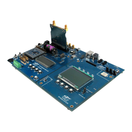
The Unified Development Platform (UDP) provides a development and demonstration platform for Silicon
Laboratories microcontrollers and the Silicon Laboratories software tools, including the Silicon Laboratories
Integrated Development Environment (IDE).
Note: The C8051F39x/F37x family has two MCU cards, one for the C8051F39x devices and one for the C8051F37x devices.
The information in this document applies to both sets of hardware, and the examples (with the exception of the
EEPROM) will run on both.
2. Relevant Documents
This document provides a hardware overview for the Unified Development Platform (UDP) system UDP
C8051F390/F370 MCU Card. Additional information on the UDP system can be found in the documents listed in
this section.
Motherboard User's Guide: The UDP Motherboard User's Guide contains information on the motherboard
features and can be found at www.silabs.com.
Card User's Guides: The UDP MCU Card and Radio Card User's Guides can be found at www.silabs.com.
Rev. 0.2 2/14
Figure 1. Unified Development Platform
Copyright © 2014 by Silicon Laboratories
C8051F39x/F37x
U
'
A R D
SER
S
G
UIDE
C8051F39x
Advertisement

Related Manuals for Silicon Laboratories UDP C8051F390


Summary of Contents for Silicon Laboratories UDP C8051F390
- Page 1 1. Introduction The Unified Development Platform (UDP) provides a development and demonstration platform for Silicon Laboratories microcontrollers and the Silicon Laboratories software tools, including the Silicon Laboratories Integrated Development Environment (IDE). Note: The C8051F39x/F37x family has two MCU cards, one for the C8051F39x devices and one for the C8051F37x devices.
-
Page 2: Hardware Setup
C8051F39x/F37x 3. Hardware Setup 3.1. Using the MCU Card Alone Refer to Figure 2 for a diagram of the hardware configuration when using the MCU card without a UDP motherboard. 1. Connect the USB Debug Adapter to the 2x5 debug connector on the MCU card with the 10-pin ribbon cable. - Page 3 C8051F39x/F37x 3.2. Using the MCU Card with the UDP Motherboard Refer to Figure 3 for a diagram of the hardware configuration when using the MCU card with a UDP motherboard. 1. Connect the MCU card to the UDP motherboard slot. 2.
-
Page 4: Software Setup
C8051F39x/F37x 4. Software Setup Simplicity Studio greatly reduces development time and complexity with Silicon Labs EFM32 and 8051 MCU products by providing a high-powered IDE, tools for hardware configuration, and links to helpful resources, all in one place. Once Simplicity Studio is installed, the application itself can be used to install additional software and documentation components to aid in the development and evaluation process. - Page 5 C8051F39x/F37x 4.1. Running Blinky Each project has its own source files, target configuration, SDK configuration, and build configurations such as the Debug and Release build configurations. The IDE can be used to manage multiple projects in a collection called a workspace.
- Page 6 C8051F39x/F37x 4.3. Legacy 8-bit IDE Note: Using the Simplicity Studio tools with the C8051F390 Development Kit is recommended. See section 4. "Software Setup‚" on page 4 for more information. Download the 8-bit software from the website (www.silabs.com/8bit-software) or use the provided installer on the CD-ROM to install the software tools for the C8051F39x devices.
- Page 7 C8051F39x/F37x www.keil.com/license/install.htm. 6. Enter the Silicon Labs Product Serial Number printed on the CD-ROM, along with any additional required information. 7. Once the form is complete, click the Submit button. An email will be sent to the provided email address with the license activation code.
- Page 8 The target MCU card can also be detached from the UDP and used alone as a development or demonstration tool. Figure 6 shows the C8051F390 MCU card. Figure 6. C8051F39x UDP MCU Card Figure 7 highlights some of the features of the UDP C8051F390/F370 MCU Card. Rev. 0.2...
- Page 9 C8051F39x/F37x 9 V Wall Adapter Connector USB Connector Debug Connector VDD Selection Switch Reset Push-Button Push-Button Potentiometer Terminal Block Figure 7. UDP C8051F390/F370 MCU Card Rev. 0.2...
- Page 10 5.2. Push-Button Switches and LEDs (SW3, D7) The UDP C8051F390/F370 MCU Card has one push-button switch. Connect to switch to port pin P1.0 by placing a shorting block on J8: SW - P1.0. The switch is normally open and pulls the pin voltage to ground when pressed.
- Page 11 C8051F39x/F37x 5.5. UART VCP Connection Options The MCU card features a USB virtual COM port (VCP) UART connection via the USB connector (P2). The VCP connection uses the CP2102 USB-to-UART bridge chip. The UART pins on the target MCU either connect to the CP2102 USB-to-UART bridge chip or to the UDP motherboard.
- Page 12 C8051F39x/F37x 5.9. C8051F39x Board Default and Optional Connections The C8051F39x MCU card has many default and optional connections for use with the UDP motherboard. The default connections have shorting jumpers consisting of a 402 resistor footprint with solder connecting the two pads.
- Page 13 C8051F39x/F37x 5.9.1. P0.2 and P0.3 By default, pins P0.2 and P0.3 connect to the EXT_INT0 and EXT_INT1 signals respectively on the UDP motherboard. To disconnect these signals, remove the solder on the R13 and R14 footprint resistors. 5.9.2. P1.1 By default, pin P1.1 connects to the CLKOUT0/SYSCLK signal on the UDP motherboard. To disconnect this signal, remove the solder on the R15 foot resistor.
- Page 14 I/O cards. These signals are named and designed to support a wide variety of features and applications, and the UDP C8051F390/F370 MCU Card card implements a subset of these connections. The MCU cards and I/O cards are designed so that a maximum number of functions are shared between each card.
- Page 15 C8051F39x/F37x 6.3. Shorting Blocks: Factory Defaults The UDP C8051F390/F370 MCU Card comes from the factory with pre-installed shorting blocks on several headers. Figure 8 shows the positions of the factory default shorting blocks. Figure 8. Shorting Blocks: Factory Defaults Shorting blocks are installed on J14 to connect P0.4 to MCU_TX and P0.5 to MCU_RX.
- Page 16 C8051F39x/F37x 7. Schematics Rev. 0.2...
- Page 17 C8051F39x/F37x Rev. 0.2...
- Page 18 C8051F39x/F37x Rev. 0.2...
- Page 19 C8051F39x/F37x Rev. 0.2...
- Page 20 C8051F39x/F37x Rev. 0.2...
- Page 21 C8051F39x/F37x Rev. 0.2...
-
Page 22: Bill Of Materials
C8051F39x/F37x 8. Bill of Materials Table 2. UPMU-F390-A/UPMU-F370-A Bill of Materials Reference Part Number Source Description C8051F390-A-GM or Silicon Labs Mixed-Signal MCU, 50 MIPS 16 kB Flash, C8501F370-A-GM 512B EEPROM, RoHS. CP2102-GM Silicon Labs SINGLE-CHIP USB TO UART BRIDGE, QFN28, RoHS. 24AA64FT-I/MNY Microchip 64KBIT I... - Page 23 C8051F39x/F37x Table 2. UPMU-F390-A/UPMU-F370-A Bill of Materials (Continued) Reference Part Number Source Description SP0503BAHTG Littelfuse Inc TVS AVAL DIODE ARRAY, 3 CH, SOT143, RoHS. J1 J6-7 J9-13 PBC02SAAN Sullens Connector STAKE HEADER, 1X2, 0.1"CTR, GOLD, OR Solutions EQ, RoHS. PBC02DAAN Sullens Connector STAKE HEADER, 2x2, 0.1"CTR, GOLD, OR Solutions...
- Page 24 C8051F39x/F37x Table 2. UPMU-F390-A/UPMU-F370-A Bill of Materials (Continued) Reference Part Number Source Description SW2-3 EVQ-PAD04M Panasonic Electronic SWITCH, LIGHT TOUCH, 130GF, 6 mm SQ, Components RoHS. SSSS820201 Alps SWITCH SLIDE, SMT, RoHS. TP1-12 NO POP NO POP TEST POINT, PC COMPACT, NO POP, OR TP42-43 EQ, RoHS.
- Page 25 C8051F39x/F37x —MCU C PPENDIX EADER ESCRIPTIONS Table 3. UDP C8051F390/F370 MCU Card H1 Pin Descriptions MCU Card Signal Name Usage USART_TX_A USART_RX_A USART_RTS_A USART_CTS_A USART_UCLK_A CAN_TX_B CAN_RX_B SPI_SCK_A SPI0 clock SPI_MISO_A SPI0 master-in, slave-out SPI_MOSI_A SPI0 master-out, slave-in SPI_NSS0_A SPI0 slave select...
- Page 26 C8051F39x/F37x Table 3. UDP C8051F390/F370 MCU Card H1 Pin Descriptions (Continued) MCU Card Signal Name Usage I2SOUT_CLK_A I2SOUT_DOUT_A I2C_SDA_EZR EZRadioPro I C data I2C_SCL_EZR EZRadioPro I C clock TIMER_CT_A Timer0 input TIMER_EX_A TIMER_CT_B Timer1 input TIMER_EX_B UART_TX_A UART A transmit...
- Page 27 C8051F39x/F37x Table 3. UDP C8051F390/F370 MCU Card H1 Pin Descriptions (Continued) MCU Card Signal Name Usage GPIO07 GPIO08 GPIO09 GPIO10 GPIO11 GPIO12 GPIO13 GPIO14 GPIO15 PORT_MATCH0 PORT_MATCH1 WAKEUP0 WAKEUP1 EXT_INT0 External interrupt 0 EXT_INT1 External interrupt 1 EXT_ADC_TRIG0 EXT_ADC_TRIG1 EXT_DAC_TRIG0...
- Page 28 C8051F39x/F37x Table 4. UDP C8051F390/F370 MCU Card H2 Pin Descriptions MCU Card Signal Name Description UDPBUS_SDA_A Electronic Board ID I C data UDPBUS_SCL_A Electronic Board ID I2C clock EPCA_ECI_MOTOR EPCA_CH0_MOTOR EPCA_CH1_MOTOR EPCA_CH2_MOTOR EPCA_CH3_MOTOR EPCA_CH4_MOTOR EPCA_CH5_MOTOR HVGPIO0 HVGPIO1 HVGPIO2 HVGPIO3 HVGPIO4...
- Page 29 C8051F39x/F37x Table 4. UDP C8051F390/F370 MCU Card H2 Pin Descriptions (Continued) MCU Card Signal Name Description EMIF_A4 EMIF_A3 EMIF_A2 EMIF_A1 EMIF_A0 EMIF_WRB EMIF_OEB EMIF_ALE EMIF_CS0B EMIF_BE1B EMIF_CS1B EMIF_BE0B LCD_SEG00_A LCD_SEG01_A LCD_SEG02_A LCD_SEG03_A LCD_SEG04_A LCD_SEG05_A LCD_SEG06_A LCD_SEG07_A LCD_SEG08_A LCD_SEG09_A LCD_SEG10_A LCD_SEG11_A...
- Page 30 C8051F39x/F37x Table 4. UDP C8051F390/F370 MCU Card H2 Pin Descriptions (Continued) MCU Card Signal Name Description LCD_SEG24_A LCD_SEG25_A LCD_SEG26_A LCD_SEG27_A LCD_SEG28_A LCD_SEG29_A LCD_SEG30_A LCD_SEG31_A LCD_SEG32_A LCD_SEG33_A LCD_SEG34_A LCD_SEG35_A LCD_SEG36_A LCD_SEG37_A LCD_SEG38_A LCD_SEG39_A LCD_COM0_A LCD_COM1_A LCD_COM2_A LCD_COM3_A LCD_COM4_A LCD_COM5_A LCD_COM6_A LCD_COM7_A...
- Page 31 C8051F39x/F37x Table 5. UDP C8051F390/F370 MCU Card H3 Pin Descriptions MCU Card Description Description PWR_VDD_IN PWR_VDD_IN PWR_VDD_OUT Programmable Supply from UDP to VDD (when VDD select switch is set to UDP) PWR_VDD_OUT PWR_RADIO_IN PWR_RADIO_IN PWR_RADIO_OUT PWR_RADIO_OUT PWR_IO_IN PWR_IO_IN PWR_IO_OUT PWR_IO_OUT...
- Page 32 C8051F39x/F37x Table 5. UDP C8051F390/F370 MCU Card H3 Pin Descriptions (Continued) MCU Card Description Description EBID_NSS C2_CLK_A Reset/C2 interface clock C2_DAT_A P2.4/C2 interface data C2_CLK_B C2_DAT_B C2_CLK_C C2_DAT_C C2_CLK_D C2_DAT_D C2_CLK_E C2_DAT_E JTAG_TDO_A JTAG_TDI_A VCP_EN Active-low enable for MCU Card VCP Bridge (default)
- Page 33 C8051F39x/F37x Table 5. UDP C8051F390/F370 MCU Card H3 Pin Descriptions (Continued) MCU Card Description Description H3_75 H3_76 H3_77 H3_78 H3_79 H3_80 H3_81 H3_82 H3_83 H3_84 H3_85 H3_86 H3_87 H3_88 H3_89 H3_90 H3_91 H3_92 H3_93 H3_94 H3_95 H3_96 H3_97 H3_98 H3_99 H3_100 Rev.
- Page 34 C8051F39x/F37x Table 6. UDP C8051F390/F370 MCU Card H4 Pin Descriptions MCU Card Description Description C2D_TX00_A C2D_TX01_A C2D_TX02_A C2D_TX03_A C2D_TX04_A C2D_TX05_A C2D_TX06_A C2D_TX07_A C2D_TX08_A C2D_TX09_A C2D_TX10_A C2D_TX11_A C2D_TX12_A C2D_TX13_A C2D_TX14_A C2D_TX15_A C2D_RX00_A C2D_RX01_A C2D_RX02_A C2D_RX03_A C2D_RX04_A C2D_RX05_A C2D_RX06_A C2D_RX07_A C2D_RX08_A C2D_RX09_A...
- Page 35 C8051F39x/F37x Table 6. UDP C8051F390/F370 MCU Card H4 Pin Descriptions (Continued) MCU Card Description Description ADC_IN1 ADC0 input 1 ADC_IN2 ADC0 input 2 ADC_IN3 ADC0 input 3 DAC_VREF DAC_VREFGND DAC_OUT0 DAC_OUT1 DAC_OUT2 DAC_OUT3 IDAC_A IDAC0 output IDAC_B IDAC1 output CP_OUT_A...
- Page 36 C8051F39x/F37x Table 6. UDP C8051F390/F370 MCU Card H4 Pin Descriptions (Continued) MCU Card Description Description EZRP_SDN EZRP_NIRQ EZR_NFFS EZR_SI100X_TX EZR_DTO EZR_FFIT EZR_SI100X_RX EZR_RESET EZR_ARSSI EZR_VDI EZR_GPIO0 EZR_GPIO1 EZR_GPIO2 EZR_GPIO3 EZR_GPIO4 H4_91 ITM_DAT0 ITM_DAT1 ITM_DAT2 ITM_DAT3 ITM_CLK H4_97 H4_98 H4_99 Rev. 0.2...
- Page 37 The products must not be used within any Life Support System without the specific written consent of Silicon Laboratories. A "Life Support System" is any product or system intended to support or sustain life and/or health, which, if it fails, can be reasonably expected to result in significant personal injury or death.
- Page 38 Mouser Electronics Authorized Distributor Click to View Pricing, Inventory, Delivery & Lifecycle Information: Silicon Laboratories UPMU-F370-A-EK UPMU-F390-A-EK...
Need help?
Do you have a question about the UDP C8051F390 and is the answer not in the manual?
Questions and answers