
Related Manuals for Henny Penny LVG-202


Summary of Contents for Henny Penny LVG-202
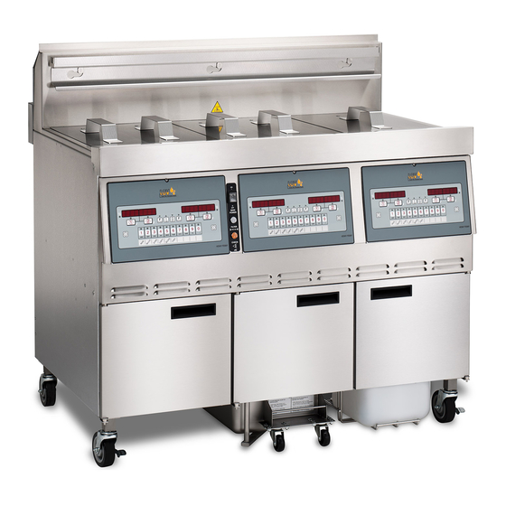
- Page 1 O O p p e e n n F F r r y y e e r r ( ( G G a a s s ) ) R R e e d d u u c c e e d d O O i i l l C C a a p p a a c c i i t t y y LVG-202 LVG-203...
-
Page 3: Table Of Contents
Table of Contents Safety......................... iii Chapter 1 Troubleshooting ....................1 1.1 Introduction ......................1 1.2 Troubleshooting Guide ...................1 1.3 Error Codes ......................5 Chapter 2 Info, Filter & Temp Button Stats.................9 2.1 Info Button Stats ....................9 2.2 Filter Button Stats ....................9 2.3 Temp Button Stats....................9 Chapter 3 Information Mode .................. - Page 4 7.6.1 Burner Tube Removal ..................40 7.6.2 Burner Tube Installation..................41 7.7 Pilot Replacement....................41 7.8 High Limit Thermocouple ..................43 7.9 High Limit Control ....................44 7.10 Probe Replacement....................45 7.11 Back Shroud Removal ..................47 7.12 Blower Replacement ..................48 7.12.1 Blower Cleaning...................48 7.12.1.1 In Housing Wheel Cleaning ...............48 7.12.1.2 Wheel Removal Cleaning................49 7.12.2 Blower Removal...................50 7.12.3 Blower Replacement ..................51...
- Page 5 S S a a f f e e t t y y The Henny Penny unit has many safety features incorporated. However, the only way to ensure safe operation is to fully understand the proper installation, operation, and maintenance procedures. The instructions in this manual have been prepared to aid you in learning the proper procedures.
- Page 6 T T e e c c h h n n i i c c a a l l D D a a t t a a F F o o r r C C E E / / A A G G A A M M a a r r k k e e d d P P r r o o d d u u c c t t s s Nominal Heat Input (Net): Natural (I ) = 19.8 KW (67,560 Btu/h)
- Page 7 Natural (I ) = 8.7 mbar Natural (I ) = N/A Natural (I ) = 8.7 mbar Natural (I ) = 8.7 mbar Liquid Propane (I ) = 25 mbar (2.5 kPa) Liquid Propane/Butane (I ) = 30/50 mbar 3B/P (3.0/5.0 kPa) Injector Size Natural (I...
-
Page 9: Troubleshooting Guide
C C h h a a p p t t e e r r 1 1 T T r r o o u u b b l l e e s s h h o o o o t t i i n n g g 1 1 . - Page 10 Problem Cause Correction Faulty gas valve. Check gas valve. Oil heating Low gas Have gas pressure checked. too slow. pressure. Wire(s) loose. Tighten wire(s). Burnt or charred Replace wire and clean connectors. wire connection. Oil over- Programming Check temperature setting in the program mode. heating.
- Page 11 Problem Cause Correction Filter Pan needs Clean filter pan and change pad. cleaned. JIB is low or Fill the JIB. empty. JIB oil line is Check JIB line. clogged or collapsed. Quick disconnect Check JIB disconnect O-ring for wear or cracking. Re- O-ring may be place if missing or torn.
- Page 12 Problem Cause Correction “IS POT All oil did not • Have manager follow prompts. FILLED” completely return prompt. after a filter cycle. • Check o-rings Filter pad Replace filter pad/clean pan. clogged. “CHECK Filter pan Find pan and install. PAN” missing.
-
Page 13: Error Codes
1 1 . . 3 3 E E r r r r o o r r C C o o d d e e s s In the event of a control system failure, the digital display shows an error message. The message codes are shown in the display column below. - Page 14 Display Cause Correction FILLED?” prompt. “E-15” Drain valve open. Clean and/or close fish vat drain valve; if cleaned and closed, have drain switch continuity checked. If no prob- lems with fish vat drain valve, check jumper on pin 15. See E-70–C. “E-18-A”...
- Page 15 Display Cause Correction “E-48” Input system Turn switch to off, then back to on; have control PC board error. replaced if “E-48” persists. “E-54C” Temperature in- Turn switch to off, then back to on; have control PC board put error. replaced if “E-54C”...
- Page 16 Display Cause Correction “E-83D” Pressure too high Have AIF system in Vat #4 checked. Vat #4 during filtering. “E-83E” Pressure too high Have AIF system in Vat #5 checked. Vat #5 during filtering. “E-83J” RTI “JIB FILL” Have JIB fill valves checked. switch on and pressure too high.
- Page 17 C C h h a a p p t t e e r r 2 2 I I n n f f o o , , F F i i l l t t e e r r & & T T e e m m p p B B u u t t t t o o n n S S t t a a t t s s NOTE: If no buttons are pressed within 5 seconds in any of stat modes, the controls revert back to normal operation.
-
Page 19: Chapter 3 Information Mode
C C h h a a p p t t e e r r 3 3 I I n n f f o o r r m m a a t t i i o o n n M M o o d d e e 3 3 . - Page 20 NOTE: Press the right arrow to view the error type. 3 3 . . 1 1 . . 2 2 L L a a s s t t L L o o a a d d Press “✓” button to select Last Load (ex: -P1- = Product 1; L1 = left, first 1 1 ) ) product) and press the up or down arrows to view the following.
- Page 21 3 3 . . 1 1 . . 5 5 I I n n p p u u t t s s H H D D E E Press the right arrow and “6. INPTS” and “HDE” show in displays. H = HIGH 1 1 ) ) LIMIT - If “H”...
-
Page 23: Modifying Product Settings
C C h h a a p p t t e e r r 4 4 L L e e v v e e l l 1 1 P P r r o o g g r r a a m m m m i i n n g g Level 1 contains the following: •... - Page 24 C C o o o o k k I I D D C C h h a a n n g g e e Press the down arrow until “COOK ID” shows in the display along with the 9 9 ) ) product ID.
- Page 25 Press “✓” button and use the left and right arrows to scroll through “ENABLE” 4 4 ) ) and “DISABLE” and then press “✓” button again to select one. If “ENABLE” is chosen, then the up and down arrows can be use to scroll 5 5 ) ) through the following list of blocking periods: M-F 1...
- Page 26 Press the down arrow 3 times and “FRYER SETUP” show in the displays. 3 3 ) ) Press “✓” button and “*SETUP* *MODE*” shows in the displays, followed by, 4 4 ) ) “LANGUAGE” on the left display, “ENGLISH” on the right display. Use the left and right arrows to change the operation display to, “FRANCAIS”, 5 5 ) ) “CAN FREN”, “ESPANOL”, “PORTUG”, “DEUTSCHE”, “SVENSKA”,...
-
Page 27: Advanced Product Settings
C C h h a a p p t t e e r r 5 5 L L e e v v e e l l 2 2 P P r r o o g g r r a a m m m m i i n n g g Used to access the following: •... - Page 28 NOTE: • Use the up arrow button to go back to previous menu items. • Press “X” button when finished with the current product, to return to the PRODUCT SELECTN step. • Press “X” button a second time to exit PROD COMP mode. 5 5 .
- Page 29 5 5 . . 4 4 A A l l e e r r t t T T o o n n e e & & V V o o l l u u m m e e Press and hold the temp and info buttons until “LEVEL - 2” shows in the display, 1 1 ) ) followed by “ENTER CODE”.
-
Page 31: Clock Set
C C h h a a p p t t e e r r 6 6 L L e e v v e e l l 3 3 P P r r o o g g r r a a m m m m i i n n g g Used to access the following: •... - Page 32 T T a a b b l l e e 6 6 - - 1 1 S S p p e e c c i i a a l l P P r r o o g g r r a a m m M M o o d d e e s s Program Code Description S S P P - - 1 1...
- Page 33 Program Code Description S S P P - - 2 2 9 9 Tmp Probe x Above Min. - XXX°F or C S S P P - - 3 3 0 0 x Above Min. Hit Limit - XXX CNT S S P P - - 3 3 1 1 Level RTD Air Cooling - X.XX°/SC S S P P - - 3 3 2 2...
- Page 34 Filter Lock Out enabled/disabled. NOTE: Not all Special Program Mode functions are discussed in this section. To ensure proper operation of fryer, please consult Henny Penny Corp. before changing any of these settings. For information on these functions, contact Service Department at 1-800-417-8405, or 1-937-456-8405.
- Page 35 Menu Step Description SP-5 Quick Press the down arrow and “SP-5 QUICK CONFIG” shows in display. Use Configuration the left and right arrows to change the menu selection in the controls to: CHKN+FSH; FF/HBR; CHKN/EMPTY. SP-6 Polish Press the down arrow and “SP-6 POLISH” shows in left display. Use Duration product buttons to change polish time, from 5 minutes to maximum of 10 minutes.
- Page 36 6 6 . . 4 4 D D a a t t a a C C o o m m m m & & H H e e a a t t C C o o n n t t r r o o l l NOTE: Data communications and heat control settings are shown in Level 3 Program Mode. To ensure proper operation of fryer, please consult Henny Penny Corp. before changing any of these settings. For more information on these functions, contact Service Department at 1-800-417-8405, or 1-937-456-8405.
- Page 37 Total Initialization. NOTE: Not all Tech Mode functions are discussed in this section. To ensure proper operation of fryer, please consult Henny Penny Corp. before changing any of these settings. For more information on these functions, contact Service Department at 1- 800-417-8405, or 1-937-456-8405.
- Page 38 Press the down arrow five times, and when display shows “F. TECH”, press the 3 3 ) ) right “✓” buttons and “T-1 SOFTWARE” shows in the display, the first step of the Tech Mode. Use the up and down arrows to toggle through the steps. NOTE: Press the right “X”...
- Page 39 Menu Step Description • “AIF X” - A problem with the communication between the PCBs. Press the down arrow and “FILR IN” “USE BY 1(ex)” shows in the dis- plays. These displays show which controls are using the filtering system. •...
- Page 40 Menu Step Description • “DIo” - RTI discard valve open. • “DIc” - RTI discard valve closed. • “JF” - JIB Fill Valve • “JFo” - RTI JIB fill valve open. • “JFc” - RTI JIB fill valve closed. Press the down button and “REQ F_J_” and “N_DI_JFo_” shows in the display.
- Page 41 Menu Step Description T-20 Pumps & Press “✓” and “VALVES” “DcRc” shows in the display. Valves • Press product 6 to open and close the drain valves. • Press product 7 to open and close the return valves. • Press product 8 to open and close the add valves. “DcRc”...
- Page 42 NOTE: Press the right “X” button twice, at any time, to return to normal operation. T T a a b b l l e e 6 6 - - 5 5 S S t t a a t t s s M M o o d d e e s s Program Code Description S S T T - - 1 1...
- Page 43 Program Code Description S S T T - - 2 2 5 5 D D Complete Cook Cycles Counted S S T T - - 2 2 6 6 Reset All Stats...
-
Page 45: Chapter 7 Maintenance
C C h h a a p p t t e e r r 7 7 M M a a i i n n t t e e n n a a n n c c e e 7 7 . . 1 1 I I n n t t r r o o d d u u c c t t i i o o n n This section provides checkout and replacement procedures for various parts of fryer. - Page 46 7 7 . . 4 4 C C o o n n t t r r o o l l P P a a n n e e l l R R e e p p l l a a c c e e m m e e n n t t Should the control panel become inoperative, or the menu card needs changed, follow these instructions.
-
Page 47: Control Panel Replacement
W W h h e e n n p p l l u u g g g g i i n n g g c c o o n n n n e e c c t t o o r r s s o o n n t t o o n n e e w w c c o o n n t t r r o o l l p p a a n n e e l l , , b b e e s s u u r r e e t t h h e e c c o o n n n n e e c c t t o o r r s s a a r r e e i i n n s s e e r r t t e e d d o o n n t t o o a a l l l l o o f f t t h h e e p p i i n n s s , , a a n n d d t t h h a a t t t t h h e e c c o o n n n n e e c c t t o o r r s s... -
Page 48: Burner Tubes
7 7 . . 6 6 B B u u r r n n e e r r T T u u b b e e s s 7 7 . . 6 6 . . 1 1 B B u u r r n n e e r r T T u u b b e e R R e e m m o o v v a a l l Remove electrical power supplied to the unit. - Page 49 7 7 . . 6 6 . . 2 2 B B u u r r n n e e r r T T u u b b e e I I n n s s t t a a l l l l a a t t i i o o n n To reassemble the burners, slide each burner tube onto the orifices.
- Page 50 While using a 1/2” wrench to hold the base of the pilot orifice, remove the two 5 5 ) ) screws securing the pilot to the burner assembly (2). The right hand screw will have the ground wire. Using a 7/16 inch wrench, loosen the pilot tube from the pilot. 6 6 ) ) Disconnect the flame sensor.
- Page 51 • To replace the flame sensor, leave pilot assembly attached to the burner assembly and remove only the flame sensor with a 7/16 inch wrench. 7 7 . . 8 8 H H i i g g h h L L i i m m i i t t T T h h e e r r m m o o c c o o u u p p l l e e Remove electrical power supplied to the unit.
- Page 52 Insert the new probe into the compression fitting. Be sure to insert the probe end 9 9 ) ) into the sleeve welded to the burner tube inside of the vat. Tighten the compression fitting nut. 1 1 0 0 ) ) 7 7 .
-
Page 53: Burner Tube Removal
Remove the clamp bars. 5 5 ) ) Slide the high limit control off of mounting studs. 6 6 ) ) Install the new control in reverse order. 7 7 ) ) 7 7 . . 1 1 0 0 P P r r o o b b e e R R e e p p l l a a c c e e m m e e n n t t S S H H O O C C K K H H A A Z Z A A R R D D T T o o a a v v o o i i d d e e l l e e c c t t r r i i c c a a l l s s h h o o c c k k , , m m o o v v e e t t h h e e p p o o w w e e r r s s w w i i t t c c h h t t o o o o f f f f a a n n d d d d i i s s c c o o n n n n e e c c t t... - Page 54 Using a terminal extractor, remove the probe terminals from the connector and 6 6 ) ) pull remove probe from unit. Place the nut and new ferrule on the new temperature probe and insert the 7 7 ) ) temperature probe into the compression fitting. See drawing below. Using the probe gauge in the kit, follow the instructions on drawing below.
- Page 55 Excess force will damage temperature probe. NOTICE Locate temperature probe through pot wall. 1 1 0 0 ) ) Place gauge against pot wall as shows in Figure 7-1 Probe Assembly Install , 1 1 1 1 ) ) page Figure 7-1 Probe Assembly Install Push temperature probe through until it makes contact with gauge.
- Page 56 7 7 . . 1 1 2 2 B B l l o o w w e e r r R R e e p p l l a a c c e e m m e e n n t t 7 7 .
- Page 57 7 7 . . 1 1 2 2 . . 1 1 . . 2 2 W W h h e e e e l l R R e e m m o o v v a a l l C C l l e e a a n n i i n n g g Loosen set screw using a hex-key.
- Page 58 File down the burr on the shaft left by the set screw, to allow wheel to slide onto 5 5 ) ) shaft freely. Install wheel with hub set to end of shaft and tighten set screw. 6 6 ) ) Turn on blower and verify that pressure is 1.7 inwc at 60 Hz (1.4 inwc at 50 Hz) 7 7 ) ) or greater.
- Page 59 Cut zip ties that are holding the wires to the blower. Remove wirenuts from the 4 4 ) ) wires. Remove blower (refer to 7.12.3 Blower Replacement , page 51). 5 5 ) ) Reconnect new blower wires to the existing wires with wirenuts. 6 6 ) ) Tighten the new blower onto the flue with the two screws.
- Page 60 S S H H O O C C K K H H A A Z Z A A R R D D T T o o a a v v o o i i d d e e l l e e c c t t r r i i c c a a l l s s h h o o c c k k , , m m o o v v e e t t h h e e p p o o w w e e r r s s w w i i t t c c h h...
- Page 61 Using an adjustable wrench, remove the flex line from the elbow. 4 4 ) ) Loosen the hose clamp with a flat blade screwdriver and disconnect the hose. 5 5 ) ) Use a 3/8 socket or wrench and remove the four nuts and washers from the 6 6 ) ) pump’s feet.
- Page 62 7 7 . . 1 1 5 5 S S e e l l e e c c t t o o r r V V a a l l v v e e D D r r i i v v e e M M o o t t o o r r R R e e p p l l a a c c e e m m e e n n t t Remove electrical power supplied to the unit.
- Page 63 Using a 5/32 Allen wrench (recommended T-handle), remove the two diagonal 8 8 ) ) screws circled below. Remove the shield. 9 9 ) ) Remove the remaining two screws. 1 1 0 0 ) ) Using a 5/32 Allen wrench (recommended T-handle), loosen the four screws on 1 1 1 1 ) ) the coupler that is clamped onto the drive tube.
- Page 64 Move to the front of the fryer and locate port 10 (1 1 ) on the selector valve body 1 1 3 3 ) ) (2 2 ). This will be the port located in the JIB area. Using an adjustable wrench, remove the flex line from port 10. 1 1 4 4 ) ) Remove the fitting and set aside.
- Page 65 Place the new motor assembly (5 5 ) onto the selector valve mounting plate (6 6 ). 1 1 7 7 ) ) Attach motor encoder assembly to selector valve body by partially threading the 1 1 8 8 ) ) four hex key screws (7 7 ) .
- Page 66 With the coupler tightened to the correct specs, run a calibration to confirm all 2 2 4 4 ) ) ports are properly aligned. See 7.15.1 Calibrate Selector Valve , page Install fitting back to selector valve and tighten. Then tighten the flex line. 2 2 5 5 ) ) Install the shield and plate to the selector valve assembly.
- Page 67 Use an adjustable wrench to remove the flex line from the back of the gas valve 4 4 ) ) that is leading to the gas manifold. Mark the locations of the wires on the gas valve and then remove the wires. 5 5 ) ) Use a 3/8 inch wrench or socket to remove the three nuts located on the bottom 6 6 ) )
- Page 68 Use a crosshead screwdriver to remove the four screws that secure the 1 1 0 0 ) ) mounting bracket onto the valve. Install the new gas valve in reverse order. 1 1 1 1 ) )
- Page 69 7 7 . . 1 1 7 7 R R e e p p l l a a c c i i n n g g t t h h e e G G a a s s V V a a l l v v e e S S o o l l e e n n o o i i d d C C o o i i l l Prior to replacing the solenoid coil, perform the gas valve troubleshooting.
- Page 70 Place new solenoid coil on gas valve stem. 8 8 ) ) Align e-clip on solenoid coil and apply pressure to snap into place. 9 9 ) ) NOTE: You may need to apply pressure with a tool such as a flat blade screwdriver. 7 7 .
- Page 71 7 7 . . 1 1 9 9 C C l l e e a a n n i i n n g g t t h h e e F F i i l l t t e e r r P P u u m m p p To remove debris from pump: Loosen four Allen head screws on the end of pump and remove cover.
- Page 72 NOTICE — A small amount of grease might be needed to hold the bottom roller into place until cover plate is put on. Make sure O-ring is in proper position on plate. I I n n d d i i c c a a t t o o r r s s , , o o n n t t h h e e s s i i d d e e o o f f t t h h e e t t w w o o h h a a l l v v e e s s o o f f t t h h e e p p u u m m p p , , m m u u s s t t a a l l i i g g n n t t o o g g e e t t h h e e r r .
- Page 73 Using a 1” wrench, loosen the rear pump fitting. 3 3 ) ) Locate the appropriate conduit on right side of the unit and disconnect the 4 4 ) ) conduit from the fryer. Using a 1/2 in. wrench, remove 4 bolts securing motor to motor bracket and pull 5 5 ) ) pump and motor assembly from fryer.
- Page 74 7 7 . . 2 2 1 1 R R e e p p l l a a c c i i n n g g t t h h e e H H u u b b m m o o u u n n t t e e d d F F i i l l t t e e r r P P u u m m p p a a n n d d M M o o t t o o r r A A s s s s e e m m b b l l y y T T h h e e f f o o l l l l o o w w i i n n g g p p r r o o c c e e d d u u r r e e o o n n l l y y a a p p p p l l i i e e s s t t o o u u n n i i t t s s w w i i t t h h s s e e r r i i a a l l n n u u m m b b e e r r s s a a f f t t e e r r t t o o...
- Page 75 Using a bungee cord, secure the ignition box out of the way. 8 8 ) ) Open the motor access panel. 9 9 ) ) Remove the M1 and M2 terminal connectors and unscrew the conduit 1 1 0 0 ) ) connector.
- Page 76 Reach around the module box housing and remove the last 7/16” bolt from the 1 1 3 3 ) ) motor bracket. Remove the hubmounted filter pump and motor assembly. 1 1 4 4 ) ) 7 7 . . 2 2 1 1 . . 2 2 I I n n s s t t a a l l l l i i n n g g t t h h e e H H u u b b m m o o u u n n t t e e d d F F i i l l t t e e r r P P u u m m p p a a n n d d M M o o t t o o r r A A s s s s e e m m b b l l y y Place the hubmounted filter pump and motor assembly on the motor bracket 1 1 ) )
- Page 77 8 8 . . 2 2 G G e e n n u u i i n n e e P P a a r r t t s s Use only genuine Henny Penny parts in your fryer. Using part of lesser quality or substitute design may result in damage to the unit or personal injury.
- Page 78 • B - Parts to be stocked at the distributor/KES location. Inventory on all other parts not identified, should be based upon usage in the territory. Please use care when ordering recommended parts, because all voltages and variations are marked. Distributors should order parts based upn common voltages and equipment sold in their territory.
-
Page 79: High Limit Control
Item Description Qty. Code Part No. TS22-012 TRANSFORMER - AIF 140296 KIT - SPARK IGNITOR (PILOT) ASSY 2/VAT 140297 KIT- SPARK IGNITOR (PILOT) ASSY LP 89624-001 HIGH LIMIT CONTROL - 120V 1/VAT 89624-002 HIGH LIMIT CONTROL - 230V 1/VAT 84391 ASSY - 75VA TRANSFORMER (120V - 1/VAT PRI / 24V - SEC) - Page 80 Figure 8-2 Burner Assembly T T a a b b l l e e 8 8 - - 1 1 B B u u r r n n e e r r P P a a r r t t s s Description Full or Burner...
- Page 81 Description Burner Altitude Full or Stock Item No. Part No. Orifice Type Split Level Drill Size Full 77941– 1/VAT (0.0935) Full 77941– I2E+ 1/VAT (0.067) Full 77941– 2.30MM 1/VAT (0.0906) Full 77941– 1.25MM I3B/P 1/VAT (0.0492) Full 77941– 1.25MM LP MIX 1/VAT (0.0492) Full...
- Page 82 Description Burner Altitude Full or Stock Item No. Part No. Orifice Type Split Level Drill Size Split 77942– 2.30MM 1/VAT (0.0906) Split 77942– 1.25MM I3B/P 1/VAT (0.0492) Split 77942– 1.25MM LP MIX 1/VAT (0.0492) Split 77942– 1.90MM 1/VAT (0.0768) Split 77942–...
- Page 83 Figure 8-3 CE Gas Valve Assembly Figure 8-4 Non-CE Gas Valve Assembly...
- Page 84 Item Description Qty. Code Part No. FP01-242 FITTING - 1/2 NPT M TO 45 FLARE M 87663-101 ASSY- GAS CONTROL VALVE- NAT - 1/VAT FULL 87663-102 ASSY- GAS CONTROL VALVE- NAT - 1/VAT SPLIT 87663-103 ASSY- GAS CONTROL VALVE- LP - 1/VAT FULL 87663-104...
- Page 85 Figure 8-5 Controls, Indicators & Body Item Description Qty. Code Part No. 52224 SWITCH - POWER 75860 LIGHT - INDICATOR - BLUE 75859 LIGHT - INDICATOR - YELLOW - - - - - ASSY - DOOR (SEE Figure 8-6 LVG-20X Door Assembly , page 77575 CASTER - 4 IN W/ BRAKE...
- Page 86 Item Description Qty. Code Part No. 03647 COVER - SPLIT VAT 77103 DECAL - FLTR - CK JIB - MAIN POWER 11 * 03646 COVER - FULL VAT 12 * 77842 HANGER - BASKET - LVG - 102 12 * 77709 HANGER - BASKET - LVG - 103 12 *...
- Page 88 Figure 8-6 LVG-20X Door Assembly Item Description Qty. Code Part No. SC04-001 SCREW - #8-32 X 3/8 PH TYPE F C 83904 STUD ASSY - DOOR HINGE - RH 83903 STUD ASSY - DOOR HINGE - LH SC04-003 SCREW - #8-32 X 3/8 PH HPD S 41836 HANDLE - DOOR...
- Page 89 Figure 8-7 Control Panel Assembly Item Description Qty. Code Part No. 97319 ASSY - CONTROL - LOV 85378 - DECAL - LOV MCD 1/CTRL NS02-005 - NUT - HEX KEPS #6 - 32 C CTRL 26974 - ASSY - SPEAKER 1/CTRL 83498 - STUD ASSY - CONTROL PANEL...
- Page 90 Figure 8-8 AIF Electronics Control Box Item Description Qty. Code Part No. ME90-008 RELAY - PUMP MOTOR - 12 VDC - 30 AMP 85698 PC BOARD - AIF 79213 TRANSDUCER - PRESSURE 30 PSI 82914 ASSY - EMC FILTER BOARD - CE 80373 BLOCK - TERMINAL POWER - CE Recommended Parts: A = Truck Stock / B = Dist.
- Page 91 Figure 8-9 Pumps Item Description Qty. Code Part No. 153417–001 PUMP - OIL TOP OFF - 120V 153471–002 PUMP - OIL TOP OFF - 230V 67583 MOTOR - 1/2 HP - 50/60 HZ (LOCATED BEHIND MOTOR) (SEE Figure 8-10 Filter Motor &...
- Page 92 Item Description Qty. Code Part No. 13 * 80728 FILTER - EMI (230V UNITS ONLY) 14 * 151686-001 HOSE - OIL DISPOSAL 140272 KIT - LVG200 PUMP PRIME 97599 SVC PACK-LV/EE JIB RETRO-115V 97600 SVC PACK-LV/EE JIB RETRO-230V Recommended Parts: A = Truck Stock / B = Dist. Stock * = Not Shown / A/R = As Requested...
- Page 93 Figure 8-10 Filter Motor & Pump Item Description Qty. Code Part No. 67583 MOTOR - 1/2 HP - 60 HZ 92850 MOTOR - 1/2 HP FILTER PUMP 50HZ 17476 SEAL KIT 171168 PUMP ASSEMBLY SC01-132 - SCREW - PUMP COVER 171171 - COVER - PUMP 171170...
- Page 94 Item Description Qty. Code Part No. SC01-026 SCREW - PUMP SHIELD 17456 SHIELD - PUMP 12 * 151534–001 ASSY - FILTER PMP & 1/2 HP MOTOR 60 HZ 12 * 151534–002 ASSY - FILTER PMP & 1/2 HP MOTOR 50 HZ Recommended Parts: A = Truck Stock / B = Dist.
- Page 95 Figure 8-11 Hubmounted Filter Pump Motor Assembly Stock Item Part No. Description Qty. Level 164184–001 MOTOR, 1/2 HP — 60 Hz — Applies to serial num- bers after BH1810136 164184–002 MOTOR, 1/2 HP — 50 Hz — CE — Applies to seri- al numbers after BH1810049 164323 PUMP ASSEMBLY, 5 GPM HUBMOUNTED...
- Page 96 Figure 8-12 Ignition Module Item Description Qty. Code Part No. 77839 MODULE - IGNITION NON CE 2/WELL 77602 MODULE - IGNITION CE 2/WELL - - - - - Figure 8-13 2-Well Gas Piping & Manifold , page 89 Figure 8-14 3 & 4- Well Gas Piping &...
- Page 97 Figure 8-13 2-Well Gas Piping & Manifold Item Description Qty. Code Part No. FP02-047 NIPPLE - 1/2 X 4 1/2 LONG FP01-090 ELBOW - 1/2 X 90 FEMALE FP01-023 NIPPLE - 1/2 INCH CLOSE...
- Page 98 Item Description Qty. Code Part No. FP01-150 UNION - 1/2 THREADED FP01-018 1/2 STR PIPE COUPLING FP02-071 FITTING - 1/2 BARB - F 1/2 NPT BRASS FP01-112 1/2 NPT FEMALE PIPE TEE FP01-078 REDUCER 3/4 MALE TO 1/2 FEMALE FP01-100 ELBOW - STREET 3/4 NPT FP01-098 ELBOW - 3/4 NPT X 90 FEMALE...
- Page 99 Figure 8-14 3 & 4-Well Gas Piping & Manifold Item Description Qty. Code Part No. FP01-100 ELBOW - 3/4 NPT FP02-044 NIPPLE - 3/4 X 2 LG FP01-141 UNION - 3/4 3000LB FP01-098 ELBOW - 3/4 NPT X 90 FEMALE FP01-032 NIPPLE - 3/4 NPT X 17 IN LONG FP02-227...
- Page 100 Figure 8-15 Flexible Gas Line Item Description Qty. Code Part No. 79327 FLEXIBLE GAS LINE W/ SHUT-OFF VALVE - 2 - WELL - 36 IN 77668-002 FLEXIBLE GAS LINE W/ SHUT-OFF VALVE - 3 - WELL - 72 IN...
- Page 101 03750 03755 03752 03756...
- Page 102 03753 03758 Item Description Qty. Code Part No. 03750 ASSY - 1/2DIA X 48LG GAS L INSTL 03752 ASSY - 3/4DIA X 36LG GAS L INSTL 03753 ASSY - 3/4DIA X 38LG GAS L INSTL 03755 ASSY - 1DIA X 72LG GAS L INSTL 03756 ASSY - 1DIA X 33LG GAS L INSTL 03758...
- Page 103 Figure 8-16 Rear of Fryer Fig. / Item Description Qty. Part No. Code 77992 SWITCH - PRESSURE - 0.80 (BEHIND 1/FULL COVERS) (before BU1806051) 2/SPLIT 92963-001 MOTOR - BLOWER - 115V (before 1/VAT BU1806051) Recommended Parts: A = Truck Stock / B = Dist. Stock * = Not Shown...
- Page 104 8-2 Tube Pressure Switches , page 89405 SELECTOR VALVE 92627 ASSY - SEL VAL MOTOR ENCODER (SEE Table 8-3 LVG-202 Flex Hose Parts , page Table 8-4 LVG-203 Flex Hose Parts , page 98, OR Table 8-5 LVG-204 Flex Hose Parts , page...
- Page 105 T T a a b b l l e e 8 8 - - 2 2 T T u u b b e e P P r r e e s s s s u u r r e e S S w w i i t t c c h h e e s s Part No.
- Page 106 T T a a b b l l e e 8 8 - - 3 3 L L V V G G - - 2 2 0 0 2 2 F F l l e e x x H H o o s s e e P P a a r r t t s s Selector Valve SD SR SS FD FR FS...
- Page 107 Selector SSD SSR FSD FSR FFD FFR Valve Port 1 1 0 0 ( ( B B U U L L K K 36 inches 36 inches 36 inches 36 inches 36 inches 36 inches D D i i s s c c a a r r d d O O i i l l ) ) B B u u l l k k N N e e w w 30 inches...
- Page 108 Selec- FFFF SSSD FSSD FFSD FFFD SSSF SSFF SFFF SSSR FSSR FFSR FFFR Valve SSSS FSSS FFSS FFFS Port B B u u l l k k N N e e w w inches inches inches inches inches inches inches inches O O i i l l N N e e w w...
- Page 109 Figure 8-18 Selector Valve Assembly Fig. / Item Description Qty. Part No. Code FP01-235 FTG - SAE ELBOW 45 DEG FLARE FP01-205 ELBOW - 1/2 IN NPT MALE 45 FLARE FP01-277 CONNECTOR - 6 SAE M 6 SAE F 90506-001 VALVE - CHECK SAE 12 3 PSI 152165 ASSY - CHK VALVE PLUMBING (SN:...
- Page 110 Figure 8-19 Vat Components Fig. / Item Description Qty. Part No. Code 76980 RACK - SPLIT VAT 1/VAT 76982 RACK - FULL VAT 1/VAT 92717 THERMOCOUPLE - HIGH LIMIT 1/VAT 140098 KIT - LVX20X/EEG16X-2XX 2.5" PRB 140206 KIT - REPLACEMENT FULL POT ASSY 140207 KIT - REPLACEMENT SPLIT POT ASSY 140208...
- Page 111 Figure 8-20 JIB Connection Fig. / Item Qty. Description Part No. Code 03617 ACCESSORY - JIB - AUTO TOP OFF (EMPTY) 85738 ASSY - JIB TUBE & QUICK DISC (INCLUDES ITEM NO 3 & 4) 85737 ASSY - INT’L JIB TUBE & QUICK DISC (IN- CLUDES ITEM NO 3 &...
- Page 112 91185 ASSY - DRAIN PAN - LVG Before 1/17 97843 ASSY - DRAIN PAN - LVG After 1/17 Recommended Parts: A = Truck Stock / B = Dist. Stock * = Not Shown / = Not Supplied By Henny Penny...
- Page 113 — O-RING - PICKUP TUBE 12126 BRUSH - BLACK L 12112 BRUSH - STRAIGHT WHITE 12116 BRUSH - FRYER - LONG HANDLE Recommended Parts: A = Truck Stock / B = Dist. Stock * = Not Shown / = Not Supplied By Henny Penny...
- Page 114 Figure 8-22 Fry Cap Fig. / Item Description Qty. Part No. Code 03702 ACCESSORY - FRY CAP - LVG-202 03703 ACCESSORY - FRY CAP - LVG-203 03704 ACCESSORY - FRY CAP - LVG-204...
-
Page 115: Prices
9 9 . . 2 2 G G e e n n u u i i n n e e P P a a r r t t s s Use only genuine Henny Penny parts in your fryer. Using part of lesser quality or substitute design may result in damage to the unit or personal injury. - Page 116 • B - Parts to be stocked at the distributor/KES location. Inventory on all other parts not identified, should be based upon usage in the territory. Please use care when ordering recommended parts, because all voltages and variations are marked. Distributors should order parts based upn common voltages and equipment sold in their territory.
- Page 117 Item Description Qty. Code Part No. TS22-012 TRANSFORMER - AIF 140296 KIT - SPARK IGNITOR (PILOT) ASSY 2/VAT 140297 KIT- SPARK IGNITOR (PILOT) ASSY LP 89624-001 HIGH LIMIT CONTROL - 120V 1/VAT 89624-002 HIGH LIMIT CONTROL - 230V 1/VAT 84391 ASSY - 75VA TRANSFORMER (120V - 1/VAT PRI / 24V - SEC)
- Page 118 Figure 9-2 Burner Assembly T T a a b b l l e e 9 9 - - 1 1 B B u u r r n n e e r r P P a a r r t t s s Description Full or Burner...
- Page 119 Description Burner Altitude Full or Stock Item No. Part No. Orifice Type Split Level Drill Size Full 77941– 1/VAT (0.0935) Full 77941– I2E+ 1/VAT (0.067) Full 77941– 2.30MM 1/VAT (0.0906) Full 77941– 1.25MM I3B/P 1/VAT (0.0492) Full 77941– 1.25MM LP MIX 1/VAT (0.0492) Full...
- Page 120 Description Burner Altitude Full or Stock Item No. Part No. Orifice Type Split Level Drill Size Split 77942– 2.30MM 1/VAT (0.0906) Split 77942– 1.25MM I3B/P 1/VAT (0.0492) Split 77942– 1.25MM LP MIX 1/VAT (0.0492) Split 77942– 1.90MM 1/VAT (0.0768) Split 77942–...
- Page 121 Figure 9-3 CE Gas Valve Assembly Figure 9-4 Non-CE Gas Valve Assembly...
- Page 122 Item Description Qty. Code Part No. FP01-242 FITTING - 1/2 NPT M TO 45 FLARE M 87663-101 ASSY- GAS CONTROL VALVE- NAT - 1/VAT FULL 87663-102 ASSY- GAS CONTROL VALVE- NAT - 1/VAT SPLIT 87663-103 ASSY- GAS CONTROL VALVE- LP - 1/VAT FULL 87663-104...
- Page 123 Figure 9-5 Controls, Indicators & Body Item Description Qty. Code Part No. 52224 SWITCH - POWER 75860 LIGHT - INDICATOR - BLUE 75859 LIGHT - INDICATOR - YELLOW - - - - - ASSY - DOOR (SEE Figure 8-6 LVG-20X Door Assembly , page 77575 CASTER - 4 IN W/ BRAKE...
- Page 124 Item Description Qty. Code Part No. 03647 COVER - SPLIT VAT 77103 DECAL - FLTR - CK JIB - MAIN POWER 11 * 03646 COVER - FULL VAT 12 * 77842 HANGER - BASKET - LVG - 102 12 * 77709 HANGER - BASKET - LVG - 103 12 *...
- Page 126 Figure 9-6 LVG-20X Door Assembly Item Description Qty. Code Part No. SC04-001 SCREW - #8-32 X 3/8 PH TYPE F C 83904 STUD ASSY - DOOR HINGE - RH 83903 STUD ASSY - DOOR HINGE - LH SC04-003 SCREW - #8-32 X 3/8 PH HPD S 41836 HANDLE - DOOR...
- Page 127 Figure 9-7 Control Panel Assembly Item Description Qty. Code Part No. 97319 ASSY - CONTROL - LOV 85378 - DECAL - LOV MCD 1/CTRL NS02-005 - NUT - HEX KEPS #6 - 32 C CTRL 26974 - ASSY - SPEAKER 1/CTRL 83498 - STUD ASSY - CONTROL PANEL...
- Page 128 Figure 9-8 AIF Electronics Control Box Item Description Qty. Code Part No. ME90-008 RELAY - PUMP MOTOR - 12 VDC - 30 AMP 85698 PC BOARD - AIF 79213 TRANSDUCER - PRESSURE 30 PSI 82914 ASSY - EMC FILTER BOARD - CE 80373 BLOCK - TERMINAL POWER - CE Recommended Parts: A = Truck Stock / B = Dist.
- Page 129 Figure 9-9 Pumps Item Description Qty. Code Part No. 153417–001 PUMP - OIL TOP OFF - 120V 153471–002 PUMP - OIL TOP OFF - 230V 67583 MOTOR - 1/2 HP - 50/60 HZ (LOCATED BEHIND MOTOR) (SEE Figure 8-10 Filter Motor &...
- Page 130 Item Description Qty. Code Part No. 13 * 80728 FILTER - EMI (230V UNITS ONLY) 14 * 151686-001 HOSE - OIL DISPOSAL 140272 KIT - LVG200 PUMP PRIME 97599 SVC PACK-LV/EE JIB RETRO-115V 97600 SVC PACK-LV/EE JIB RETRO-230V Recommended Parts: A = Truck Stock / B = Dist. Stock * = Not Shown / A/R = As Requested...
- Page 131 Figure 9-10 Filter Motor & Pump Item Description Qty. Code Part No. 67583 MOTOR - 1/2 HP - 60 HZ 92850 MOTOR - 1/2 HP FILTER PUMP 50HZ 17476 SEAL KIT 171168 PUMP ASSEMBLY SC01-132 - SCREW - PUMP COVER 171171 - COVER - PUMP 171170...
- Page 132 Item Description Qty. Code Part No. SC01-026 SCREW - PUMP SHIELD 17456 SHIELD - PUMP 12 * 151534–001 ASSY - FILTER PMP & 1/2 HP MOTOR 60 HZ 12 * 151534–002 ASSY - FILTER PMP & 1/2 HP MOTOR 50 HZ Recommended Parts: A = Truck Stock / B = Dist.
- Page 133 Figure 9-11 Hubmounted Filter Pump Motor Assembly Stock Item Part No. Description Qty. Level 164184–001 MOTOR, 1/2 HP — 60 Hz — Applies to serial num- bers after BH1810136 164184–002 MOTOR, 1/2 HP — 50 Hz — CE — Applies to seri- al numbers after BH1810049 164323 PUMP ASSEMBLY, 5 GPM HUBMOUNTED...
- Page 134 Figure 9-12 Ignition Module Item Description Qty. Code Part No. 77839 MODULE - IGNITION NON CE 2/WELL 77602 MODULE - IGNITION CE 2/WELL - - - - - Figure 8-13 2-Well Gas Piping & Manifold , page 89 Figure 8-14 3 & 4- Well Gas Piping &...
- Page 135 Figure 9-13 2-Well Gas Piping & Manifold Item Description Qty. Code Part No. FP02-047 NIPPLE - 1/2 X 4 1/2 LONG FP01-090 ELBOW - 1/2 X 90 FEMALE FP01-023 NIPPLE - 1/2 INCH CLOSE...
- Page 136 Item Description Qty. Code Part No. FP01-150 UNION - 1/2 THREADED FP01-018 1/2 STR PIPE COUPLING FP02-071 FITTING - 1/2 BARB - F 1/2 NPT BRASS FP01-112 1/2 NPT FEMALE PIPE TEE FP01-078 REDUCER 3/4 MALE TO 1/2 FEMALE FP01-100 ELBOW - STREET 3/4 NPT FP01-098 ELBOW - 3/4 NPT X 90 FEMALE...
- Page 137 Figure 9-14 3 & 4-Well Gas Piping & Manifold Item Description Qty. Code Part No. FP01-100 ELBOW - 3/4 NPT FP02-044 NIPPLE - 3/4 X 2 LG FP01-141 UNION - 3/4 3000LB FP01-098 ELBOW - 3/4 NPT X 90 FEMALE FP01-032 NIPPLE - 3/4 NPT X 17 IN LONG FP02-227...
- Page 138 Figure 9-15 Flexible Gas Line Item Description Qty. Code Part No. 79327 FLEXIBLE GAS LINE W/ SHUT-OFF VALVE - 2 - WELL - 36 IN 77668-002 FLEXIBLE GAS LINE W/ SHUT-OFF VALVE - 3 - WELL - 72 IN...
- Page 139 03750 03755 03752 03756...
- Page 140 03753 03758 Item Description Qty. Code Part No. 03750 ASSY - 1/2DIA X 48LG GAS L INSTL 03752 ASSY - 3/4DIA X 36LG GAS L INSTL 03753 ASSY - 3/4DIA X 38LG GAS L INSTL 03755 ASSY - 1DIA X 72LG GAS L INSTL 03756 ASSY - 1DIA X 33LG GAS L INSTL 03758...
- Page 141 Figure 9-16 Rear of Fryer Fig. / Item Description Qty. Part No. Code 77992 SWITCH - PRESSURE - 0.80 (BEHIND 1/FULL COVERS) (before BU1806051) 2/SPLIT 92963-001 MOTOR - BLOWER - 115V (before 1/VAT BU1806051) Recommended Parts: A = Truck Stock / B = Dist. Stock * = Not Shown...
- Page 142 8-2 Tube Pressure Switches , page 89405 SELECTOR VALVE 92627 ASSY - SEL VAL MOTOR ENCODER (SEE Table 8-3 LVG-202 Flex Hose Parts , page Table 8-4 LVG-203 Flex Hose Parts , page 98, OR Table 8-5 LVG-204 Flex Hose Parts , page...
- Page 143 T T a a b b l l e e 9 9 - - 2 2 T T u u b b e e P P r r e e s s s s u u r r e e S S w w i i t t c c h h e e s s Part No.
- Page 144 T T a a b b l l e e 9 9 - - 3 3 L L V V G G - - 2 2 0 0 2 2 F F l l e e x x H H o o s s e e P P a a r r t t s s Selector Valve SD SR SS FD FR FS...
- Page 145 Selector SSD SSR FSD FSR FFD FFR Valve Port 1 1 0 0 ( ( B B U U L L K K 36 inches 36 inches 36 inches 36 inches 36 inches 36 inches D D i i s s c c a a r r d d O O i i l l ) ) B B u u l l k k N N e e w w 30 inches...
- Page 146 Selec- FFFF SSSD FSSD FFSD FFFD SSSF SSFF SFFF SSSR FSSR FFSR FFFR Valve SSSS FSSS FFSS FFFS Port B B u u l l k k N N e e w w inches inches inches inches inches inches inches inches O O i i l l N N e e w w...
- Page 147 Figure 9-18 Selector Valve Assembly Fig. / Item Description Qty. Part No. Code FP01-235 FTG - SAE ELBOW 45 DEG FLARE FP01-205 ELBOW - 1/2 IN NPT MALE 45 FLARE FP01-277 CONNECTOR - 6 SAE M 6 SAE F 90506-001 VALVE - CHECK SAE 12 3 PSI 152165 ASSY - CHK VALVE PLUMBING (SN:...
- Page 148 Figure 9-19 Vat Components Fig. / Item Description Qty. Part No. Code 76980 RACK - SPLIT VAT 1/VAT 76982 RACK - FULL VAT 1/VAT 92717 THERMOCOUPLE - HIGH LIMIT 1/VAT 140098 KIT - LVX20X/EEG16X-2XX 2.5" PRB 140206 KIT - REPLACEMENT FULL POT ASSY 140207 KIT - REPLACEMENT SPLIT POT ASSY 140208...
- Page 149 Figure 9-20 JIB Connection Fig. / Item Qty. Description Part No. Code 03617 ACCESSORY - JIB - AUTO TOP OFF (EMPTY) 85738 ASSY - JIB TUBE & QUICK DISC (INCLUDES ITEM NO 3 & 4) 85737 ASSY - INT’L JIB TUBE & QUICK DISC (IN- CLUDES ITEM NO 3 &...
- Page 150 91185 ASSY - DRAIN PAN - LVG Before 1/17 97843 ASSY - DRAIN PAN - LVG After 1/17 Recommended Parts: A = Truck Stock / B = Dist. Stock * = Not Shown / = Not Supplied By Henny Penny...
- Page 151 — O-RING - PICKUP TUBE 12126 BRUSH - BLACK L 12112 BRUSH - STRAIGHT WHITE 12116 BRUSH - FRYER - LONG HANDLE Recommended Parts: A = Truck Stock / B = Dist. Stock * = Not Shown / = Not Supplied By Henny Penny...
- Page 152 Figure 9-22 Fry Cap Fig. / Item Description Qty. Part No. Code 03702 ACCESSORY - FRY CAP - LVG-202 03703 ACCESSORY - FRY CAP - LVG-203 03704 ACCESSORY - FRY CAP - LVG-204...
- Page 153 A A p p p p e e n n d d i i x x A A W W i i r r i i n n g g D D i i a a g g r r a a m m s s The wiring diagrams are shown in this section.
- Page 163 A A p p p p e e n n d d i i x x B B W W i i r r i i n n g g D D i i a a g g r r a a m m s s The wiring diagrams are shown in this section.
- Page 173 blank page...
- Page 174 H H e e n n n n y y P P e e n n n n y y C C o o r r p p o o r r a a t t i i o o n n P P .
Need help?
Do you have a question about the LVG-202 and is the answer not in the manual?
Questions and answers